
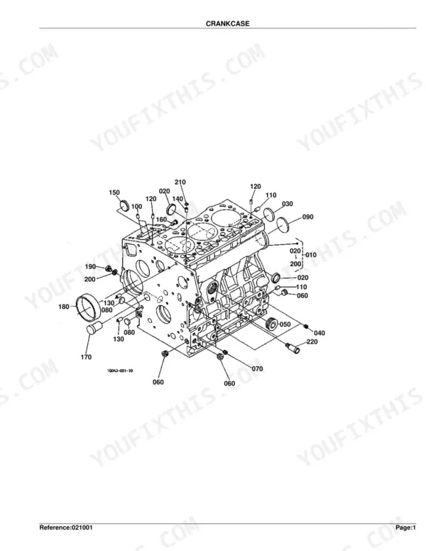
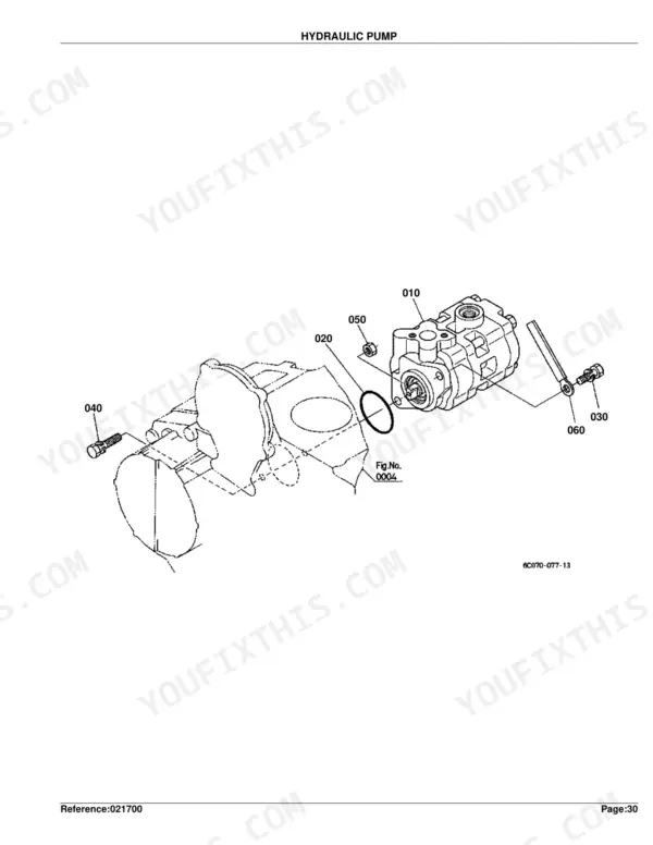
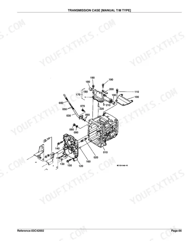
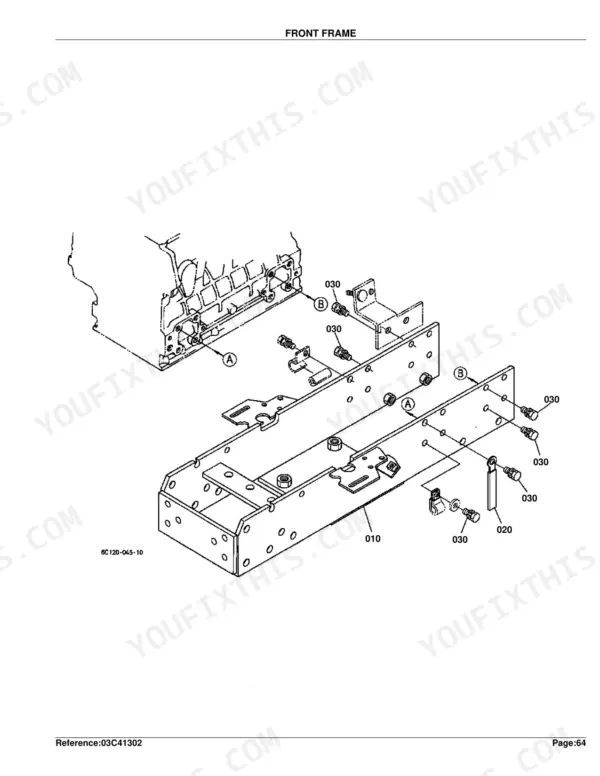
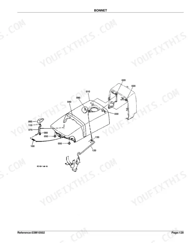
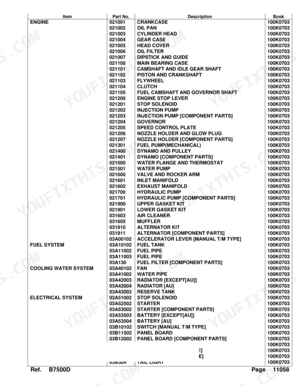
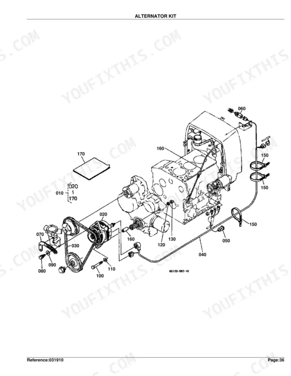
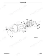
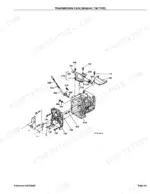
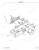
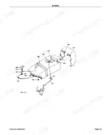
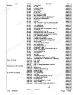
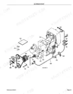
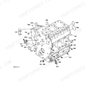
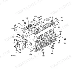
Part of the Kubota Parts Manuals.
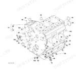
Open the Kubota B7500D Parts Catalog PDF (OEM #100K0703) to 336 pages of factory part numbers, exploded views, and component identification for the B7500D tractor. Engine coverage runs across crankcase, cylinder head, piston, crankshaft, injection pump, governor, and nozzle holders. The hydraulic section covers parts diagrams for the pump, control valve, cylinder, and all three oil line circuits (suction, delivery, and steering). The drivetrain section covers transmission case, rear differential, PTO shafts, and every gear shift fork tied to OEM part numbers and cross-references. Weights are listed too, so you order the right casting: 32 kgf (70.4 lb) for the crankcase assembly, 10.2 kgf (22.44 lb) for the cylinder head. Order the wrong number once and you'll see why factory data beats guesswork. Every assembly is bookmarked, so a tap lands you on the right exploded view.
What's Inside This Kubota B7500D Parts Manual
| System | Pages | Key Topics |
|---|---|---|
| Fuel System | Fuel Camshaft and Governor Shaft, Engine Stop Lever, Stop Solenoid, Injection Pump, Governor, Speed Control Plate, Nozzle Holder and Glow Plug, Nozzle Holder, Fuel Pump, Air Cleaner, Accelerator Lever, Fuel Tank, Fuel Pipe, Fuel Filter | |
| Cooling System | Water Flange and Thermostat, Water Pump, Fan, Water Pipe, Radiator, Reserve Tank | |
| Engine | Crankcase, Oil Pan, Cylinder Head, Gear Case, Oil Filter, Main Bearing Case, Camshaft and Idle Gear Shaft, Piston and Crankshaft, Flywheel, Valve and Rocker Arm, Inlet Manifold, Exhaust Manifold, Upper Gasket Kit, Lower Gasket Kit, Muffler, Differential Gear Case | |
| Electrical System | Dynamo and Pulley, Dynamo, Alternator Kit, Alternator, Starter, Battery, Switch, Panel Board, Head Light, Hazard Light, Tail Light, Electrical Wiring, Working Light Kit | |
| Clutch & Transmission | Clutch, Clutch Rod, Clutch Pedal, Clutch Housing, Transmission Case, Clutch Shaft, Main Gear Shift Fork, Range Gear Shift Fork, PTO Gear Shift Fork, Differential Lock Shift Fork, Main Gear Shift Lever, Range Gear Shift Lever, PTO Gear Shift Lever | |
| PTO | PTO Shaft, Mid PTO, PTO Protector | |
| Rear Axle, Differential & Brakes | Rear Axle Case, Rear Differential, Rear Axle, Brake, Brake Rod 1, Parking Brake Lever, Brake Pedal, Differential Lock Pedal, Rear Wheel | |
| Front Axle & Steering | Propeller Shaft, Front Wheel Propeller Shaft, Front Wheel Drive Lever, Front Axle Case, Front Differential, Differential Gear Shaft, Front Axle, Tie Rod, Steering Handle, Front Wheel | |
| Hydraulics & 3-Point Hitch | Hydraulic Pump, Hydraulic Control Lever, Hydraulic Oil Line, Hydraulic Cylinder, Feed Back Lever, Control Valve, 3-Point Linkage 2, 3-Point Linkage 1, Drawbar | |
| Body & Operator Station | Head Cover, Front Frame, Center Frame, Front Grille, Bonnet, Panel Cover, Side Cover, Shutter Plate, Fender, Fender Stay, Floor Seat, Seat Support, Step, ROPS, ROPS Kit | |
| Decals & Accessories | Label, Accessories and Service Parts | |
| Other Components | Dipstick and Guide, Front Shaft, 2nd Shaft, 3rd Shaft, 4th Shaft, Front Drive Shaft, Knuckle Arm, Drag Link, Universal Joint, Lower Link, Check Chain, Hitch, Lever Guide, Smv Emblem |
Kubota B7500D Common Problems This Manual Covers
Kubota B7500D tractor no-crank after storage, need starter or battery part number
Check the Starter exploded view on page 111, then turn to Starter [Component Parts] on page 113 to identify the solenoid, drive assembly, and brushes as separate line items. For battery replacement on non-AU models, use the parts list on page 115; the battery bracket assembly weighs 2.6 kgf (5.72 lb), so you can confirm the right group before ordering.
Manual Section: Starter [Component Parts] p. 113Hydraulic pump seals and internals needed, part numbers unclear from component diagram
Locate the Hydraulic Pump [Component Parts] exploded view on page 70. Internal seals, gears, and body parts run individually across pages 70-72. The pump assembly for serial numbers >=2L0006 weighs 2.22 kgf (4.884 lb) per page 69, so confirm your serial range matches before ordering internals; earlier configurations can differ.
Manual Section: Hydraulic Pump [Component Parts] p. 70Oil leaking from cylinder head area, unclear whether upper or lower gasket kit applies
Compare the Upper Gasket Kit on page 73, which covers head, valve cover, and intake gaskets, against the Lower Gasket Kit on page 75 for pan-side and crankcase seals. The cylinder head assembly weighs 10.2 kgf (22.44 lb) per page 11; pulling the head for a full reseal means the upper kit covers every sealing surface in one order.
Manual Section: Upper Gasket Kit p. 73Brake friction and rod part numbers unclear in Manual T/M brake assembly diagram
Pull up the Brake [Manual T/M Type] diagram on page 183 and note position numbers for each friction piece and hardware item. Cross-reference Brake Rod 1 on page 185 for rod and clevis components. These pages cover Manual T/M Type only, so verify your transmission configuration first. The clutch disk is listed at 0.88 kgf (1.936 lb) on page 30 if you need clutch parts too.
Manual Section: Brake [Manual T/M Type] p. 183Oil pan gasket and drain plug O-ring part numbers unclear, unsure if sold separately or as kit
Open the Oil Pan diagram on pages 8-9 and note position numbers for the gasket, drain plug, and O-ring separately; they are not bundled as a kit. Cross-check Oil Filter on page 17 while you order, since the filter assembly weighs 0.35 kgf (0.77 lb) and is replaced at the same interval. Lower Gasket Kit on page 75 covers more crankcase sealing components if you need broader coverage.
Manual Section: Oil Pan p. 8Frequently Asked Questions
How quickly can I access this manual after buying?
Instant download. The full 336-page searchable Parts Catalog is yours the moment payment clears. Open it on a laptop, tablet, or phone right at the workbench.
Am I able to print pages from this manual?
Yes. Print a chapter or just the pages for the job at hand, for use in your own shop. Any home or office printer works.
Are there hydraulic schematics in this Kubota B7500D manual?
This is a parts catalog, so it shows exploded parts diagrams rather than circuit schematics. It includes detailed exploded views of the hydraulic components, pump, control valve, cylinder, and oil lines, with OEM part numbers, not wiring-style circuit diagrams.
Which gasket kits are covered in this Kubota B7500D parts catalog?
Two complete gasket kits are listed. The Upper Gasket Kit on page 73 covers the head, valve cover, and intake gaskets. The Lower Gasket Kit on page 75 covers pan-side and crankcase seals. Together they provide full coverage for an engine reseal.
Does the B7500D parts catalog cover front axle and steering components?
Yes. The catalog includes exploded views and OEM part numbers for the front axle case, front differential, differential gear shaft, front axle, knuckle arm, drag link, tie rod, steering handle, and front wheel assemblies.




Reviews
There are no reviews yet.