
Part of the Kubota Parts Manuals.
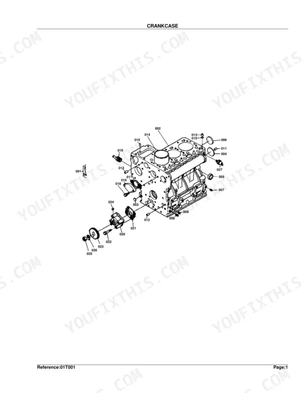
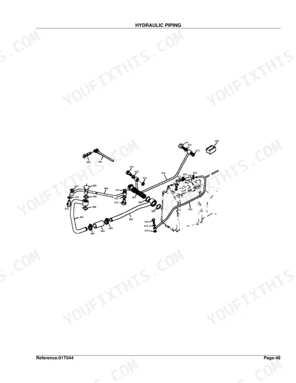
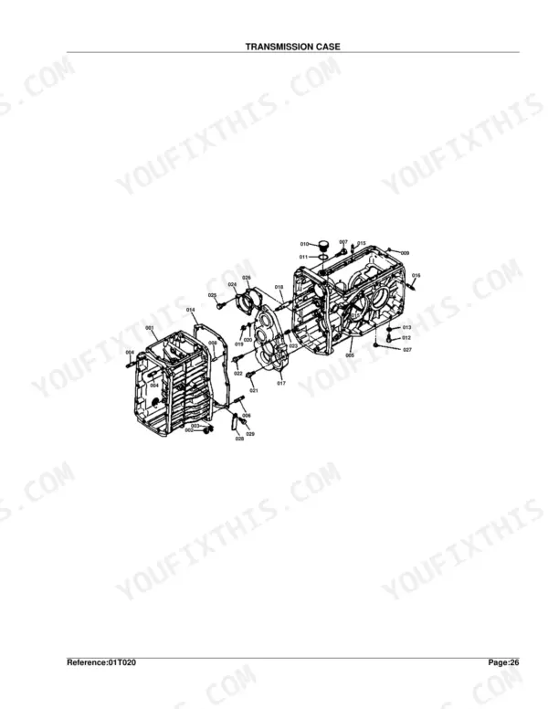
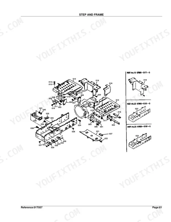
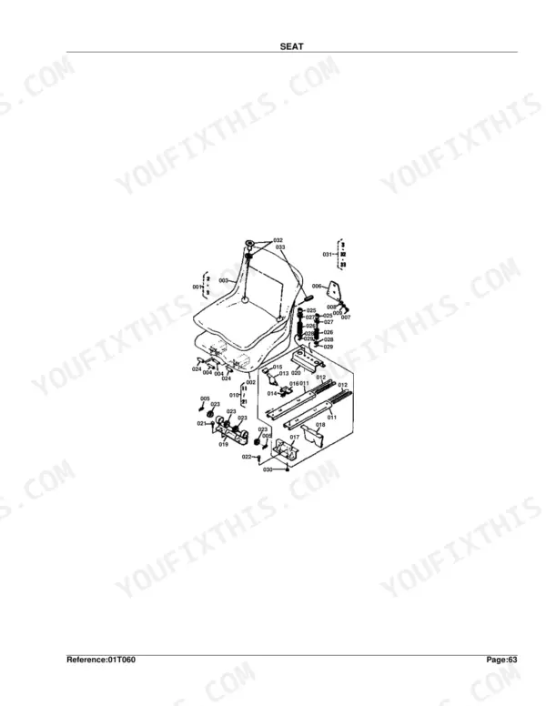
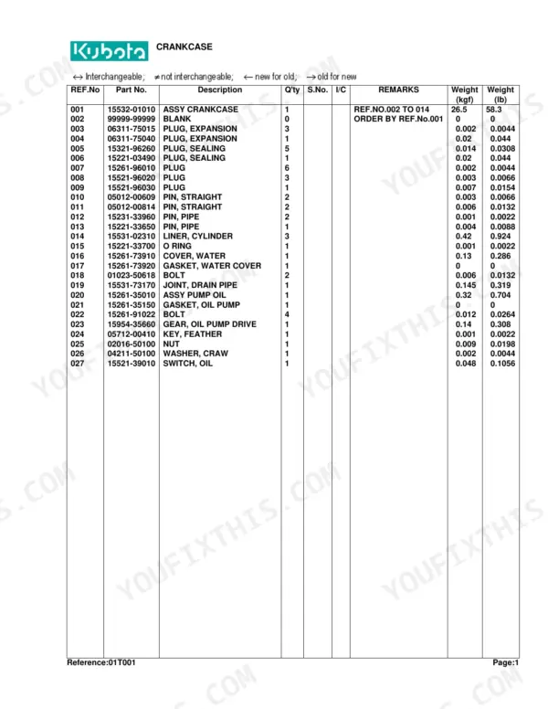
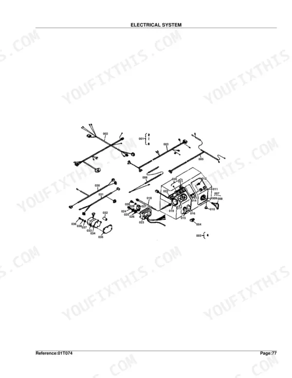
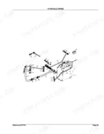
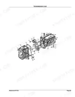
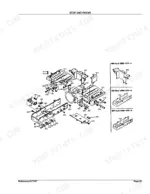
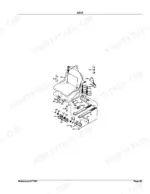
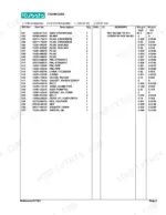
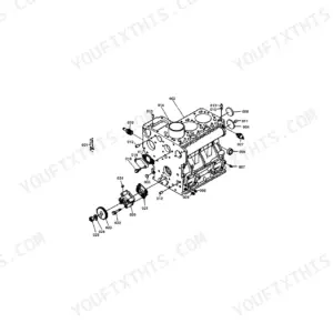
This is the factory parts catalog for the Kubota B8200DP tractor, a 202 page PDF that covers the machine built from 1983 to 1990. Each assembly appears as a numbered exploded view next to a parts list table, so you can pinpoint the exact component and order the right replacement part.
Coverage spans the whole tractor: engine, fuel and injection, cooling, the electrical system with dynamo and starter, transmission and clutch, rear axle and differential, brakes, steering, and the full hydraulic system including the control valve, piping and block.
Use it to find part numbers before you start a repair, understand how the hydraulic and electrical assemblies fit together, and avoid ordering the wrong piece. It is a reference for owners and mechanics maintaining a B8200DP, not a service how to.
What's Inside This Kubota B8200DP Parts Manual
| System | Pages | Key Topics |
|---|---|---|
| Clutch & Transmission | Transmission Case, Clutch, Th Shaft and Reverse Shaft, Main Speed Change, Speed Change Fork, Rotary Speed Change Fork, Speed Change Lever 1, Speed Change Lever 2, Clutch Pedal and Brake Pedal, Clutch Housing | |
| Fuel System | Engine Stop Lever, Nozzle Holder, Speed Control Plate, Governor, Fuel Camshaft, Injection Pump, Fuel Tank, Fuel Pipe, Decompress Wire and Engine Stop Wire, Air Cleaner, Fuel Filter | |
| Cooling System | Water Flange, Water Pump, Radiator | |
| Engine | Crankcase, Oil Pan, Cylinder Head, Gear Case, Main Bearing Case, Cylinder Head Cover, Inlet Manifold, Valve/Rocker Arm, Camshaft, Piston/Crankshaft, Flywheel, Muffler and Muffler Pipet, Bevel Gear Case | |
| Electrical System | Dynamo, Starter, Battery, Head Lamp and Flasher Lamp, Dynamo and Starter | |
| PTO | 7Th Shaft and PTO Shaft | |
| Rear Axle, Differential & Brakes | Axle Case, Rear Differential, Rear Axle and Rear Wheel, Rear Wheel, Brake, Brake Rod, Front Axle Case | |
| Front Axle & Steering | Front Drive Shaft and 6 Th Shaft, Front Drive Fork, Steering, Front Axle Arm, Knuckle Arm, Front Differential, Front Wheel | |
| Hydraulics & 3-Point Hitch | Gear Pump, Hitch, Case Cover and Lift Arm, Control Valve, Hydraulic Piping, Hydraulic Block, Lift Rod | |
| Body & Operator Station | Step and Frame, Fender, Seat, Hood and Panel, Hood Bracket, Check Chain and Bracket, Front Weight Bracket | |
| Decals & Accessories | Name Plate, Accessories and Service Parts | |
| Other Components | St Shaft and 2 Nd Shaft, Rd Shaft, Release Lever, Dustproof Net, Skirt, Bevel Gear, Drive Shaft |
Quick Reference Specifications
| Specification | Value | Page |
|---|---|---|
| Weight | 0.35 kgf | p. 100 |
| Oil PAN weight | 1.1 kgf | p. 8 |
Kubota B8200DP Common Problems This Manual Covers
No-start electrical faults
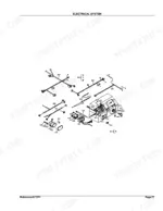
B8200DP no-start problems usually trace to fuses, relays, the fuel shutoff solenoid, wiring or the key switch. The Electrical System section shows these components with part numbers to order replacements.
Manual Section: Electrical System p. 157Hydraulic or loader cylinder leaks
Worn cylinder seals, often on a front loader circuit, are a common source of weak or leaking hydraulics. The Control Valve section breaks the valve down into its parts for a correct rebuild.
Manual Section: Control Valve p. 95Steering or hitch weak with loader on
When the power steering or 3-point hitch only works with the loader disconnected, the fault is often in the hydraulic block or routing. This section shows the block components and their part numbers.
Manual Section: Hydraulic Block p. 103Front hub or knuckle wear
Teardown of the front axle can reveal worn seals or damage in the knuckle area. The Knuckle Arm section provides the exploded view and part numbers for that assembly.
Manual Section: Knuckle Arm p. 178Weak charging system
A battery that will not stay charged often means a failing dynamo or starter circuit. The Dynamo and Starter section lists these units and their part numbers.
Manual Section: Dynamo and Starter p. 170Coolant leaks or overheating
Overheating and coolant loss can trace to the radiator or its hoses. The Radiator section shows the radiator assembly and related parts to order.
Manual Section: Radiator p. 168Frequently Asked Questions
Which tractor does this parts catalog cover?
It covers the Kubota B8200DP tractor, built from 1983 to 1990, across the full machine from engine to hydraulics.
Does it include part numbers and exploded diagrams?
Yes. Each section pairs a numbered exploded view with a parts list table, so you can identify a component and order the correct Kubota part number.
Where do I find electrical parts for a no-start?
The Electrical System section covers the wiring, switches and related components behind most no-start faults, so you can source the right parts. p. 157
Does it cover the hydraulic control valve?
Yes. The Control Valve section breaks the valve into its parts, and the Hydraulic Piping and Block sections cover the surrounding circuit. p. 95
What format is this manual in?
Immediate download of the complete 202-page searchable Parts Catalog. Open it on any device, from the laptop at your desk to the phone in the field.
Can I print specific sections of this Kubota B8200DP Parts Catalog?
Yes. Many buyers print one chapter at a time for their own shop and keep the rest on a tablet.
Are hydraulic system diagrams in this Kubota B8200DP Parts Catalog?
This is a parts catalog with exploded-view diagrams and OEM part numbers. It covers hydraulic components, pump, control valve, cylinder, and oil lines with numbered part lists — not electrical circuit drawings.


Reviews
There are no reviews yet.