
Part of the Kubota Parts Manuals.
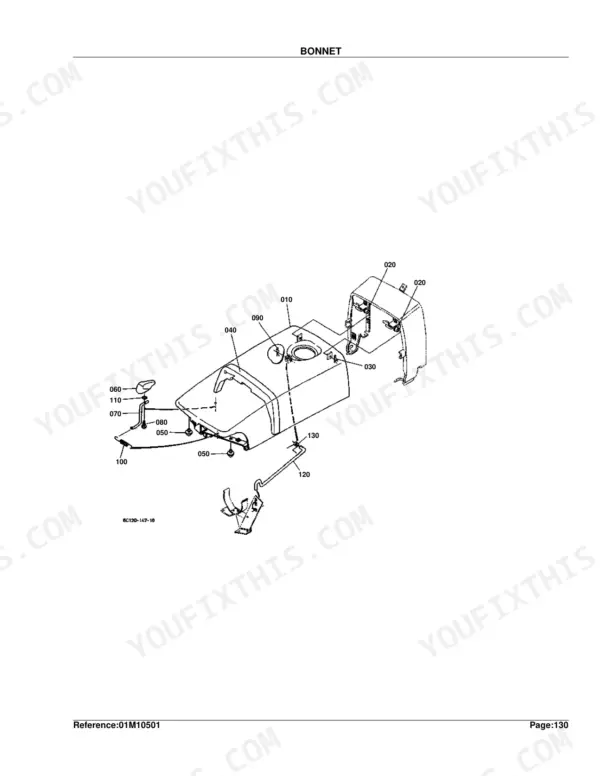
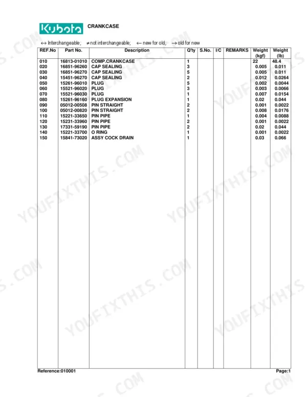
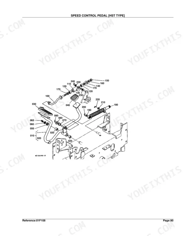
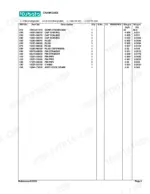
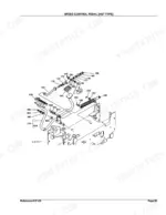
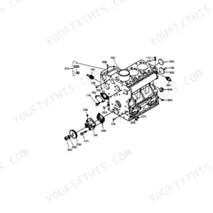
This Kubota Parts Catalog covers the B7400HSD compact tractor and lists the factory part numbers for the entire machine across 323 pages. Every assembly is shown as an exploded diagram paired with a parts list giving the reference number, Kubota part number, quantity, and the serial number range each part fits.
Use it to identify and order the exact replacement parts for the engine, fuel and cooling systems, clutch, transmission and rear axle, hydrostatic transmission, hydraulics, steering, and electrical components. Because parts often change across serial number ranges, the catalog's serial number and interchangeability columns let you confirm a part fits your tractor before you buy. It is the reference for anyone rebuilding or maintaining a B7400HSD who needs the correct part numbers the first time.
What's Inside This Kubota B7400HSD Parts Manual
| System | Pages | Key Topics |
|---|---|---|
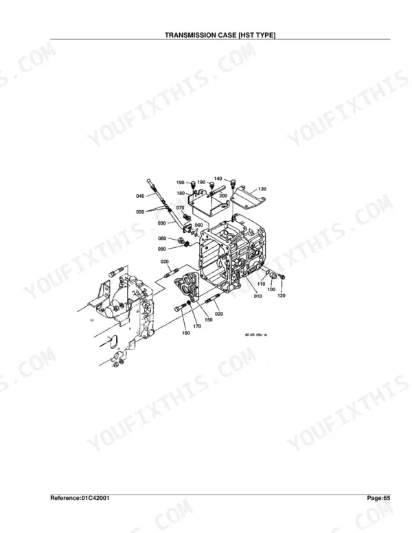
| Clutch & Transmission | Clutch, Clutch Rod, Clutch Pedal, Clutch Housing, Clutch Dipstick and Guide, Transmission Case, Clutch Shaft, HST, 2Nd Shaft, 3Rd Shaft, 4Th Shaft, Range Gear Shift Fork, PTO Gear Shift Fork, Differential Lock Shift Fork, Neutral Holder Link, Range Gear Shift Lever | |
| Fuel System | Fuel Camshaft and Governor Shaft, Engine Stop Lever, Injection Pump, Governor, Speed Control Plate, Nozzle Holder and Glow Plug, Nozzle Holder, Fuel Pump, Air Cleaner, Accelerator Lever, Fuel Tank, Fuel Pipe, Fuel Filter, Stop Solenoid, Speed Control Pedal | |
| Cooling System | Water Flange and Thermostat, Water Pump, Fan, Water Pipe, Radiator, Reserve Tank | |
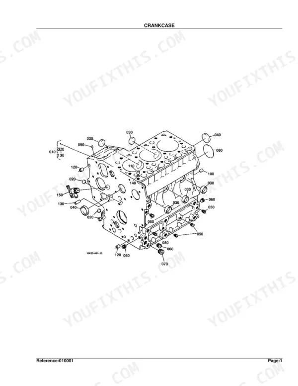
| Engine | Crankcase, Oil Pan, Cylinder Head, Gear Case, Head Cover, Oil Filter, Dipstick and Guide, Oil Pump, Main Bearing Case, Camshaft and Idle Gear Shaft, Piston and Crankshaft, Flywheel, Valve and Rocker Arm, Inlet Manifold, Exhaust Manifold, Upper Gasket Kit | |
| Electrical System | Dynamo and Pulley, Dynamo, Starter, Battery, Switch, Panel Board, Head Light, Hazard Light, Tail Light, Electrical Wiring, Warking Light Kit | |
| Undercarriage & Travel | Steering Controller | |
| PTO | PTO Shaft, Mid PTO, PTO Protector | |
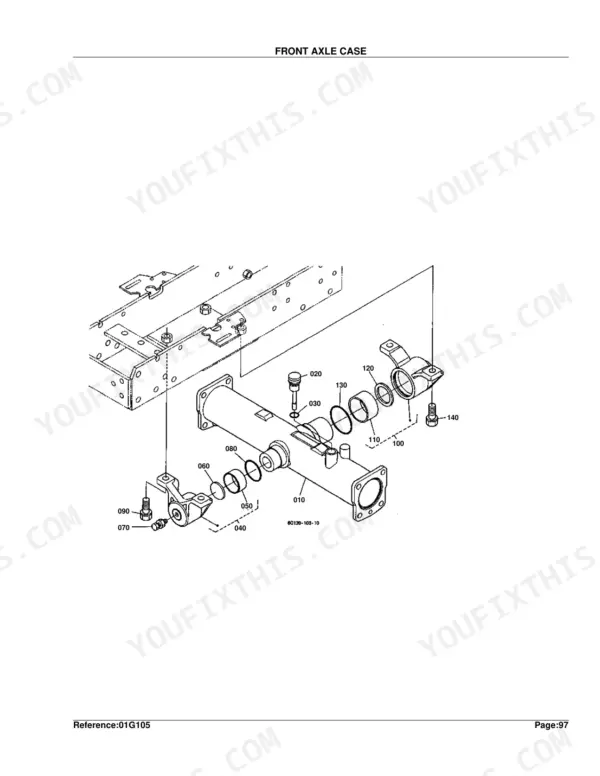
| Rear Axle, Differential & Brakes | Rear Axle Case, Rear Differential, Rear Axle, Brake, Brake Rod 1, Parking Brake Lever, Brake Pedal, Differential Lock Pedal, Front Axle Case, Differential Gear Shaft, Rear Wheel | |
| Front Axle & Steering | Propeller Shaft, Front Wheel Propeller Shaft, Front Wheel Drive Lever, Front Differential, Front Axle, Front Drive Shaft, Knuckle Arm, Drag Link, Tie Rod, Steering Handle, Front Wheel | |
| Hydraulics & 3-Point Hitch | Hydraulic Pump, Hydraulic Control Lever, Hydraulic Oil Line, Hydraulic Cylinder, Feed Back Lever, Control Valve, 3-Point Linkage 2, Lower Link, 3-Point Linkage 1, Drawbar, Hitch | |
| Body & Operator Station | Front Frame, Center Frame, Front Grille, Bonnet, Panel Cover, Side Cover, Shutter Plate, Fender, Fender Stay, Floor Seat, Seat Support, Step, ROPS, Smv Emblem, ROPS Kit | |
| Decals & Accessories | Label, Accessories and Service Parts | |
| Other Components | Front Shaft, Speed Set Lever, Check Chain, Lever Guide |
Every system also includes a figure, a parts list, and interchangeability symbols legend.
Quick Reference Specifications
| Specification | Value | Page |
|---|---|---|
| Hydraulic oil filter weight | 0.39 kgf | p. 229 |
| Engine oil filter weight | 0.195 kgf | p. 17 |
| Clearance (Shim Injection Pump 16006-52092) | 0.20mm | p. 37 |
| Clearance (Shim Injection Pump 16006-52112) | 0.25mm | p. 37 |
Kubota B7400HSD Common Problems This Manual Covers
Hydrostatic drive performance loss
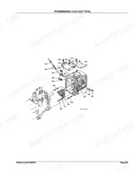
Weak forward or reverse movement and slow response are recurring HST complaints, especially when service intervals are missed. The HST section gives the exploded view and part numbers for the hydrostatic unit.
Manual Section: HST [Hst Type] p. 145Weak or slow three-point hitch and hydraulics
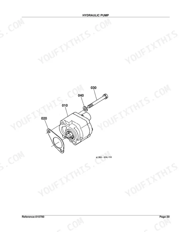
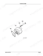
Hydraulic functions that lift slowly or drop off often trace to worn pump components or internal leakage. The hydraulic pump section identifies the pump and its component parts for replacement.
Manual Section: Hydraulic Pump p. 64Hard starting or no crank
A tractor that cranks slowly or not at all usually needs starter or battery work. The starter section lists the assembly and its component parts so you can order the right pieces.
Manual Section: Starter p. 101Overheating from a failing radiator
Overheating can follow a damaged or clogged radiator and worn cooling hoses. The radiator section gives the exploded diagram and part numbers for the cooling package.
Manual Section: Radiator [Except[Au]] p. 91Clutch wear on gear-drive work
Clutch wear shows up as slipping or difficulty transferring power. The clutch section identifies the disc, cover, and related hardware for a clutch job.
Manual Section: Clutch p. 30Routine filter replacement
Owners most often shop for filters and routine service parts rather than major internals. The oil filter section shows the engine oil filter and its part number for scheduled changes.
Manual Section: Oil Filter p. 16Frequently Asked Questions
Which tractor does this parts catalog cover?
It covers the Kubota B7400HSD compact tractor. The catalog documents factory part numbers for the whole machine, from the engine and cooling system through the transmission, hydraulics, and electrical components.
How are the parts organized and does it show serial number ranges?
Each assembly is an exploded diagram with a parts list giving the reference number, Kubota part number, quantity, and the serial number range. The instructions page explains the columns and interchangeability symbols so you can confirm a fit. p. 1
Does it list hydrostatic transmission parts?
Yes. The HST section shows the hydrostatic transmission assembly, and a following component-parts section breaks it down further, giving part numbers for a repair or rebuild. p. 145
Does it include engine and cooling parts?
Yes. The catalog covers engine assemblies from the crankcase onward and the full cooling package, including the radiator section with its part numbers for the radiator and related hardware. p. 91
How will I receive this Kubota B7400HSD Parts Catalog?
A 323-page Parts Catalog in searchable PDF format, available the moment you complete checkout. Open it on a computer, tablet, or phone. No shipping wait.
Am I able to print pages from this manual?
Yes. Print individual pages or full chapters for your own shop use, on letter or A4 paper.


Reviews
There are no reviews yet.