

Part of the Kubota Parts Manuals.
This is the Kubota LA302 loader parts catalog, a 42 page illustrated PDF that lays out the loader in its exact factory assemblies. It covers the main frame, brace, boom, the control valve in both 3 position and 4 position types, the control lever, the boom and bucket cylinders, and the full hydraulic hose, tube, and block circuits.
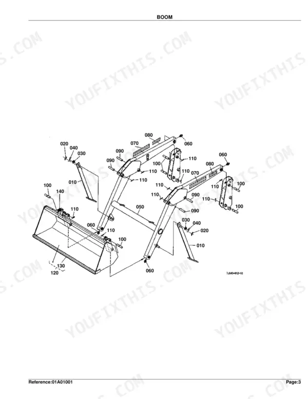
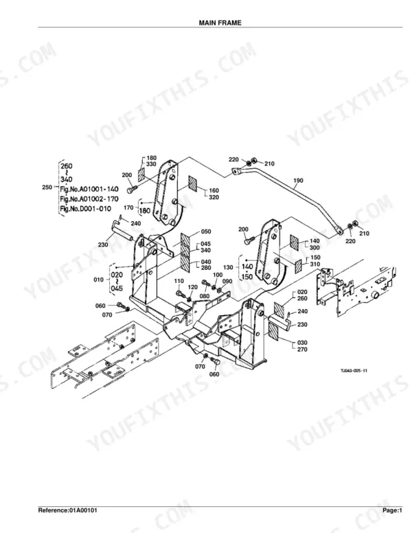
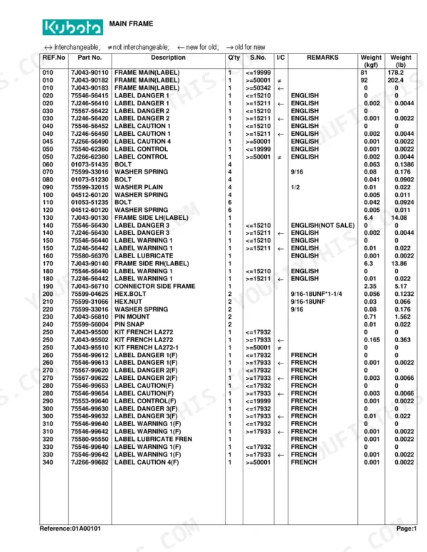
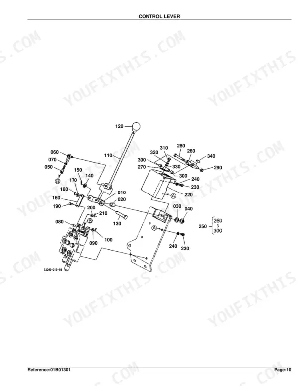
Each section pairs an exploded diagram with a numbered parts list carrying Kubota part numbers, quantities, serial number ranges, and component weights. You can match a reference number on the drawing to the right part, and the serial columns tell you which version fits your loader.
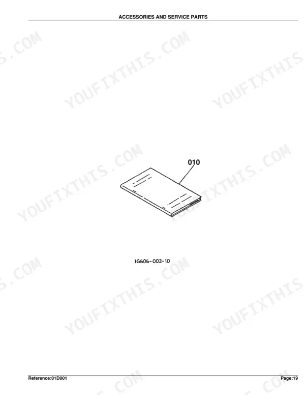
Use it to identify control valve and detent parts, hydraulic hoses and couplers, cylinder seal kits, and frame hardware for repairs like a loader that will not lower, a leaking coupler, or a boom rebuild. Operator manual accessories are listed at the back.
Complete the set for your LA302
- Operator Manual: Kubota LA272–LA402 Series Front Loader Operator Manual
- Repair Manual: Kubota LA271–LA402 Series Front Loader Workshop Manual
What's Inside This Kubota LA302 Parts Manual
| System | Pages | Key Topics |
|---|---|---|
| Main Frame | 4-6 | Main Frame Components Diagram, Old Part Diagram, Main Frame Parts List |
| Brace | 7-8 | Assembly Parts, Fasteners for Brace, Comp Guard Front Parts |
| Boom | 9-10 | Assembly Parts, Fasteners and Pins, Labels and Bucket Components |
| Control Valve | 11-16 | Control Valve Diagram (3 Position Valve Type), Control Valve Diagram (4 Position Valve Type) |
| Control Valve [Component Parts] | 17-22 | Component Parts List (3 Position Valve Type), Component Parts List (4 Position Valve Type) |
| Control Lever | 23-26 | Control Lever Diagram (S.No. <=19999), Control Lever Parts List (S.No. <=19999), Control Lever Diagram (S.No. >=50001), Control Lever Parts List (S.No. >=50001) |
| Cylinder/Hydraulic Hose | 27-28 | Cylinder Components, Hydraulic Hoses, Band Code |
| Hydraulic Hose(Hyd.Outlet Block) | 29-30 | Hydraulic Hoses, Coupler and Plugs, Sleeve and Band Code |
| Hydraulic Tube | 31-32 | Hydraulic Tubes, Clamp and Fasteners |
| Cylinder (Boom)[Component Parts] | 33-34 | Boom Cylinder Tube Components, Rod, Head, Piston, And Nut Components, Seal, Fittings, And Plugs |
| Cylinder (Bucket)[Component Parts] | 35-36 | Bucket Cylinder Tube Components, Rod, Head, Piston, And Nut Components, Seal, Fittings, And Plugs |
| Hydraulic Block | 37-41 | Hydraulic Block Diagram (S.No. <=19999), Hydraulic Block Parts List (S.No. <=19999), Hydraulic Block Diagram (S.No. >=50001), Hydraulic Block Parts List (S.No. >=50001), Accessories and Service Parts Diagram |
| Accessories and Service Parts | 42 | Operator's Manual English, Operator's Manual French |
Quick Reference Specifications
| Specification | Value | Page |
|---|---|---|
| Main Frame (Part No. 7J043-90110) Weight | 81 kgf | p. 6 |
| Main Frame (Part No. 7J043-90182) Weight | 92 kgf | p. 6 |
| Hex.Bolt (Part No. 75599-04625) Size | 9/16-18UNF*1-1/4 | p. 6 |
| Hex.Nut (Part No. 75599-31066) Size | 9/16-18UNF | p. 6 |
| Brace (Part No. 75536-57400) Weight | 21 kgf | p. 8 |
| Hex.Bolt (Part No. 75599-04630) Size | 9/16-18UNF*1-1/2 | p. 8 |
| Hex.Bolt (Part No. 75599-04530) Size | 1/2-20UNF*1-1/2 | p. 8 |
| Boom (Part No. 7J043-58010) Weight | 96 kgf | p. 10 |
| Fitting Grease (Part No. 75599-81520) Thread | 1/4-28T.T. | p. 10 |
| Stay Valve (Part No. 75536-66110) Weight | 2.4 kgf | p. 12 |
| Cylinder 1 (Part No. 75536-63010) Weight | 6.3 kgf | p. 28 |