


Part of the Kubota Parts Manuals.
This is the Kubota B6100HST-E parts catalog, a 130-page exploded-view guide for the hydrostatic four-wheel-drive compact tractor. Every section pairs a numbered parts diagram with the corresponding Kubota part numbers, quantities, and serial-number applicability. It covers the whole tractor: the diesel engine, clutch, transmission and PTO shafts, differential, front axle and front wheel hub components, hydrostatic transmission, control valve and hydraulics, steering, brakes, radiator, fuel system, three-point linkage, and electrical parts. Use it to pin down the exact replacement part before you buy, check part quantities per assembly, and understand how each group goes back together during a rebuild. Delivered as a downloadable PDF that you can search, zoom, and print for the workshop.
What's Inside This Kubota B6100HST-E Parts Manual
| System | Pages | Key Topics |
|---|---|---|
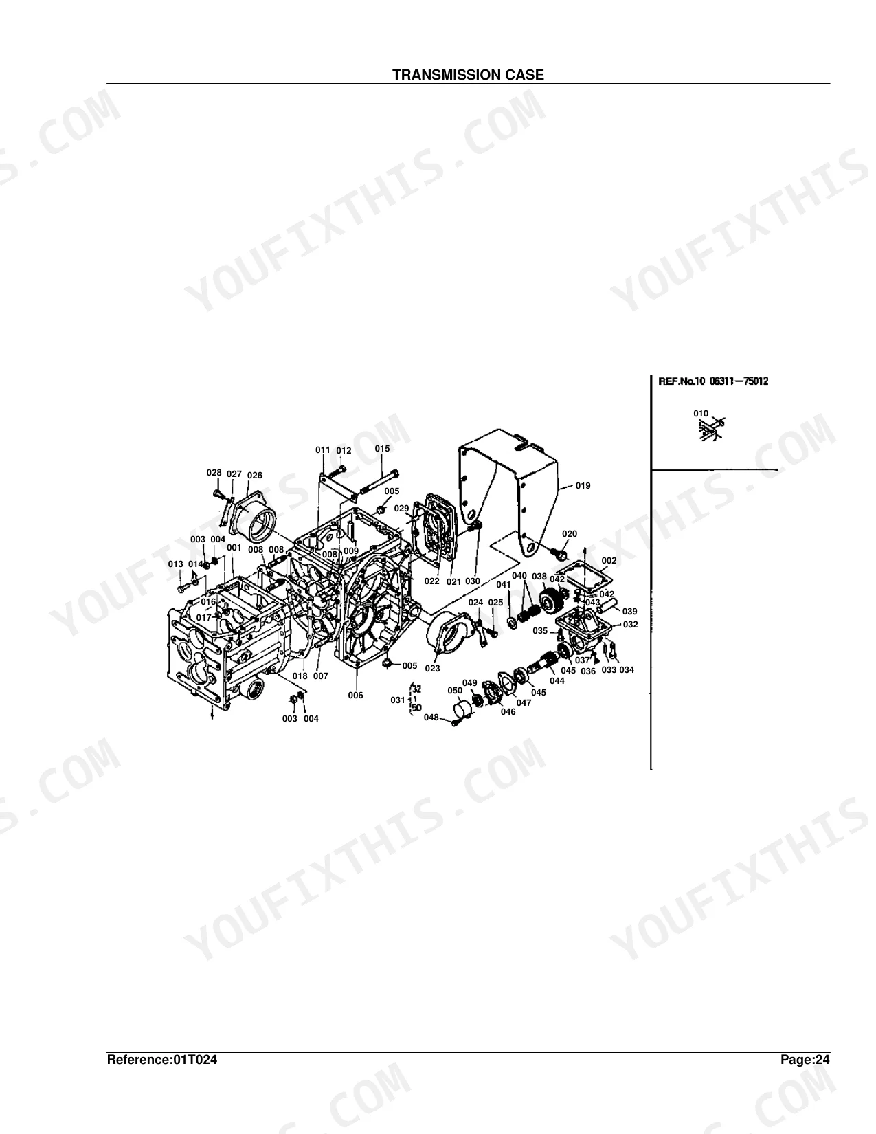
| Clutch & Transmission | Clutch, Transmission Case, Clutch Rod, 1st Shaft 4th Shaft, 2nd Shaft Front Wheel Shaft, Aux. Speed Change, Rotary Speed Change, Hydrostatic Transmission, Speed Change 1, Speed Change 2, Clutch Housing | |
| Fuel System | Nozzle Holder, Injection Pump, Speed Control Plate, Governor, Fuel Tank, Air Cleaner, Fuel Filter | |
| Cooling System | Radiator | |
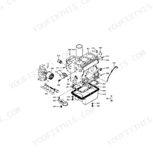
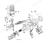
| Engine | Crankcase, Cylinder Head, Gear Case, Bearing Case, Breather, Inlet Manifold, Valve Rocker Arm, Head Cover, Camshaft, Piston Crankshaft, Flywheel, Muffler | |
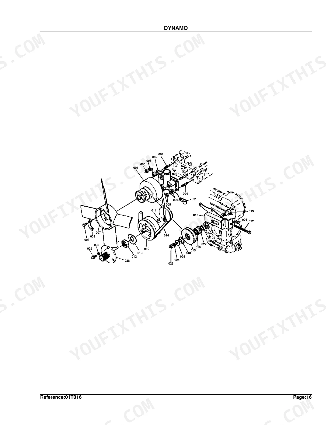
| Electrical System | Dynamo, Starter, Battery | |
| PTO | 3rd 5th PTO Shaft | |
| Rear Axle, Differential & Brakes | Axle Case, Brake, Brake Rod | |
| Front Axle & Steering | Steering, Front Wheel Support, Front Axle, Front Wheel Hub | |
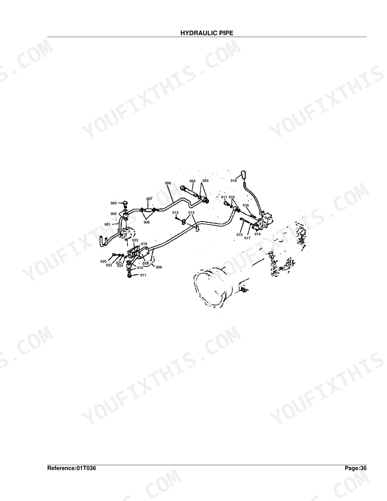
| Hydraulics & 3-Point Hitch | Oil Pressure Pump, Hydraulic Pipe, Control Valve, Hydraulics 1, Hydraulics 2, 3-Point Linkage | |
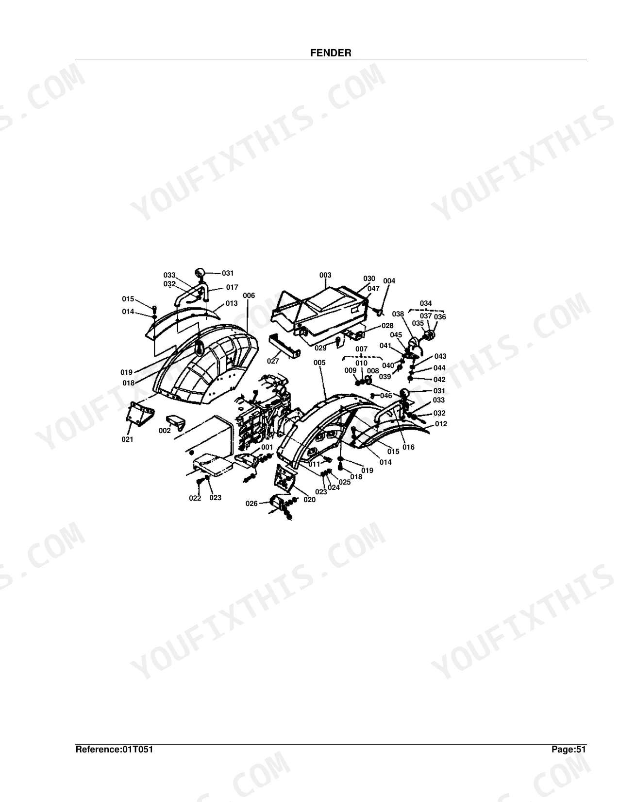
| Body & Operator Station | Case Cover, Seat, Fender, Bonnet, Panel | |
| Decals & Accessories | Name Plate, Accessory and Service Parts | |
| Other Components | Wheel Hub, Differential, Release Rod |
Quick Reference Specifications
| Specification | Value | Page |
|---|---|---|
| Dynamo Weight | 1.7 kgf | p. 36 |
| Battery Weight | 9.3 kgf | p. 114 |
| Bonnet Weight | 9.2 kgf | p. 108 |
Kubota B6100HST-E Common Problems This Manual Covers
Hydrostatic drive loss or weak movement
The B6100HST-E may not creep in forward or reverse, or lose drive, when the HST pump and motor wear, fluid is low, or the suction screen clogs. The hydrostatic transmission group shows its internal parts.
Manual Section: Hydrostatic Transmission p. 77Engine overheating or hard starting
A blocked radiator, low coolant, or debris-packed fins cause overheating and power loss. The radiator group lists the core, cap, and hoses to service.
Manual Section: Radiator p. 1033-point hitch slow or weak
The rear hitch can lift slowly or weakly when linkage or hydraulic engagement parts wear. The three-point linkage group breaks out the arms, pins, and related hardware.
Manual Section: 3-Point Linkage [Ep Dp] p. 125Steering becomes heavy
Heavy or unresponsive steering points to linkage wear or a hydraulic supply issue. The steering group identifies the box and linkage parts that owners rebuild.
Manual Section: Steering p. 85PTO slips or will not engage
PTO drivetrain wear or clutch trouble can stop the PTO from engaging or make it slip under load. The PTO shaft group shows the shafts and gears involved.
Manual Section: 3rd 5th PTO SHAFT p. 65Oil leaks around the engine
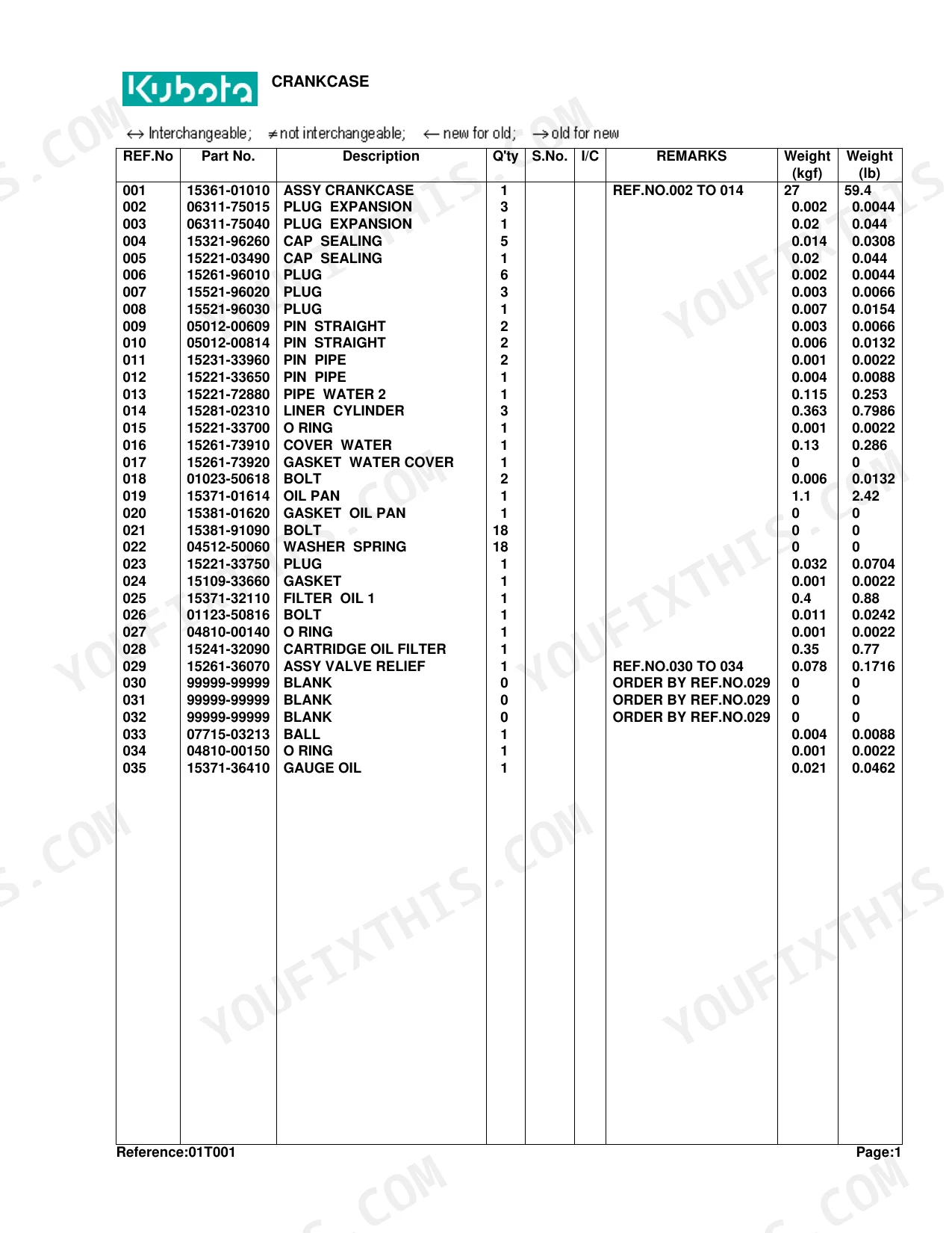
Aged seals and gaskets let oil seep from the engine and crankcase. The crankcase group breaks out the seals, plugs, and gaskets to renew during a repair.
Manual Section: Crankcase p. 5Frequently Asked Questions
Which tractor does this catalog cover?
It covers the Kubota B6100HST-E hydrostatic four-wheel-drive compact tractor, across 130 pages of exploded parts diagrams with Kubota part numbers.
Does it include hydrostatic transmission parts?
Yes. The hydrostatic transmission group gives the diagram and part numbers for the HST unit, useful when drive is weak or the tractor will not move. p. 77
Can I look up front axle parts?
Yes. The front axle group covers the EP front axle components and their part numbers, so you can identify worn 4WD drivetrain parts before ordering. p. 121
How do I get the file?
You download the PDF instantly after checkout and keep it on your device. There is no shipping, so you can begin identifying parts immediately.
Is this Kubota B6100HST-E Parts Catalog a digital download?
Yes. After payment you receive an instant PDF download of the full 130-page searchable Parts Catalog. Open it on a laptop, tablet, or phone right in the shop.
Is this Kubota B6100HST-E Parts Catalog printable?
Yes, print as many copies as you like with no restrictions. Many mechanics print just the section they need and bring it to the shop floor.
Are there hydraulic schematics in this Kubota B6100HST-E manual?
This is a parts catalog, so it shows exploded parts diagrams rather than circuit schematics. It includes detailed exploded views of the hydraulic components, pump, control valve, cylinder, and oil lines, with OEM part numbers, not wiring-style circuit diagrams.


Reviews
There are no reviews yet.