


This is the Kubota L275 parts catalog, the factory reference for identifying and ordering components on the L275 tractor, including the 4WD L275DT. Its 262 pages are organized by system, covering the engine, clutch and transmission, rear axle and differential, hydraulics and three-point hitch, front axles and steering for both 2WD and 4WD, and the full electrical wiring diagram.Each part is shown on an exploded diagram and listed with its reference number, Kubota part number, description, quantity, and serial-number range, so you can match parts to your exact machine and avoid ordering the wrong version.For owners tackling common L275 jobs like 4WD front-axle repairs, differential rebuilds, or wiring troubleshooting, this catalog identifies every piece involved. It is a searchable, printable PDF download you can keep on the bench or the phone in your pocket.
What's Inside This Kubota L275 Parts Manual
| System | Pages | Key Topics |
|---|---|---|
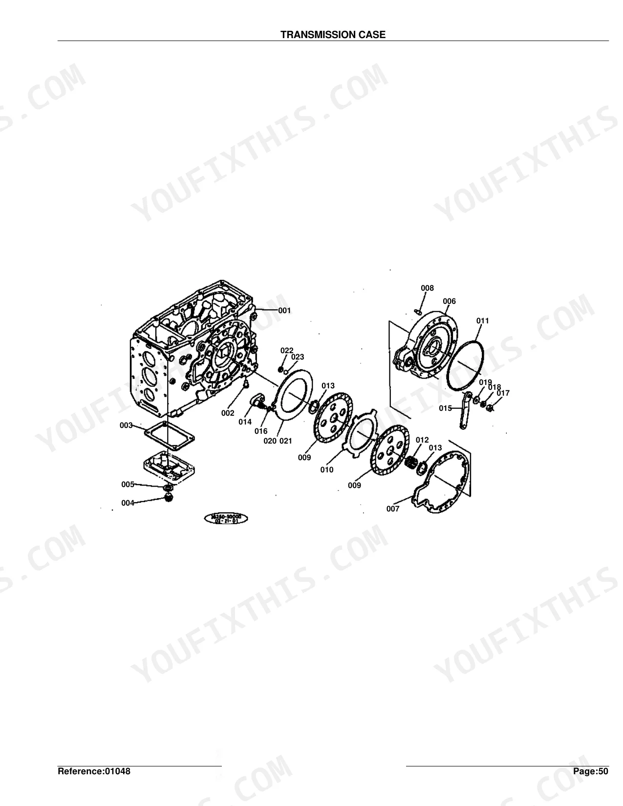
| Clutch & Transmission | Mid Case, Main Shift Lever, Reverse Shaft, Speed Change System 1, Speed Change System 2, PTO Shift Lever, Transmission Case, Clutch Housing | |
| Fuel System | Hand Accelerator, Fuel Tank, Fuel Filter, Air Cleaner | |
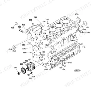
| Engine | Gear Case, Diff Bearing Case, Under Muffler, Bevel Gear Case | |
| Electrical System | Battery Support, Head Lamp, Wiring Diagram, Tail Lamp, Hazard Lamp | |
| PTO | Power Take-Off Shaft | |
| Rear Axle, Differential & Brakes | Spiral Bevel Pinion, Differential Lock Pedal, Rear Axle, Brake Pedal, Rear Wheel, Axle Case | |
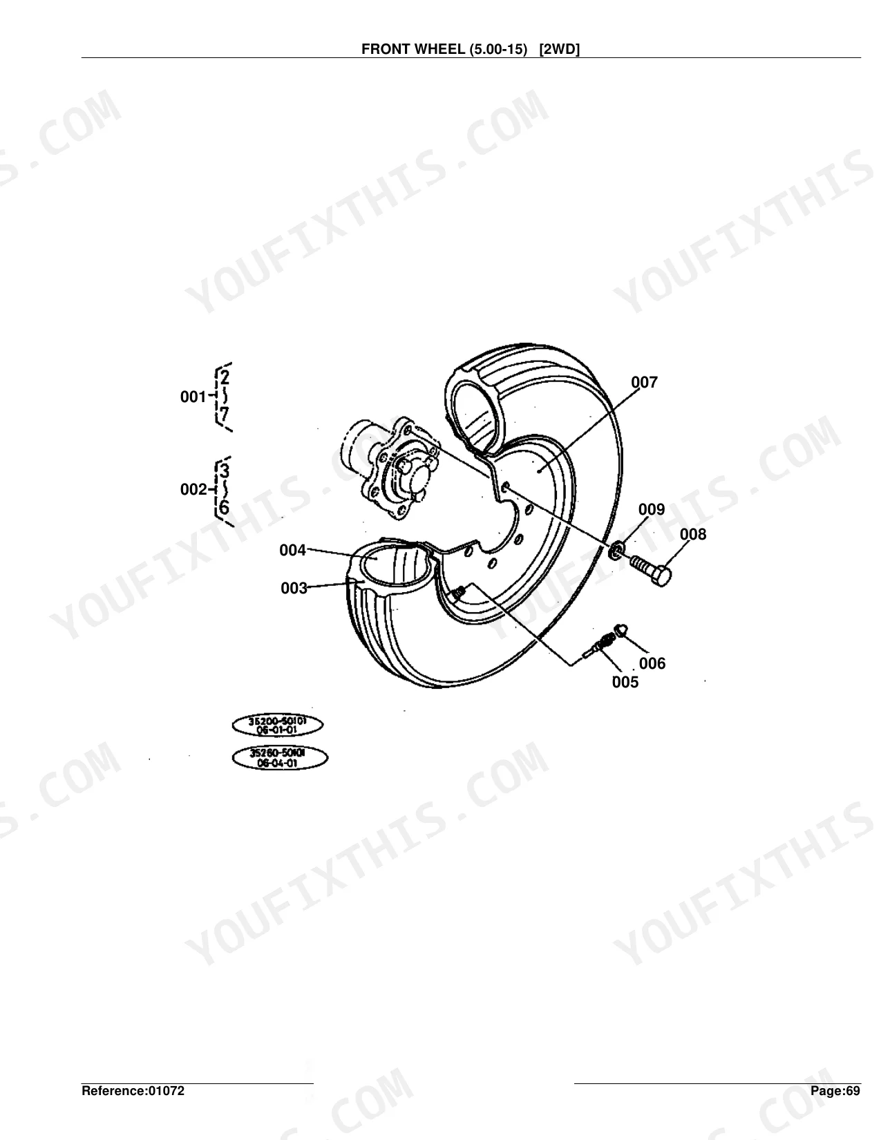
| Front Axle & Steering | Steering Wheel, Front Wheel, Front Wheel/L275, Front Wheel Hub, Steering Linkage, Front Axle, Front Axle Support, Propeller Shaft, Steering, Steering Section Parts, Power Steering, Drag Link, Knuckle Arm, Front Axle Bracket | |
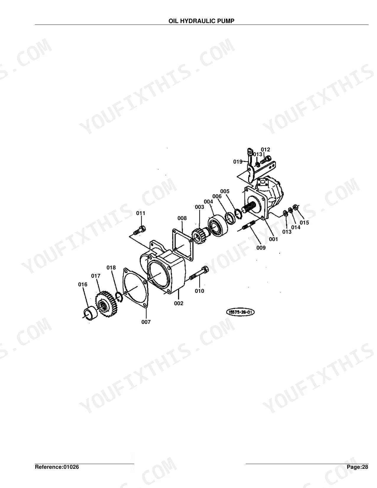
| Hydraulics & 3-Point Hitch | Oil Hydraulic System 1, Oil Hydraulic System 2, Oil Hydraulic Cylinder, Oil Hydraulic Cylinder Cover, Lift Arm, Oil Hydraulic Piping, 3-Point Link 1, 3-Point Link 2, Draft Control, Relief Valve, Flow Priority Valve, Swing Drawbar | |
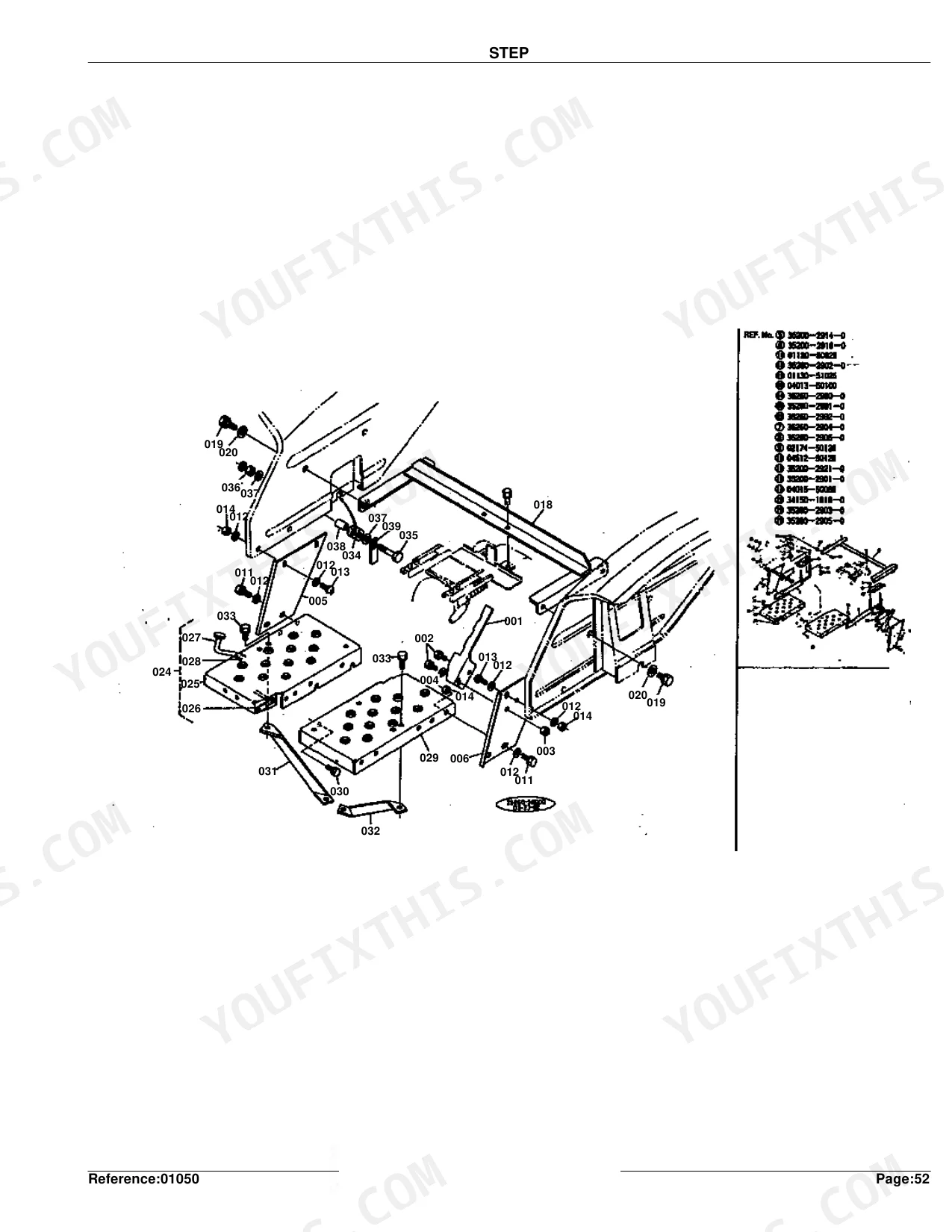
| Body & Operator Station | Safety Cover, Hood, Conduct Shaft, Step, Panel 1, Panel 2, Mission Cover, Seat, S.M.V.Emblem Bracket, Fender | |
| Decals & Accessories | Label | |
| Other Components | Bumper, Gear Drive System, Differential System, Differential Case, Drive Case |
Quick Reference Specifications
| Specification | Value | Page |
|---|---|---|
| Oil Pan Weight | 11.4 kgf (25.08 lb) | p. 9 |
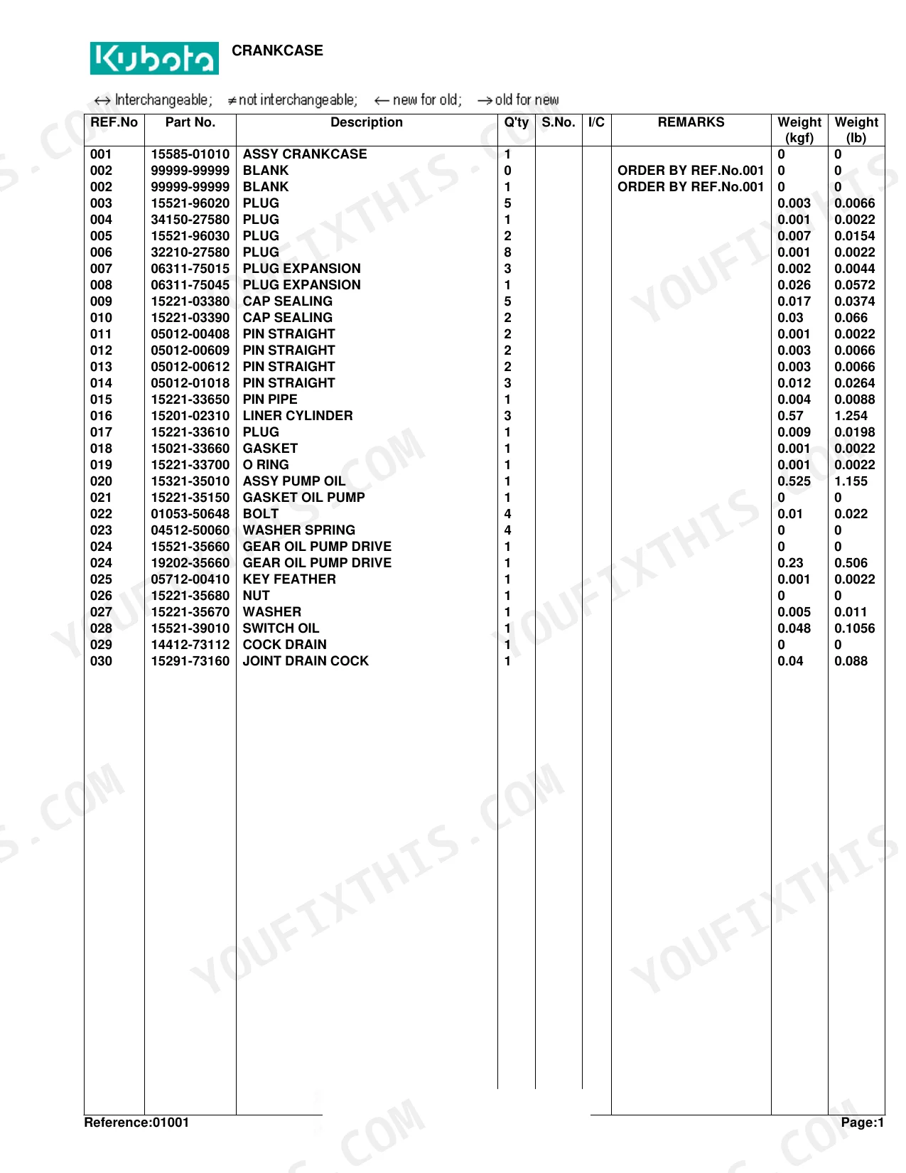
| Assy Crankshaft Weight (S.No. <=2259) | 13.42 kgf (29.524 lb) | p. 25 |
| Assy Housing Flywheel Weight (Dual Clutch) | 15.75 kgf (34.65 lb) | p. 29 |
| Assy Dynamo Weight | 3.25 kgf (7.15 lb) | p. 47 |
| Assy Radiator Weight | 6 kgf (13.2 lb) | p. 51 |
| Housing Clutch Weight (Dual Clutch) | 61 kgf (134.2 lb) | p. 216 |
| Assy Rear Wheel Weight (11.2-24) | 122 kgf (268.4 lb) | p. 154 |
| Case Transmission Weight | 33.2 kgf (73.04 lb) | p. 105 |
| Assy Tank Fuel Weight | 6.9 kgf (15.18 lb) | p. 120 |
| Cylinder O/P Weight | 18 kgf (39.6 lb) | p. 128 |
| Dry Battery Weight | 14.2 kgf (31.24 lb) | p. 138 |
| Assy Front Wheel Weight (27X8.50-15) [4WD] | 41 kgf (90.2 lb) | p. 150 |
Kubota L275 Common Problems This Manual Covers
4WD will not engage or one wheel drives
L275 owners report the 4WD dropping out or only one front wheel pulling. This section identifies the propeller shaft and 4WD drive components where broken or worn parts cause the loss of drive.
Manual Section: Propeller Shaft [4Wd] p. 179Tractor will not move under power
A machine that will not pull or drives inconsistently usually has internal wear in the transmission or driveline. This section shows the transmission case and its parts for teardown and replacement.
Manual Section: Transmission Case p. 104Noisy rear end or drivetrain vibration
Grinding, whine, or vibration from the rear often means worn differential gears or bearings, or misalignment after service. This section identifies the differential system parts and how they fit together.
Manual Section: Differential System p. 135Hard starting from poor fuel delivery
Restricted or dirty fuel leaves the diesel hard to start and rough running. This section shows the fuel filter and its parts so you can replace the element and clear the supply.
Manual Section: Fuel Filter p. 121Slow or weak three-point hitch
A hitch that lifts slowly or not at all points to the hydraulic system or lift components. This section identifies the oil hydraulic system parts feeding the lift circuit.
Manual Section: Oil Hydraulic System 1 p. 123Loose or worn steering
Play or wander in the steering usually comes from worn linkage joints. This section shows the 2WD steering linkage parts for inspection and replacement.
Manual Section: Steering Linkage [2Wd] p. 157Frequently Asked Questions
Which tractor does this catalog cover?
It is the Kubota L275 parts catalog, covering the L275 tractor including the 4WD L275DT. It identifies parts for both 2WD and 4WD versions and includes the wiring diagram.
Does it include the wiring diagram?
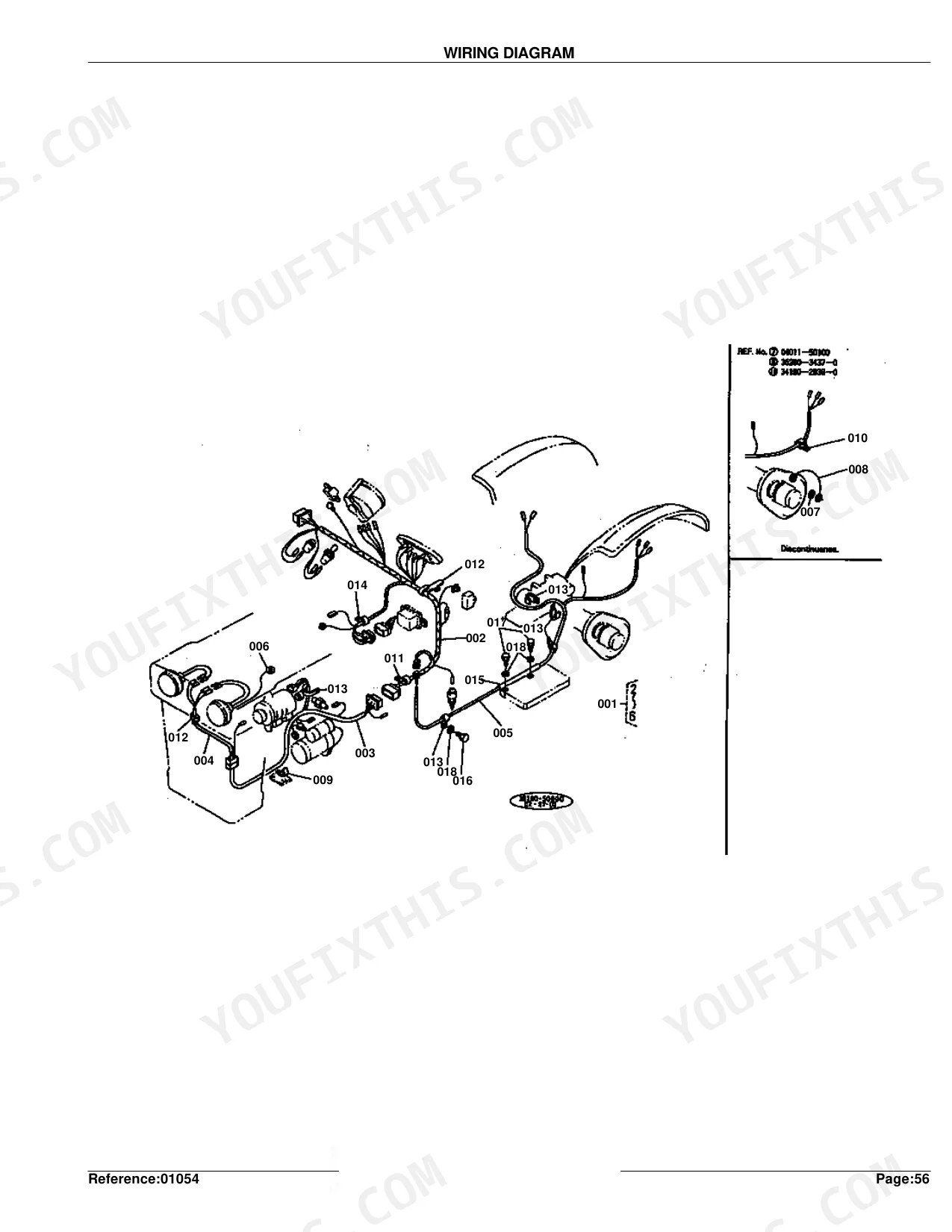
Yes. The catalog contains the L275 wiring diagram section, which lays out the electrical layout for tracing circuits and identifying electrical parts. p. 117
Does it cover 4WD front-axle parts?
Yes. The catalog details the 4WD front axle, including the front axle support and related 4WD driveline components, so you can identify parts for 4WD repairs. p. 175
Are the hydraulic and three-point hitch parts listed?
Yes. The oil hydraulic system sections and the three-point link parts are included, with reference numbers and Kubota part numbers for the lift and hitch components. p. 123
How quickly can I access this manual after buying?
Download arrives instantly. The full 262-page searchable Parts Manual is yours the moment payment clears, ready to open on a laptop, tablet, or phone right in the shop.
Can I print this manual?
Yes, and there's no DRM or copy protection. Print the whole manual or just the pages you need on any home or office printer.
Does this Kubota L275 manual include wiring diagrams?
Yes, but as a parts catalog this is a wiring diagram for ordering, not a workshop schematic. The electrical section identifies the wiring parts, switches, and connectors with their part numbers so you order the right ones. It does not carry wire-color circuit tracing or troubleshooting descriptions.

Reviews
There are no reviews yet.