
Part of the Kubota Parts Manuals.
This is the Kubota factory parts catalog for the TL420A front loader, the loader fitted to Kubota compact tractors such as the B20. Its 30 pages present exploded diagrams with reference numbers, Kubota part numbers, quantities, and serial ranges so you can identify each loader component before ordering.
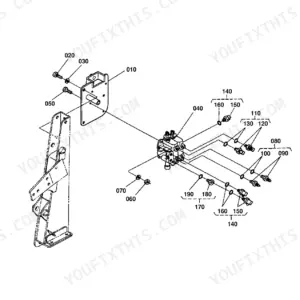
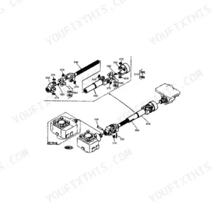
The catalog covers the full loader: the side frames and mounting, the boom and bucket, the control valve and its internal component parts, the control lever, cover, and linkage, the boom and bucket cylinders with their seal kits, and the hydraulic hoses, tubes, and delivery and return lines that feed them.
Loaders in this class are worked hard, so pins wear and cylinders and valves develop leaks. This catalog is the fast way to match seal kits, hoses, pins, and valve parts to your exact machine, avoiding the wrong number guesswork that makes hydraulic repairs drag on.
What's Inside This Kubota TL420A Parts Manual
| System | Pages | Key Topics |
|---|---|---|
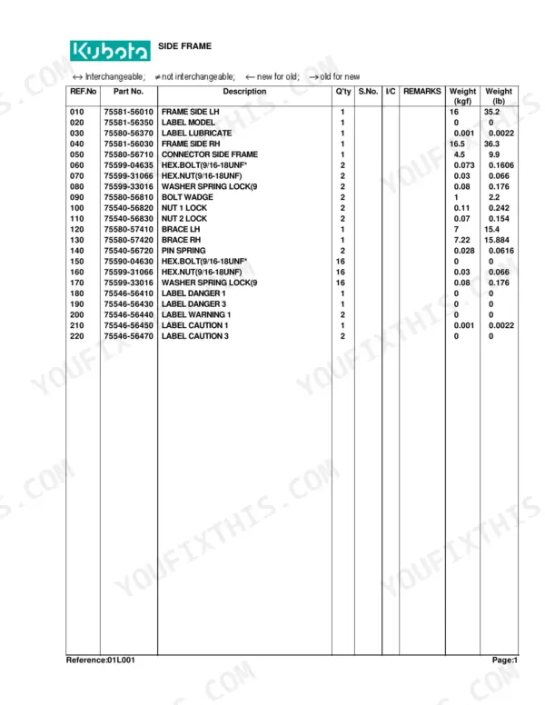
| Side Frame | 3-4 | Frame Side LH, Frame Side RH, Connector Side Frame, Brace LH, Brace RH, Hex.Bolt |
| Boom | 5-6 | Pin, Fitting Grease, Comp Link, Bucket, Edge Cutting |
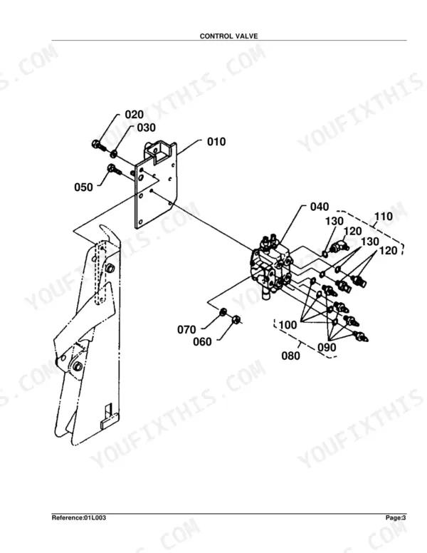
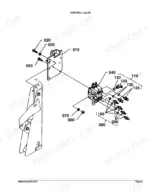
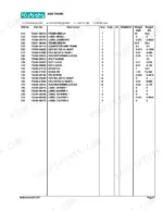
| Control Valve | 7-8 | Stay Valve, Hex.Bolt, Washer Spring Lock, Valve Control, Assy Adapter, O-Ring |
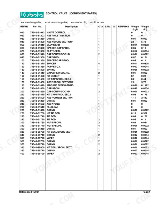
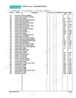
| Control Valve [Component Parts] | 9-10 | Valve Control, Assy Inlet Section, Assy Spool Section, Cap Spool, Kit Detent, Kit Tie Rod |
| Lever | 11-12 | Bushing, Collar, Cir-Clip External, Rod, Pin Cottre |
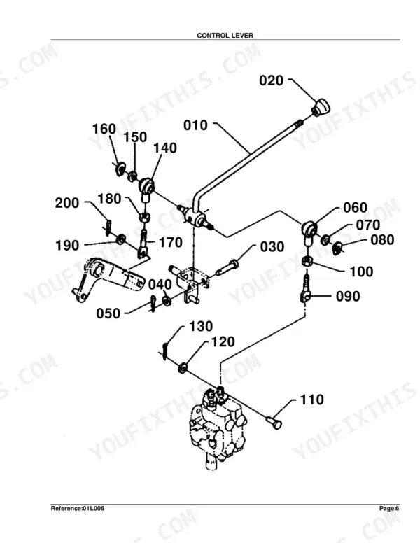
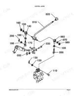
| Control Lever | 13-14 | Lever Control, Grip Lever, Pin Clevis, Joint Rod End, Hex.Jam Nut, Rod |
| Control Cover | 15-16 | Cover, Hex.Bolt, Washer Sprint Lock, Label Control, Assy Limiter, Cushion |
| Link | 17-18 | Bushing, Collar, Cir-Clip External, Rod, Hex.Jam Nut |
| Cylinder and Hydraulic Hose | 19-20 | Cylinder 1, Cylinder 2, Band Code, Hose 1 Hydraulic, Hose 2 Hydraulic, Hose 8 Hydraulic |
| Cylinder (Boom) [Component Parts] | 21-22 | Tube 1 Comp, Rod 1 Comp, Head 1, Piston 1, Kit 1 Seal |
| Cylinder (Bucket) [Component Parts] | 23-24 | Tube 2 Comp, Rod 2 Comp, Head, Piston, Kit Seal |
| Hydraulic Tube | 25-26 | Tube 1 Hydraulic, Tube 2 Hydraulic, Tube 3 Hydraulic, Tube 4 Hydraulic, Clamp 1, Clamp 2 |
| Delivery and Return Hose | 27-29 | Hose 5 Hydraulic, Hose 6 Hydraulic, Hose 7 Hydraulic, Band Code, Adapter, Joint |
| Accessories and Service Parts | 30 |
Quick Reference Specifications
| Specification | Value | Page |
|---|---|---|
| Hose 1 Hydraulic Length | 27.8 inches | p. 20 |
| Hose 2 Hydraulic Length | 29.3 inches | p. 20 |
| Hose 8 Hydraulic Length | 22.0 inches | p. 20 |
| Hose 9 Hydraulic Length | 41.5 inches | p. 20 |
| Hose 5 Hydraulic Length | 53.6 inches | p. 28 |
Kubota TL420A Common Problems This Manual Covers
Loader arms drift down
Boom arms that settle or will not hold position after shutdown usually mean worn rod seals inside the boom cylinder. This section breaks the cylinder into tube, rod, piston, head, and seal kit for a rebuild.
Manual Section: Cylinder (Boom) [Component Parts] p. 21Weak or slow boom function
One loader function that is slow or weak compared with the other can come from cylinder wear or a restricted or failing hose. This section identifies the cylinders and their hydraulic hoses.
Manual Section: Cylinder and Hydraulic Hose p. 19Hydraulic leak at hoses or fittings
Leaks around the loader often trace to failed hose ends or worn fittings on the supply and return lines. This diagram lists the hoses, adapters, and joints so you can order exact replacements.
Manual Section: Delivery and Return Hose p. 27Hard to diagnose valve or load check faults
When the loader will not hold or responds oddly, the control valve and its load check are common suspects. This section identifies the valve, stay, and mounting hardware.
Manual Section: Control Valve p. 7Loader will not raise after service
A loader that will not raise after reinstall often has trapped air or a valve issue. The valve component section breaks down the inlet and spool sections, detent, and tie rod kit for internal service.
Manual Section: Control Valve [Component Parts] p. 9Pin and bushing wear at the boom
Excessive play at the pivot points develops from wear at the side frame and boom joints. This section identifies the boom pins, links, and grease fittings that take the load.
Manual Section: Boom p. 5Frequently Asked Questions
Which machine does this manual cover?
It is the factory parts catalog for the Kubota TL420A front loader, a 30 page document with exploded diagrams and Kubota part numbers for that loader.
Does it include part numbers and exploded diagrams?
Yes. Every section pairs an exploded illustration with reference numbers, Kubota part numbers, quantities, and serial ranges, so you can identify and order the exact part.
Can I rebuild the boom cylinder with this catalog?
Yes. The boom cylinder component section breaks the cylinder into its tube, rod, head, piston, and seal kit, so you can order a full reseal for a drifting or leaking cylinder. p. 21
Does it identify the hydraulic hoses?
The cylinder and hydraulic hose section lists the loader hoses with their lengths, along with the tubes and fittings, so you can match a replacement to your machine. p. 19
What do I get after purchasing this Kubota TL420A manual?
A 30-page searchable PDF, ready to download the moment you buy. It works on any device, so you can pull it up on your phone right at the machine. No shipping, no waiting.
Is this Kubota TL420A Parts Catalog printable?
Yes. Printing works from any reader and any printer, for your own shop use.




Reviews
There are no reviews yet.