


Part of the Kubota Repair Manuals.
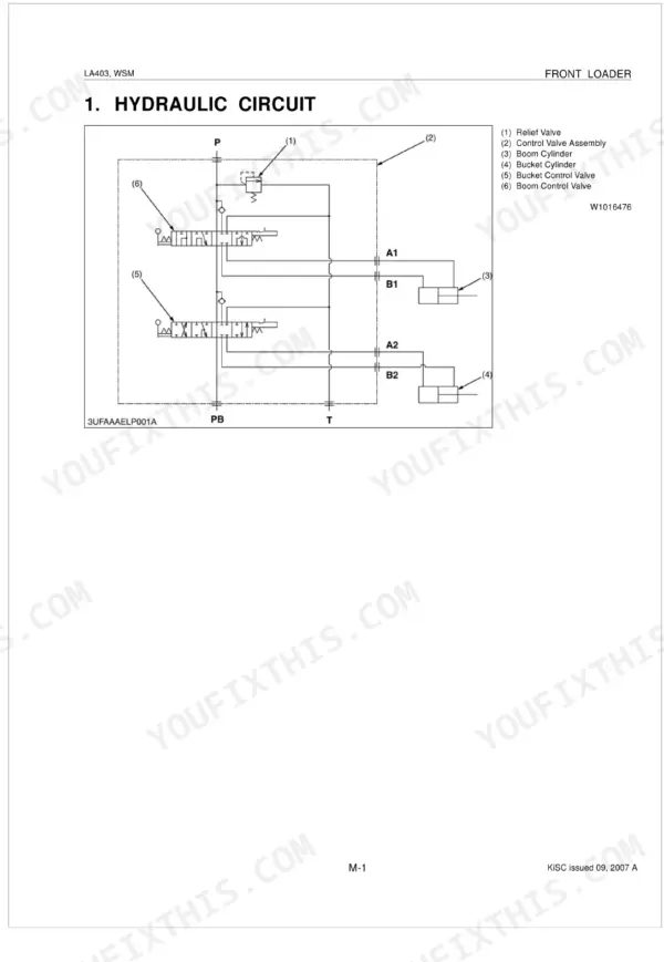
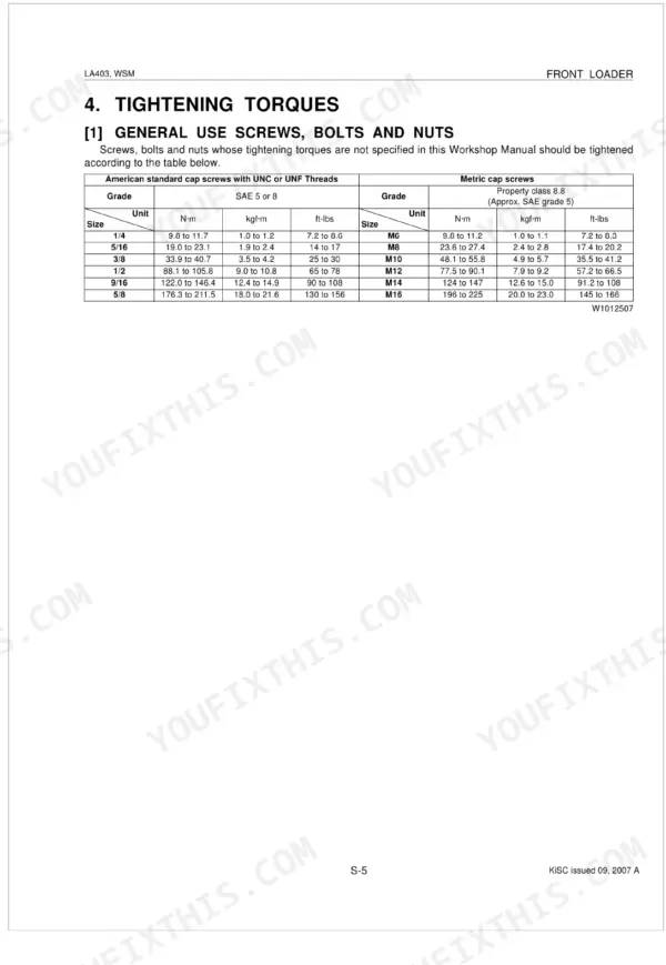
All 45 pages of this Kubota LA403 Workshop Manual focus on one machine: the LA403 Front Loader, from hydraulic circuit design to complete cylinder teardown. Inside, you get the full hydraulic block schematic with fluid routing through the control valve assembly, a troubleshooting guide covering pressure faults and cylinder drift, and step-by-step servicing procedures for the boom, bucket, and side frame. Torque the boom and bucket cylinder head to 237 to 305 N·m; snug the main frame M14 mounting bolts to exactly 147 N·m. Your loader is down and the internet has opinions, not specs. Download it once, search by keyword, hit a bookmark, and you are at the right spec before the wrench is cold.
Complete the set for your LA403
- Parts Catalog: Kubota LA403 Compact Tractor Loader Parts Catalog
What's Inside This Manual
| System | Pages | Key Topics |
|---|---|---|
| Safety Instructions | 3-7 | |
| Loader Terminology | 8 | Hydraulic Control Valve, Side Frame, Mounting Pin, Main Frame, Boom Cylinder, Boom, Bucket Cylinder, Bucket |
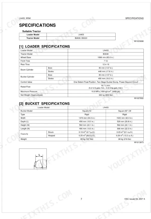
| Specifications | 9-10 | Loader Specifications, Bucket Specifications, Dimensional and Operational Specifications |
| Mechanism | 11-21 | Hydraulic Circuit, Hydraulic Block, Control Valve Assembly (Structure, Operation) |
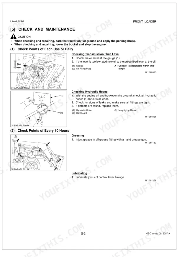
| Check and Maintenance | 23-24 | General |
| Servicing Specifications | 25-26 | Relief Valve, Piston Rod |
| Hydraulic Fittings | 27-28 | Tightening Torques |
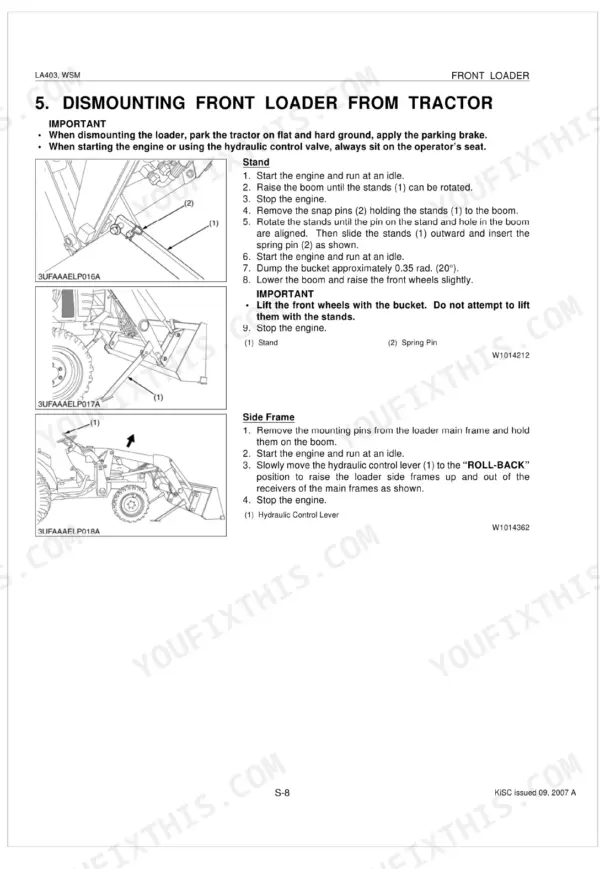
| Dismounting Front Loader From Tractor | 29-31 | Special Use Screws, Bolts and Nuts |
| Checking, Disassembling and Servicing | 32-36 | Control Valve, Hydraulic Hose, Control Lever, Control Cable, Adapter, Elbow |
| Controller | 37-38 | Control Lever Assembly, Rubber Boot, Control Lever Pivot, Cable End, Cable for Boom Section, Lever Lock, Cable for Bucket Section |
| Bucket, Boom and Hydraulic Cylinders | 39-41 | Bucket, Boom And Hydraulic Cylinders |
| Side Frame, Main Frame and Others | 42-45 | Servicing, Side Frame, Main Frame and Others |
Quick Reference Specifications
| Specification | Value | Page |
|---|---|---|
| General Use Screws, Bolts and Nuts (M6) | 9.8 to 11.2 N·m | p. 27 |
| Main frame mounting bolt (M14) torque | 147 N·m | p. 44 |
| Boom and bucket cylinder head torque | 237 to 305 N·m | p. 29 |
| Boom and Bucket cylinder piston mounting nut torque | 108 to 135 N·m | p. 29 |
| Hose fitting and flare nut (Steel, 9/16-18 thread size) torque | 24.3 to 27.0 N·m | p. 28 |
| Relief Valve Setting Pressure (B2630) | 16.3 to 16.6 MPa | p. 26 |
| Relief Valve Setting Pressure (B3030) | 16.2 to 16.5 MPa | p. 26 |
| Piston Rod Bend Allowable Limit | 0.25 mm | p. 26 |
| Transmission Case Capacity (Front loader not attached) | 15 L | p. 23 |
| Control valve cover mounting screw torque (M6) | 9.7 to 11.2 N·m | p. 29 |
| Control Lever Rod 1 length A | 115.3 to 116.3 mm | p. 33 |
| Control Cable Length L (Valve kit serial No.: below 20000) | 58.0 to 59.0 mm | p. 34 |