
Part of the Kubota Repair Manuals.
This is the Kubota Common Rail System Diagnosis Manual for the V3800-CR-TE4, V3800-CR-TIE4, V3800-CR-TE4C, and V3800-CR-TIE4C diesel engines, a 335 page PDF you download and keep. It focuses on the electronic fuel and control side of these engines: the high pressure common rail, injectors, supply pump, ECU, and the sensors that feed it.
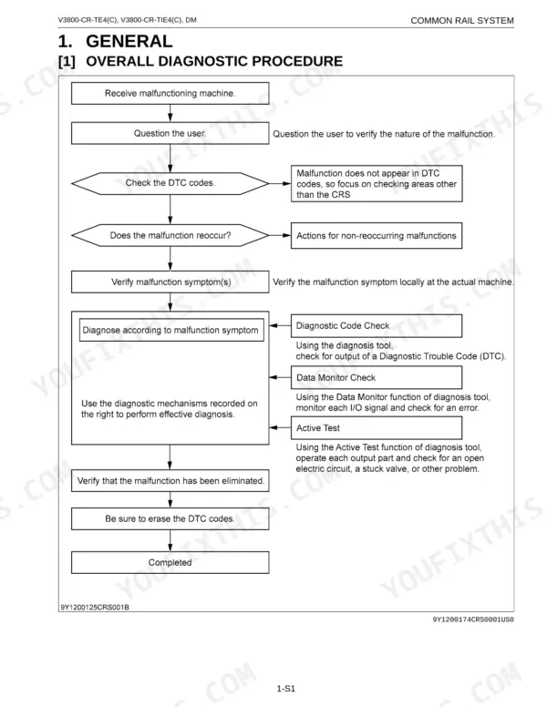
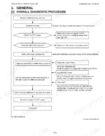
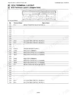
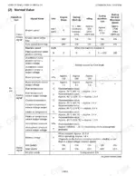
Inside you get wiring diagrams, ECU terminal layouts, data monitor signal values, and the full diagnostic tool connection procedure for Diagmaster and the DST-i interface. The core of the book is fault finding, diagnosis by malfunction symptom for problems like no start, rough idle, black or white smoke, and poor power, plus step by step diagnostic procedures for each DTC.
Use it to read codes, test injectors and the SCV, check rail pressure targets, and trace a running fault to the right component instead of guessing.
What's Inside This Kubota V3800 Series Manual
| System | Pages | Key Topics |
|---|---|---|
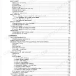
| Information | Contents (Safety First), Safety First, Before Servicing and Repairing, Safety Starting, Safety Working, Avoid Fires, Ventilate Work Area, Prevent Acid Burns | |
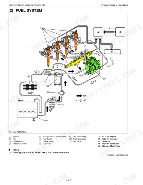
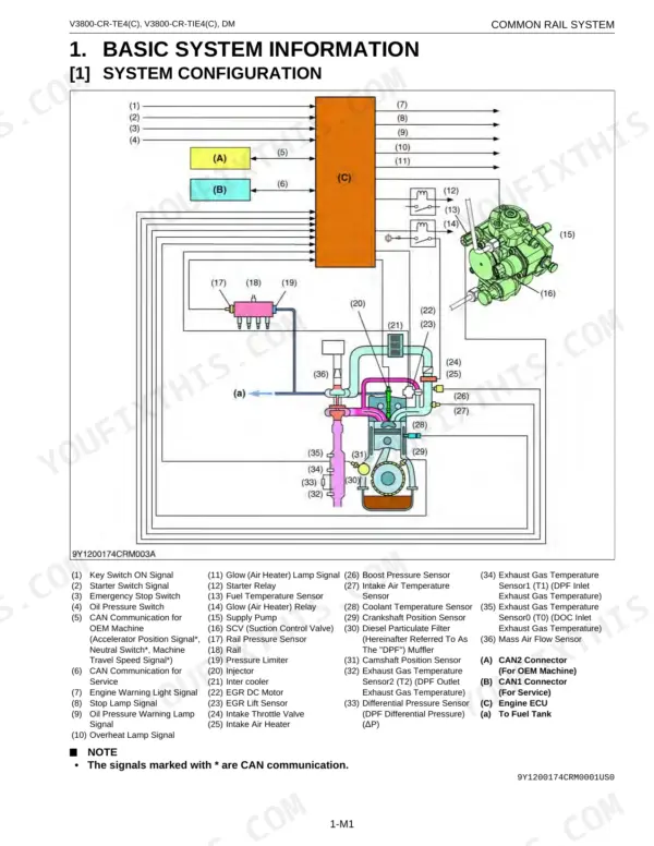
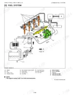
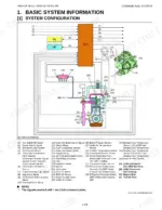
| Basic System Information | System Configuration, Fuel System Components, Intake and Exhaust System Components | |
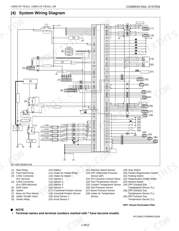
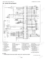
| Wiring Diagram | Engine Intermediate Harness, Injector Intermediate Harness, ECU Intermediate Harness, System Wiring Diagram | |
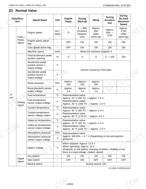
| Available Data Monitor Signals (Level 2) | Monitor Items, Normal Value, Pulse/Rotary Signal, Analog Signal, Digital Signal | |
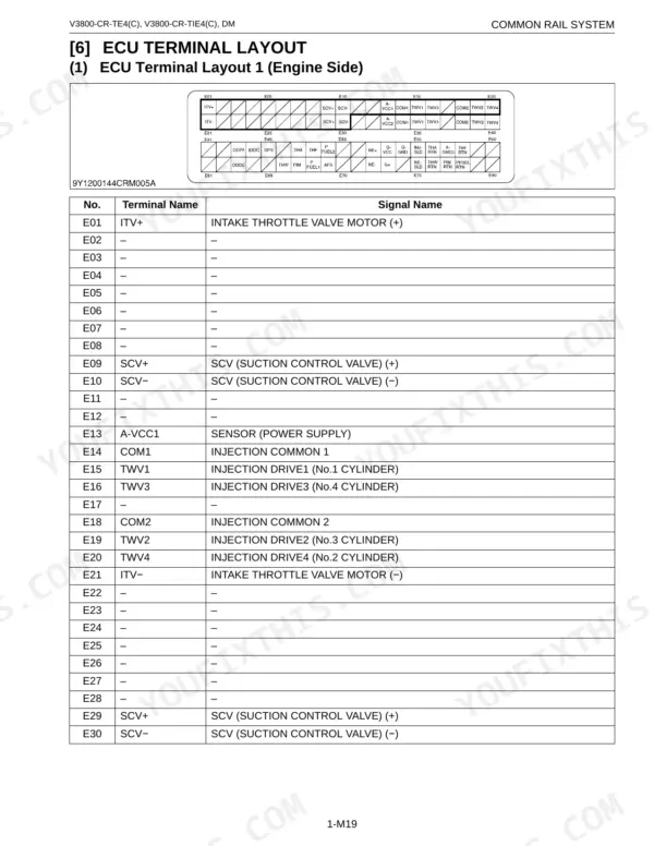
| ECU Terminal Layout | ECU Terminal Layout 1 (Engine Side), ECU Terminal Layout 2 (Machine Side) | |
| Diagnostic Tool Connection Procedure | Diagnostic Connector Positions, Checking the Communication Operation of the Interface, Checking the Operation of the ECU, Starting Diagmaster, DST-i Communication Settings | |
| Active Test and Supply Pump Difference Learning | Injector Non-Injection Instruction, EGR Actuation Test, Air Heater Relay Actuation Test, Supply Pump Difference Learning | |
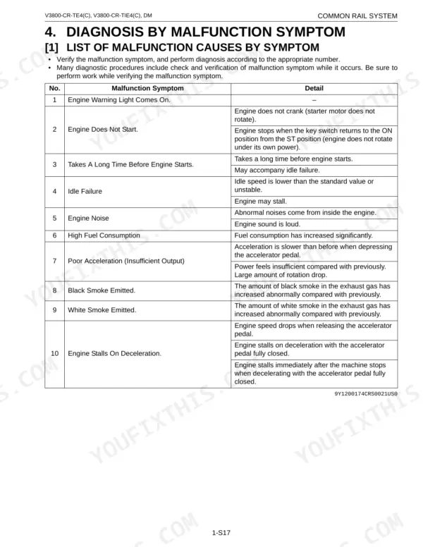
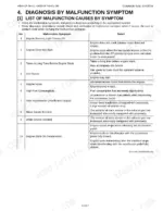
| Diagnosis by Malfunction Symptom | List of Malfunction Causes by Symptom, Engine Warning Light Comes on, Engine Does Not Start, Takes a Long Time Before Engine Starts, Idle Failure, Engine Noise | |
| Diagnostic Procedure by Dtc | Dtc List, Ne - G Phase Shift, Intake Air Temperature Built-In Maf Sensor: Abnormality, Pressure Limiter Emergency Open, High Rail Pressure, SCV Stuck, Fuel Leak | |
| Inspection Procedure for Each System | Air Intake System Inspection Procedure, Fuel System Inspection Procedure, Electric System Inspection Procedure, Basics of Checking Electrical / Electronic Circuit Systems |
Quick Reference Specifications
| Specification | Value | Page |
|---|---|---|
| Engine oil type | API Service Classification CF grade or higher | p. 40 |
| Fuel Cetane Rating (minimum) | 45 | p. 287 |
| Air cleaner element cleaning interval (Primary and Secondary) | Every 250 hours | p. 291 |
| Air cleaner element replacement interval | Once yearly or after every sixth cleaning, whichever comes first | p. 291 |
| Engine Speed (Idling) | 800 min-1 (rpm) | p. 24 |
| Engine Speed (No-load Maximum Speed) | 2700 min-1 (rpm) | p. 24 |
| Battery Voltage (Stopped) | 12.5 V | p. 24 |
| Battery Voltage (Operating) | 14 V | p. 24 |
| Target Rail Pressure (Idling) | 40 to 50 MPa | p. 25 |
| Target Rail Pressure (No-load Maximum Speed) | 95.0 to 115 MPa | p. 25 |
| Target Suction Control Valve (SCV) Current (Idling) | 1700 to 2000 mA | p. 25 |
| Intake Air Temperature Sensor Resistance (20 °C) | 2.43 kΩ | p. 150 |
Kubota V3800 Series Common Problems This Manual Covers
Engine cranks but will not start
Common rail engines can fail to start from a faulty supply pump, SCV, or injector circuit rather than an obvious mechanical fault. The diagnosis by symptom section isolates the cause step by step.
Manual Section: Engine Does Not Start p. 56Long crank before the engine fires
Slow starting often points to low rail pressure or a weak signal from a fuel side sensor. This section walks through the checks in order.
Manual Section: Takes A Long Time Before Engine Starts p. 60Rough idle or stalling
Unstable idle on these engines is commonly traced to injector balance, the SCV, or intake and sensor faults. The symptom procedure lists the likely causes to test first.
Manual Section: Idle Failure p. 64Black smoke under load
Heavy black smoke usually means an air, fuel, or injection fault. The manual ties the symptom to the intake and fuel system inspections that find it.
Manual Section: Abnormal Black Smoke Emitted p. 79White smoke at start or idle
White smoke can come from injection timing, a cold combustion issue, or a leaking injector. This section separates the causes for the common rail system.
Manual Section: Abnormal White Smoke Emitted p. 83Poor acceleration and low power
Insufficient output is diagnosed against rail pressure targets, boost, and injector delivery. The procedure points to the checks and data monitor values that confirm it.
Manual Section: Poor Acceleration (Insufficient Output) p. 74Rail pressure and SCV fault codes
A stuck suction control valve sets pressure related DTCs and can trigger the engine warning light. The DTC procedure gives the resistance checks and steps to confirm the SCV.
Manual Section: SCV Stuck (DTC P0089 / 1347-7) p. 161Frequently Asked Questions
Which engines does this manual cover?
It covers the Kubota Common Rail System on the V3800-CR-TE4, V3800-CR-TIE4, V3800-CR-TE4C, and V3800-CR-TIE4C diesel engines. It is a diagnosis manual focused on the electronic fuel injection and control system, not a full mechanical rebuild manual.
Does it include wiring diagrams and ECU pinouts?
Yes. The Wiring Diagram section shows the engine, injector, and ECU intermediate harnesses and the system wiring diagram, and the manual also gives the ECU terminal layouts for both engine and machine sides. p. 12
Can I use it with a diagnostic scan tool?
Yes. The Diagnostic Tool Connection Procedure covers connector positions, checking the DST-i interface, and starting Diagmaster, so you can read live data and run active tests such as injector cut and the EGR test. p. 43
Does it list diagnostic trouble codes?
Yes. The Diagnostic Procedure by DTC section opens with a full DTC list and then gives a step by step procedure for each code, including rail pressure, SCV, and sensor faults. p. 92
Is this Kubota V3800 Series Diagnostic Manual a digital download?
Checkout delivers a 335-page searchable PDF, downloadable right away. Open it on a laptop, tablet, or phone and carry it onto the shop floor.
Am I able to print pages from this Kubota V3800 Series manual?
Yes. Print the pages you need for the job in your own shop, and bin them when they get greasy.
Does this Kubota V3800 Series manual include wiring diagrams?
Yes. Full electrical schematics are included, with wire colors, connector locations, and circuit descriptions.




Reviews
There are no reviews yet.