


Part of the Kubota Parts Manuals.
This catalog tracks every component on the LA352 loader, from the chassis and main frame through the full hydraulic system. Exploded-view diagrams break down each major assembly: boom and bucket, the control valve with its component-level seal kits, the control lever linkage, and the hoses, tubes, and cylinders that drive the hydraulics. Every page carries part numbers, quantities, serial number applicability, country codes, and interchange notes, so matching a part to your machine takes seconds. The figures come straight from Kubota: the 3-position control valve (serial numbers through 19999) weighs 7.5 kgf, and individual hydraulic tubes run 0.425 to 0.45 kgf apiece. No more guessing at the counter. Bookmarks and full-text search let you jump to any assembly and pull the exact number before you call the dealer.
What's Inside This Kubota LA352 Parts Manual
| System | Pages | Key Topics |
|---|---|---|
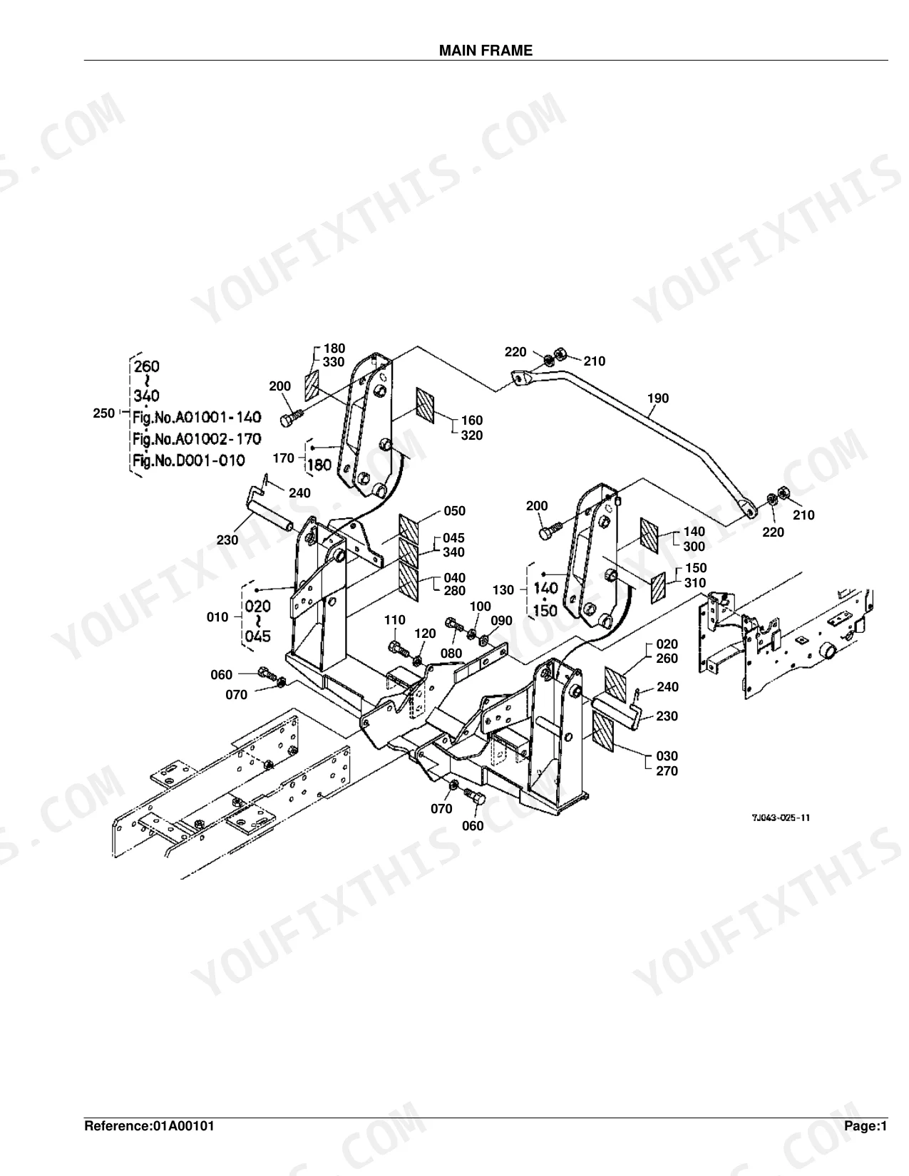
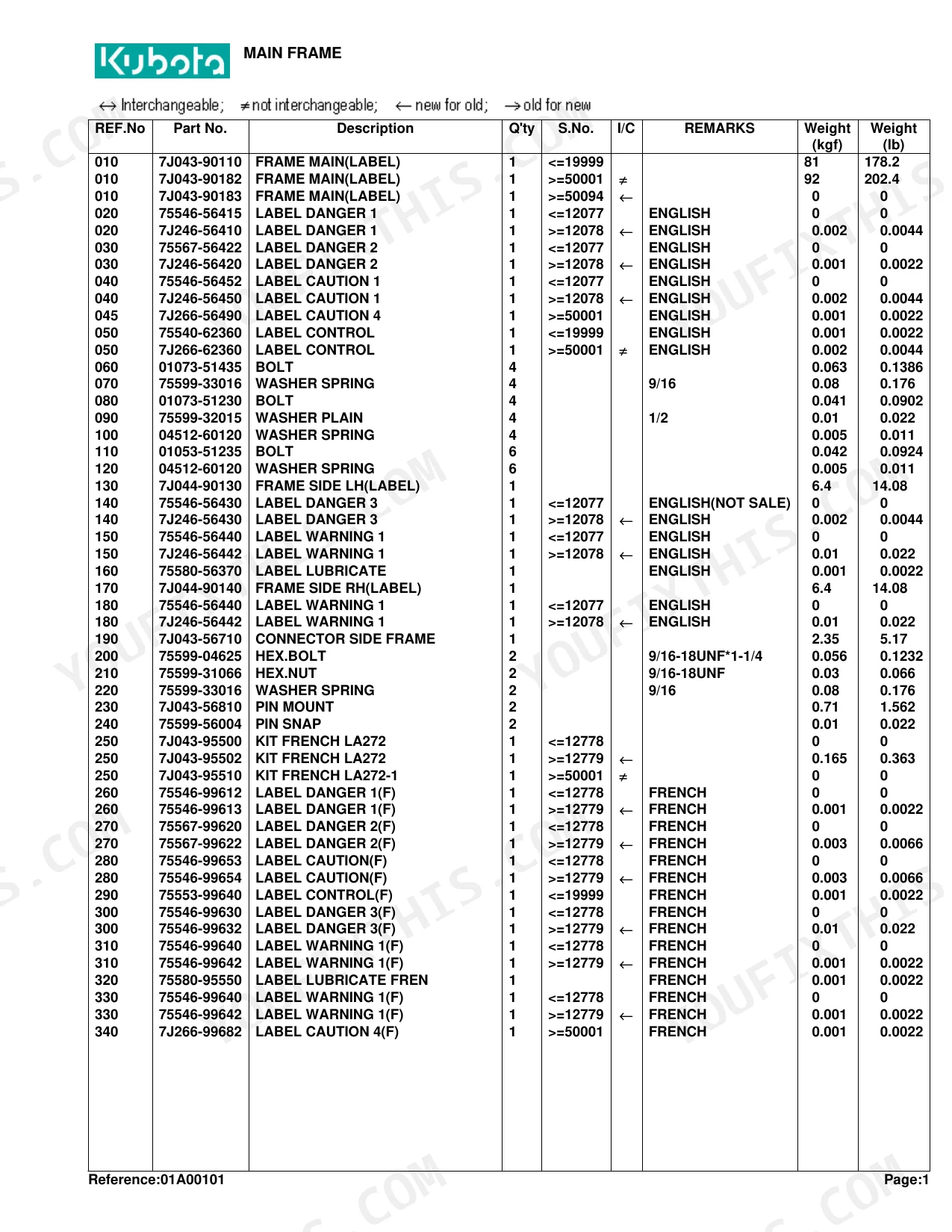
| Main Frame | 4-6 | Label Danger English, Label Caution English, Label Control English, Label Warning English, Label Lubricate English, Hex.bolt -18UNF -, Hex.nut -18UNF, Label Danger French |
| Brace | 7-8 | Hex.bolt -18UNF -, Hex.nut -18UNF, Guard Front, Cushion |
| Boom | 9-10 | Fitting Grease -27NPTF, Label Kubota, Fitting Grease -28T.T, Hex.bolt -20UNC -, Bucket, Edge Cutting, Label Leveler English, Label Leveler French French |
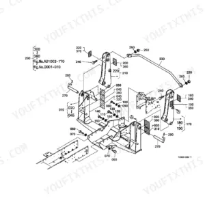
| Control Valve | 11-16 | Stay Valve, Hex.bolt -13UNC -, Assy Adapter, Assy Elbow Adjustabl, Elbow Adjustable, Nipple, Cap Dust, Valve Control B2009 |
| Control Valve [Component Parts] | 17-22 | Cap-Spool, Kit Detent Float, Assy Relief Valve, Cap Screw-soc.hd, Kit Load Check, Kit Seal, Kit Upper Boom Spool, Kit Upper Bkt Spool |
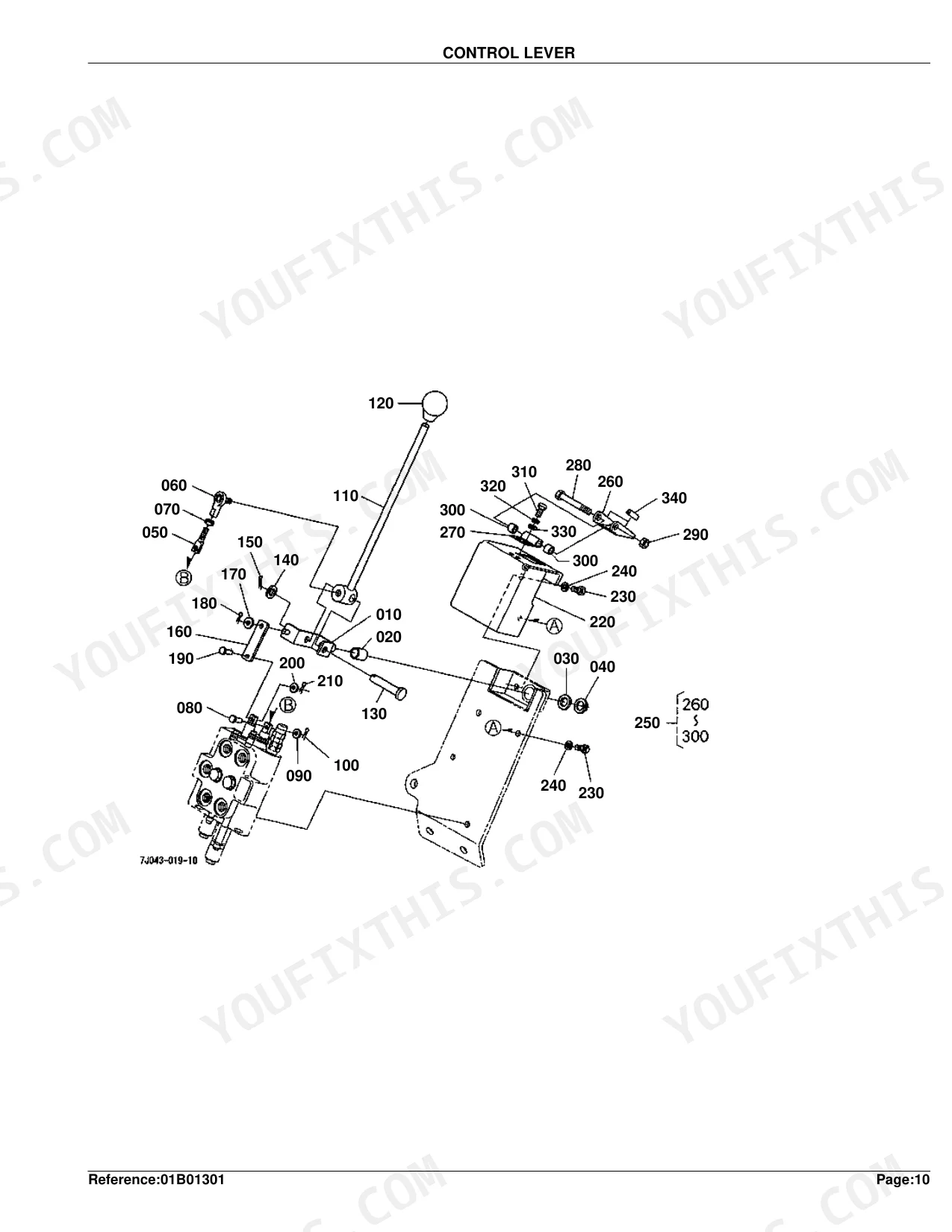
| Control Lever | 23-26 | Lever, Bushing, Collar, Rod, Joint Rod End, Lever Control, Grip Lever, Cover |
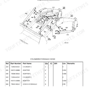
| Cylinder/Hydraulic Hose | 27-28 | Cylinder, Hose Hydraulic, Band Code |
| Hydraulic Hose(Hyd.Outlet Block) | 29-30 | Hose Hydraulic, Coupler, Sleeve, Band Code |
| Hydraulic Tube | 31-32 | Tube 1 Hydraulic, Tube 2 Hydraulic, Tube 3 Hydraulic, Tube 4 Hydraulic, Clamp |
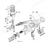
| Cylinder (Boom)[Component Parts] | 33-34 | Cylinder, Tube, Rod, Head, Piston, Kit Seal, Fitting Grease 90DEG, Fitting Grease -27NPTF |
| Cylinder (Bucket)[Component Parts] | 35-36 | Cylinder, Tube, Rod, Head, Piston, Kit Seal, Fitting Grease -27NPTF |
| Hydraulic Block | 37-41 | Adapter, Band Code, Block Hydraulic, Hose Hydraulic |
| Accessories and Service Parts | 42 | Operator's Manual |
Quick Reference Specifications
| Specification | Value | Page |
|---|---|---|
| TUBE 1 HYDRAULIC weight | 0.425 kgf | p. 32 |
| TUBE 2 HYDRAULIC weight | 0.425 kgf | p. 32 |
| HOSE 8 HYDRAULIC weight | 0.25 kgf | p. 28 |
| HOSE 9 HYDRAULIC weight | 0.26 kgf | p. 28 |
| VALVE CONTROL weight (S.No.;<=19999;[3 POSITION VALVE TYPE]) | 7.5 kgf | p. 12 |
| VALVE CONTROL weight (S.No.;<=19999;[4 POSITION VALVE TYPE]) | 4 kgf | p. 14 |
| PIN 1 weight | 0.365 kgf | p. 10 |
| PIN 2 weight | 0.425 kgf | p. 10 |
| EDGE CUTTING weight | 11 kgf | p. 10 |
| FRAME MAIN(LABEL) weight | 81 kgf | p. 6 |
| WASHER SPRING size | 9/16 | p. 6 |
| HEX.BOLT size | 9/16-18UNF*1-1/4 | p. 6 |
Kubota LA352 Common Problems This Manual Covers
Bent steel hydraulic lines across the front of the LA352 after pushing brush
Check the Hydraulic Tube diagram on page 31 to pin down which line bent. Confirm the replacement number for Tube 1 Hydraulic or Tube 2 Hydraulic, each listed at 0.425 kgf. If the clamps took damage too, cross-reference their part numbers.
Manual Section: Hydraulic Tube p. 31Excessive slop and play in the loader arms from worn pivot pins and bushings
Inspect the Boom exploded view on page 9 to locate the correct pivot pins, then match the worn parts against the list on page 10. Order replacement Pin 1, listed at 0.365 kgf, with the matching 9/64*1 cotter pins.
Manual Section: Boom p. 9Loader won't raise or lower properly after a severe impact
Review the Control Valve diagram on page 11 for cracked or damaged housings. Pull the complete valve assembly number from page 12. Decide whether you need the 3-position valve (7.5 kgf) or just individual adapter fittings and o-rings.
Manual Section: Control Valve p. 11Worn bucket cutting edge leaving uneven ground and struggling to bite into hard dirt
Locate the bucket breakdown in the Boom section diagram on page 9. Find the cutting edge part number on page 10. Note the new edge weighs 11 kgf, then add the required mounting bolts to your order.
Manual Section: Boom p. 9Frequently Asked Questions
What are the replacement specifications for steel hydraulic lines?
Steel hydraulic lines are listed under the 'HYDRAULIC TUBE' section. The four part numbers are TUBE 1 HYDRAULIC (7J043-65110) at 0.425 kgf (0.935 lb), TUBE 2 HYDRAULIC (7J043-65210) at 0.425 kgf (0.935 lb), TUBE 3 HYDRAULIC (7J043-65310) at 0.45 kgf (0.99 lb), and TUBE 4 HYDRAULIC (7J043-65410) at 0.45 kgf (0.99 lb). p. 32
What are the replacement specifications for hydraulic hoses?
Hydraulic hoses appear in the 'CYLINDER/HYDRAULIC HOSE' and 'HYDRAULIC HOSE(HYD.OUTLET BLOCK)' sections. Examples: HOSE 8 HYDRAULIC (75532-66610) at 0.25 kgf (0.55 lb), HOSE 9 HYDRAULIC (75536-66620) at 0.26 kgf (0.572 lb), and HOSE 1 HYDRAULIC (75532-66110) at 0.25 kgf (0.55 lb). p. 28
How quickly can I access this manual after buying?
Instant PDF download. The full 42-page searchable Parts Catalog is available the moment your payment clears. Open it on a laptop, tablet, or phone right in the shop.
Is this Kubota LA352 Parts Catalog printable?
No restrictions at all. Print individual pages, full chapters, or the entire manual. The PDF is completely unlocked.


Reviews
There are no reviews yet.