


Part of the Kubota Parts Manuals.
This is the factory parts catalog for the Kubota M4050 tractor, a 195 page reference organized by system with exploded diagrams matched to Kubota part numbers, quantities and serial number ranges. It also carries the M4050DT variant callouts, so front axle and drive parts are identified alongside the shared assemblies.Use it to find the exact replacement part before ordering. Each system, from crankcase, cylinder, injection pump and radiator through clutch, transmission, front and rear axle, steering, brake, hydraulics and electrical, gives a picture page with reference numbers next to its part number page.For owners and independent mechanics restoring an older Kubota, it removes the guesswork of matching worn components to the correct part numbers when the right parts can be difficult to source.
What's Inside This Kubota M4050 Parts Manual
| System | Pages | Key Topics |
|---|---|---|
| Clutch & Transmission | Clutch Housing, Transmission, Clutch, Clutch Pedal, 1, Shift Lever, Shift Fork | |
| Fuel System | Air Cleaner, Nozzle Holder, Governor, Injection Pump, Nozzle Holder 2, Fuel Tank 1, Fuel Tank 2 | |
| Cooling System | Radiator, Water Pump, Radiator Support | |
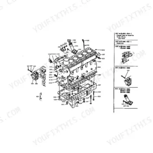
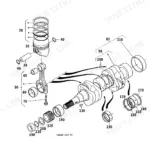
| Engine | Crankcase, Gear Case, Bearing Case, Muffler, Head Cover, Crankshaft, Flywheel, Oil Filter 2, Bearing Support Change Lever, Oil Pump, Oil Pump Cylinder Liner, Oil Pump Arm Shaft | |
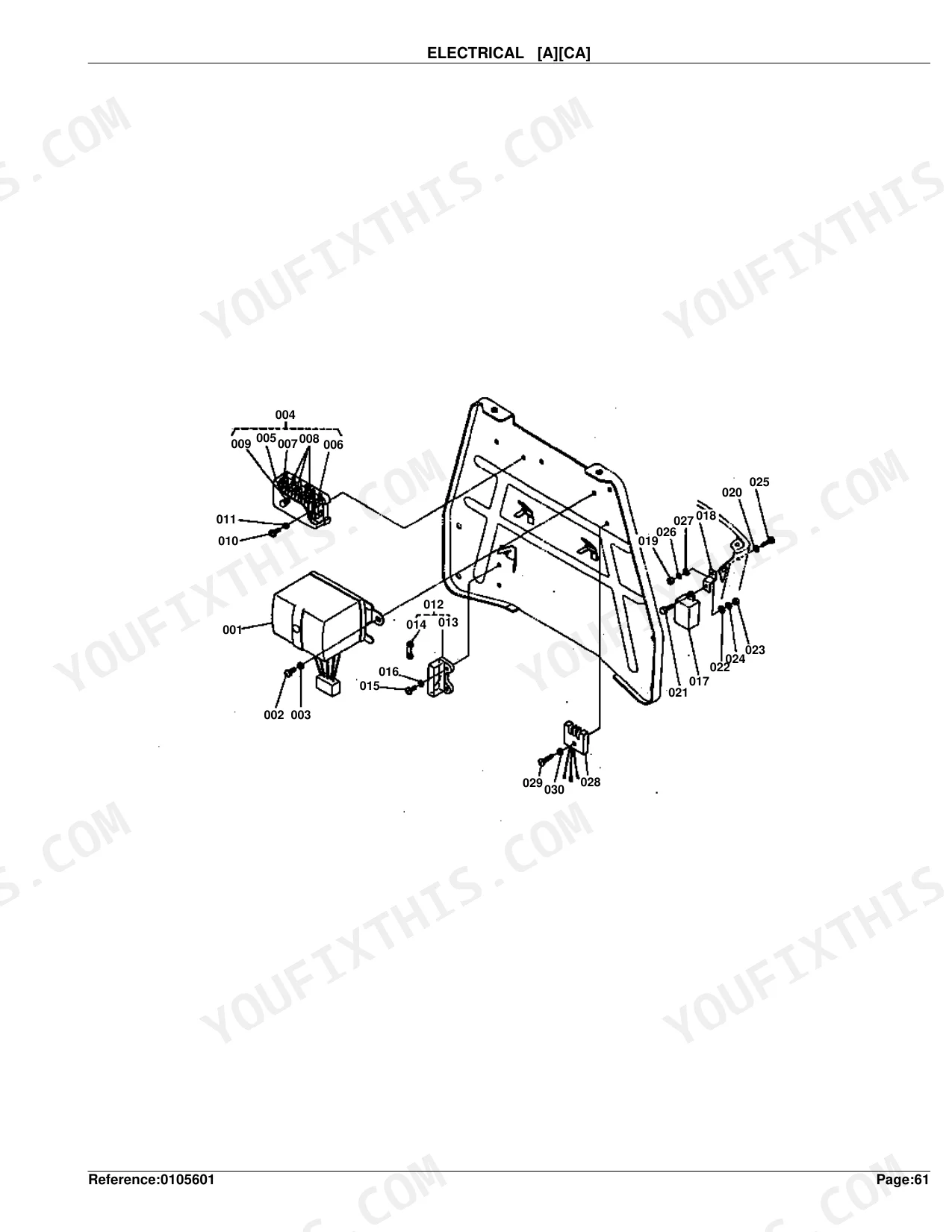
| Electrical System | Dynamo, Starter, Electrical, Battery, Main Switch, Panel Board, Lamp, Wire Harness | |
| PTO | PTO Shaft, PTO Cover | |
| Rear Axle, Differential & Brakes | Axle Case, Rear Axle, Rear Wheel, Brake, Brake Pedal, Hand Brake | |
| Front Axle & Steering | Front Axle, Bevel Pinion, Front Wheel Hub, Knuckle Shaft, Steering, Power Steering 1, Power Steering 2, Front Axle Middle | |
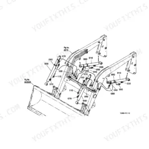
| Hydraulics & 3-Point Hitch | Cylinder, Valve, Top Link, Control Valve 1, Control Valve 2, Towing Drawbar, 3-Point Link 1, 3-Point Link 2, 3-Point Link 3 | |
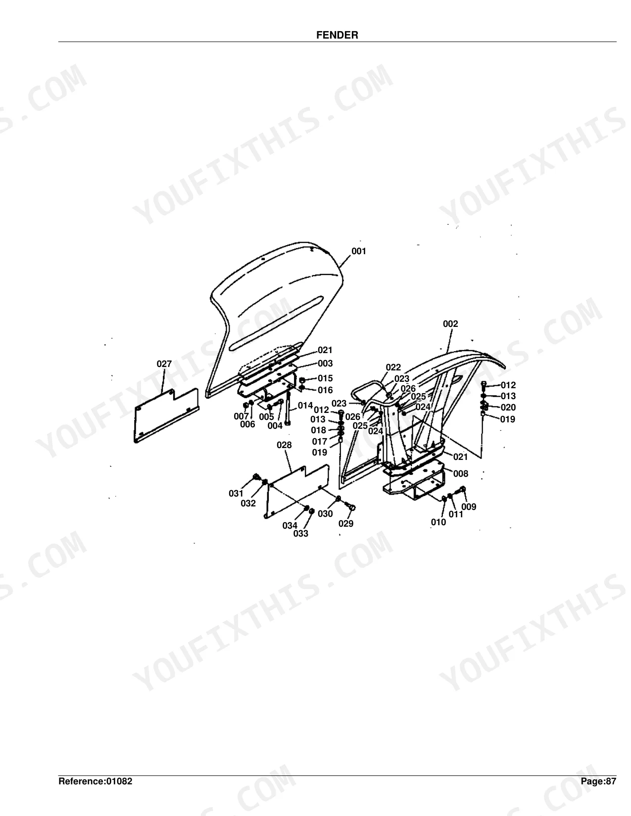
| Body & Operator Station | Change Cover, Bonnet 1, Bonnet 2, Bonnet 3, Fender, Step | |
| Decals & Accessories | Name Plate, Accessory and Service Parts | |
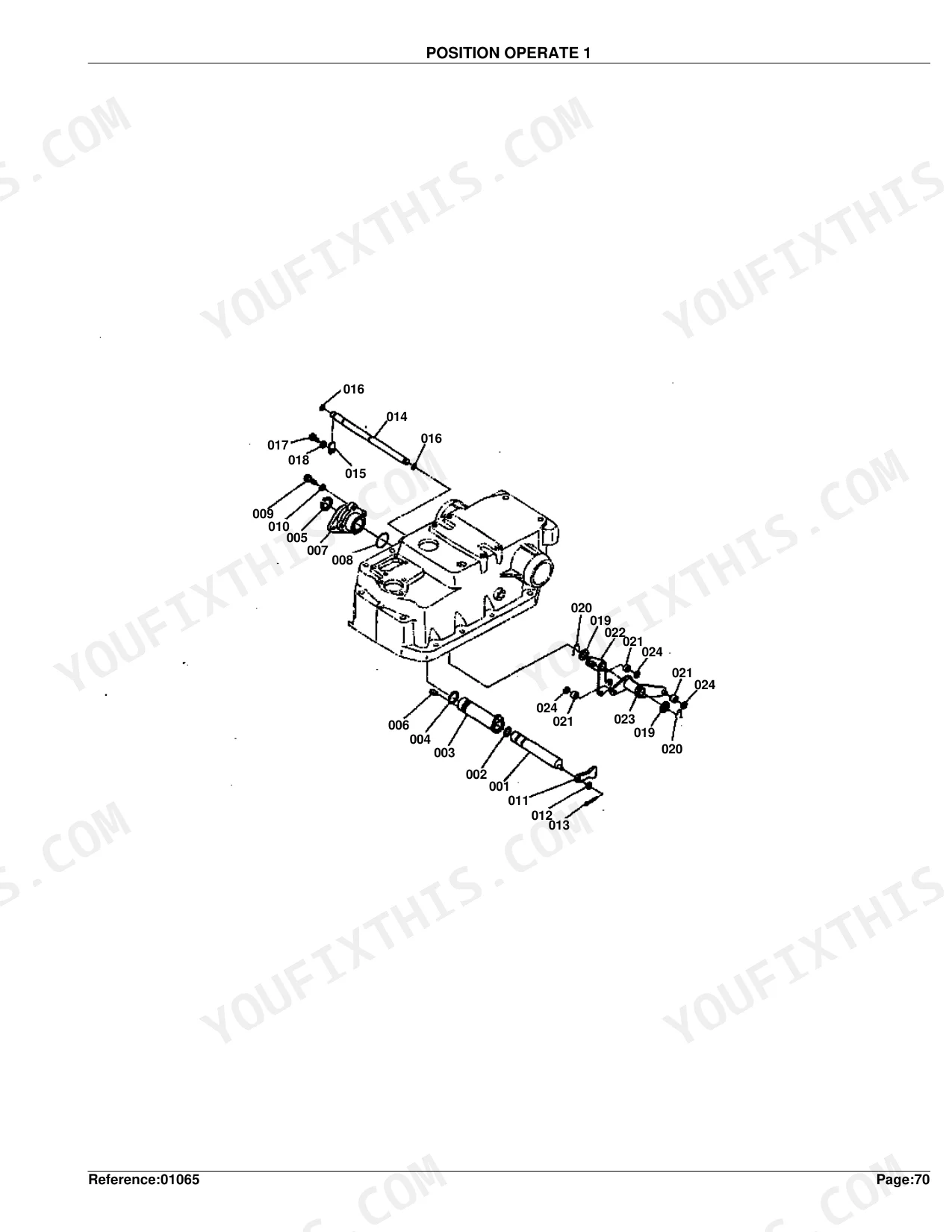
| Other Components | Accel Rod, Hand Accel, Lever, Mission Gear 1, Mission Gear 2, Mission Gear 3, Main Change Lever, Diff Support, Diff Lock, Booster, Position Operate 1, Position Operate 2, Position Operate 3, Position Operate 4, Position Operate 5, Filter Case |
Quick Reference Specifications
| Specification | Value | Page |
|---|---|---|
| Piston Oversize | +0.5MM | p. 27 |
| Crank Pin Metal Undersize | -0.2MM | p. 27 |
| Nozzle Holder Adjusting Washer Thickness | 1.00MM | p. 31 |
Kubota M4050 Common Problems This Manual Covers
No-start or intermittent starting
Starter, brush and magnet switch wear are common causes of slow or failed cranking on an older M4050. The starter section exploded the yoke, armature, brush holder and switch parts for repair sourcing.
Manual Section: Starter [Section Parts] p. 48Transmission or drivetrain wear
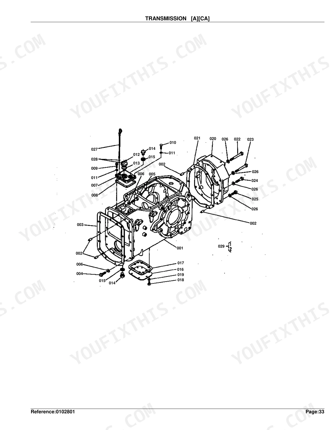
Grinding, slipping or loss of drive point to worn gears, shafts or bearings inside the transmission. The transmission section diagrams the case, cover and internal hardware for accurate part identification.
Manual Section: Transmission [A][Ca] p. 70Clutch slipping or hard shifting
A worn clutch disk, pressure plate or PTO clutch causes slipping and difficult gear changes. The clutch section lists the disk, plate, cover and kit parts for a full rebuild.
Manual Section: Clutch p. 74Overheating and coolant loss
A blocked radiator, failed drain cock or leaking water flange raises running temperature. The radiator section covers the assembly, net, water pipe and band parts for replacement.
Manual Section: Radiator p. 38Fuel delivery and rough running
Worn injection pump elements, delivery valves and adjusting shims cause hard starting and rough running under load. The injection pump section identifies the internal components and shims.
Manual Section: Injection Pump p. 42Charging system failure
A failing dynamo leaves the battery undercharged and can cause no-start conditions. The dynamo section breaks out the assembly, support and mounting hardware so you can order the right charging parts.
Manual Section: Dynamo p. 36Frequently Asked Questions
Which tractor does this catalog cover?
It covers the Kubota M4050 and carries the M4050DT variant callouts, so both the two-wheel-drive machine and the four-wheel-drive front axle parts are identified within the same catalog.
Is this a repair manual or a parts catalog?
It is a parts catalog. It provides exploded diagrams, reference numbers, Kubota part numbers, quantities and serial number ranges for identifying and ordering parts. It does not contain repair or torque procedures.
Where do I find the front axle parts?
The Front Axle section covers the front drive and steering components with reference numbers matched to part numbers, so you can order the correct axle parts for your machine. p. 72
Can it help me identify the correct oil filter cartridge?
Yes. The oil filter section exploded the cover, relief valve, O ring and cartridge, so you can match the filter cartridge and related parts to their Kubota part numbers. p. 46
How quickly can I access this manual after buying?
A 195-page parts catalog in searchable PDF format, yours the moment checkout completes. Open it on a computer, tablet, or phone, with no shipping wait.
Is this Kubota M4050 Parts Catalog printable?
The PDF is DRM-free, so print whatever sections you need to take to the shop. Standard letter or A4 paper works fine.


Reviews
There are no reviews yet.