



Part of the Kubota Parts Manuals.
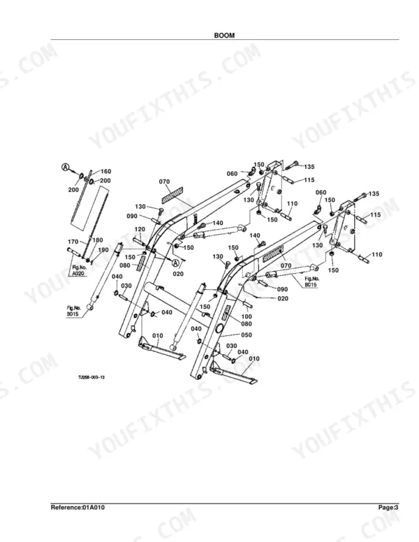
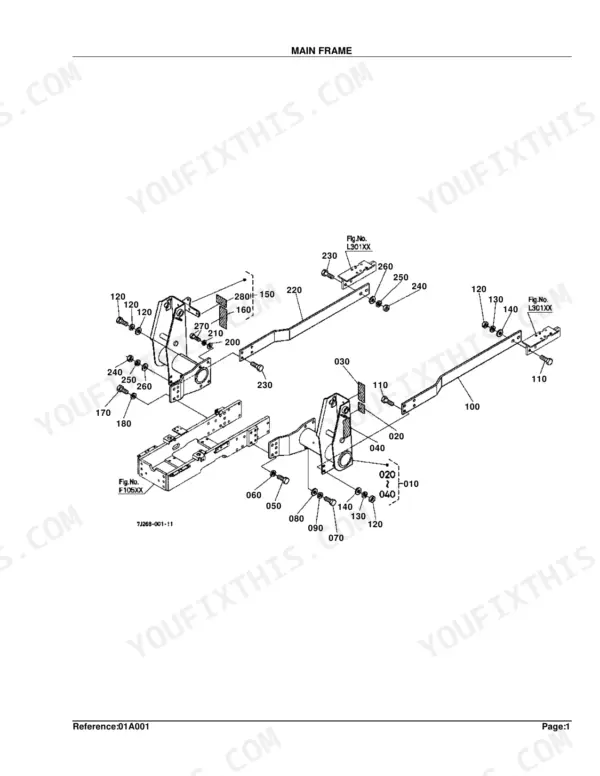
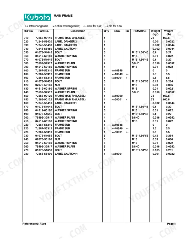
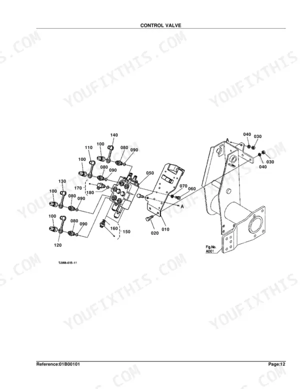
This is the factory parts catalog for the Kubota LA853 front loader, a 66 page reference organized by system with exploded diagrams matched to Kubota part numbers, quantities and serial number ranges. It covers the loader itself, from the main and side frame through the boom, bucket, quick bucket, control valve, control lever and full hydraulic circuit.
Use it to identify the exact replacement part before ordering. Each section pairs a picture page carrying reference numbers with a part number page, and the optional quick hitch, pallet fork and bale spear attachments are broken out separately.
For owners and independent mechanics servicing a loader that leaks, drifts or will not latch, it removes the guesswork of matching worn cylinders, hoses, valves and pins to the correct part numbers.
Complete the set for your LA853
- Operator Manual: Kubota LA513, LA723, LA853 Front Loader Operator Manual
- Repair Manual: Kubota LA513, LA723, LA853 Front Loader Workshop Manual
What's Inside This Parts Manual
| System | Pages | Key Topics |
|---|---|---|
| Main Frame | 4-5 | Figure L301XX, Figure F105XX |
| Side Frame | 6-7 | Figure A001, Figure F105XX |
| Boom | 8-9 | Figure A020, Figure B015 |
| Bucket Link | 10-11 | Figure A010, Figure A025XX |
| Bucket | 12-15 | Figure A010, Option, L2293 Blade, Bolt on Option |
| Quick Bucket | 16-25 | Figure C005, Figure A010, L2236 |
| Control Valve | 26-34 | Figure A001, S.No.;>=50001 Remote Valve Type |
| Control Valve [Component Parts] | 35-40 | Control Valve Component Parts Diagram, Control Valve Component Parts List, 3P Type (L2203), S.No., <=19999 4P Type (L2213/L2223), >=50001 4P Type (L2213/L2223) |
| Control Lever | 41-45 | Figure B001XX, Figure M101, Old Parts, Remote Valve Type |
| Cylinder/Hydraulic Hose | 46-47 | Cylinder/Hydraulic Hose Diagram, Figure A010, Figure A025XX, Cylinder/Hydraulic Hose Parts List |
| Hydraulic Hose(Hyd.Outlet Block) | 48-51 | Hose 5 Hydraulic, Hose 6 Hydraulic, Hose 7 Hydraulic, Band Code, Sleeve, Block Hydraulic |
| Hydraulic Tube | 52-54 | Figure B001, Figure A010, Old Part |
| Cylinder (Boom) [Component Parts] | 55-56 | Cylinder (Boom) Component Parts Diagram, Cylinder (Boom) Component Parts List |
| Cylinder (Bucket) [Component Parts] | 57-58 | Cylinder (Bucket) Component Parts Diagram, Cylinder (Bucket) Component Parts List |
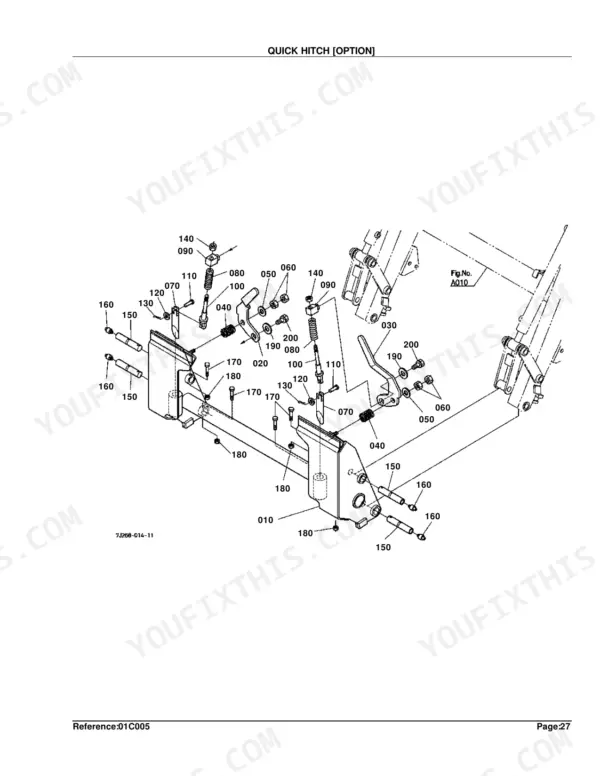
| Quick Hitch [Option] | 59-60 | Hitch Quick La853, Handle Latch LH, Spring Handle, Pin Latch, Link Latch Pin, Pin Joint |
| Pallet Fork [Option] | 61-62 | Pallet Fork Option Diagram, Figure C005, Figure A010, Pallet Fork Option Parts List, L2238 |
| Bale Spear [Option] | 63-65 | Bale Spear Option Diagram, Figure C005, Figure A010, Bale Spear Option Parts List, L2237, Accessories and Service Parts Diagram |
| Accessories and Service Parts | 66 | Operator's Manual, Kit French |
Quick Reference Specifications
| Specification | Value | Page |
|---|---|---|
| Bolt Size | M16*1.50*45 | p. 5 |
| Fitting Grease Angle | 90DEG. | p. 9 |
| Fitting Grease Thread | 1/4-28T.T. | p. 11 |
| Plow Bolt Size | 1/2-13UNC*1-3/4 | p. 15 |
| Control Valve Bolt Size | M12*1.25*30 | p. 27 |
| Assy Cable Length | 1700 | p. 45 |
| Cylinder (Boom) Nut Size | 5/8-18UNFP | p. 56 |
| Quick Hitch Bolt Size | M12*1.25*25 | p. 60 |


