


Part of the Kubota Parts Manuals.
Need the exact part number for your Kubota L4400H? The factory parts catalog maps every component across 312 pages, from the crankcase and injection pump through the HST drivetrain, rear differential, and 3-point hydraulic linkage. You'll work from 309 pages of parts lists, each paired with an exploded-view diagram, covering everything from crankcase internals to optional auxiliary control valve kits. Switches, sensors, relays, and wiring harness components are all called out by catalog number, and 15 pages of hydraulic parts cover pump internals, steering cylinder seal kits, and PTO oil line pieces. Replacing a piston? The +0.25mm oversize and -0.40mm/SET undersize crankpin bearing are both listed, so you order the right grade on the first call. No more digging through binders at the parts counter. Bookmarks let you jump to any assembly in seconds and carry the whole catalog to the machine on your phone.
What's Inside This Kubota L4400H Parts Manual
| System | Pages | Key Topics |
|---|---|---|
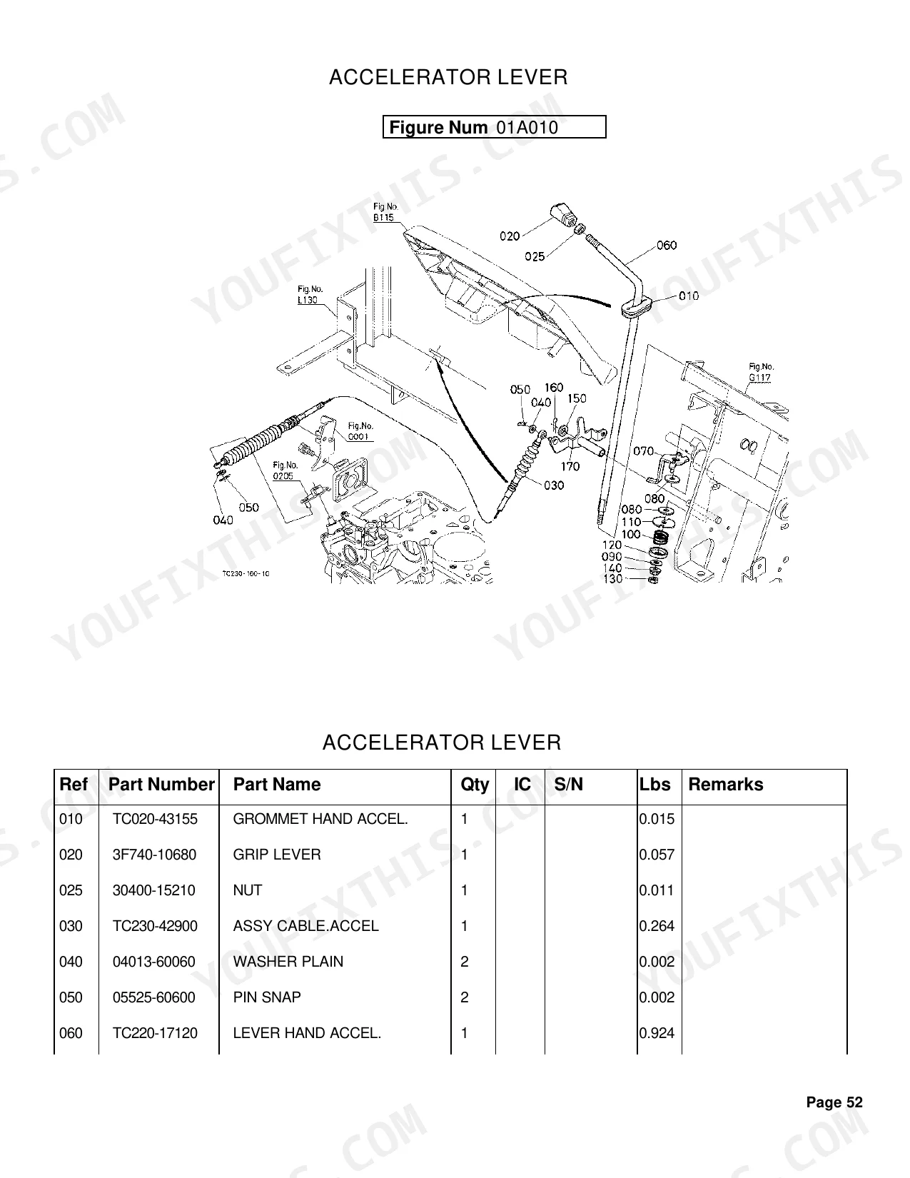
| Fuel System | Fuel Camshaft, Engine Stop Lever, Injection Pump, Governor, Speed Control Plate, Nozzle Holder and Glow Plug, Nozzle Holder, Air Cleaner, Accelerator Lever, Fuel Tank, Fuel Pipe and Fuel Filter, Fuel Filter, Speed Control Pedal | |
| Cooling System | Water Flange and Thermostat, Water Pump, Fan, Water Pipe, Radiator, Reserve Tank | |
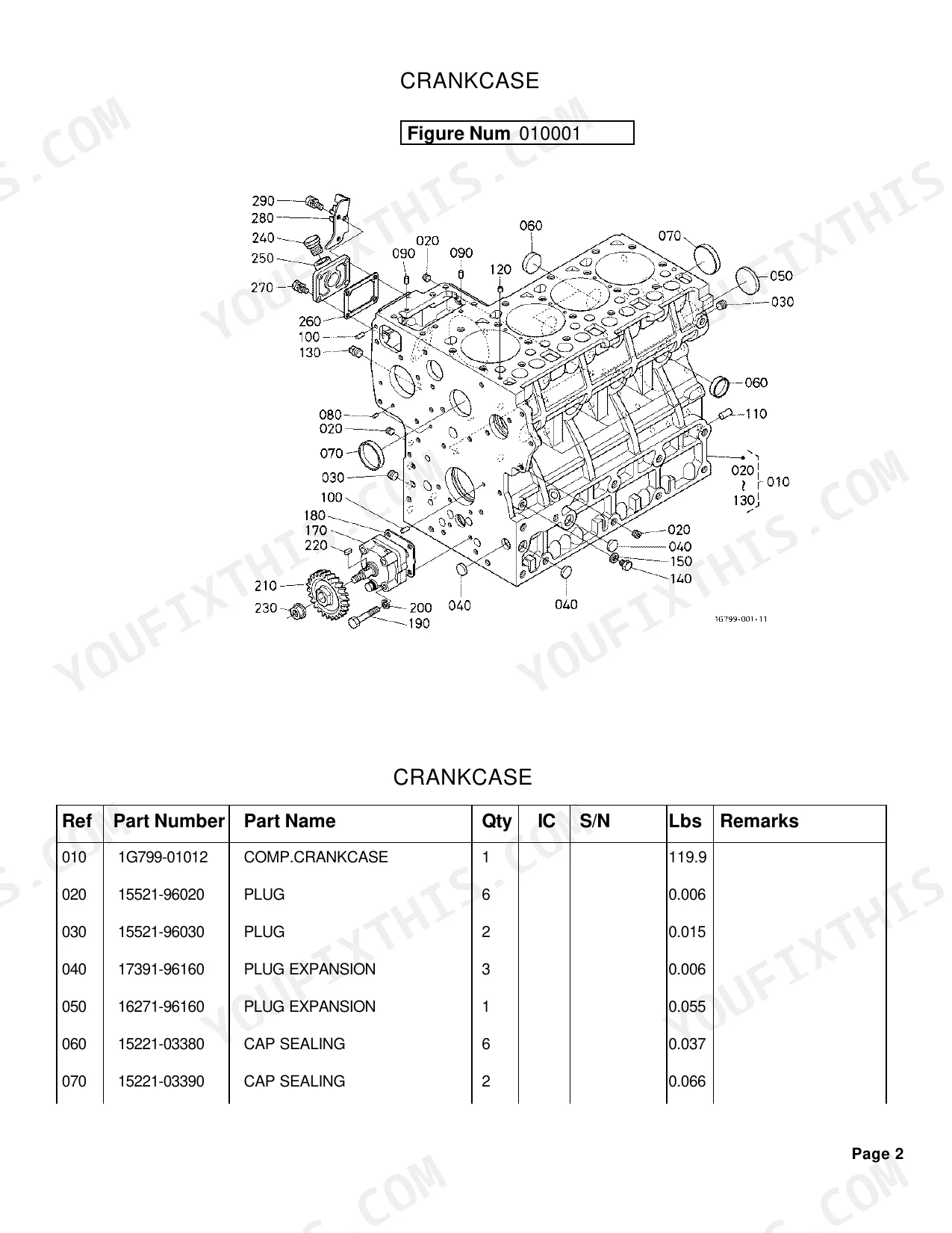
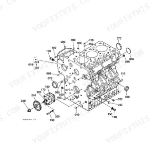
| Engine | Crankcase, Oil Pan, Cylinder Head, Gear Case, Main Bearing Case, Camshaft and Idle Gear Shaft, Piston and Crankshaft, Flywheel, Valve and Rocker Arm, Inlet Manifold, Exhaust Manifold/Muffler, Upper Gasket Kit, Lower Gasket Kit, Oil Cooler | |
| Electrical System | Alternator, Starter, Battery, Switch 1/Relay, Switch 2/Sensor, Panel Board, Head Light, Hazard Light, Rear Lamp, Electrical Wiring, Working Light Kit | |
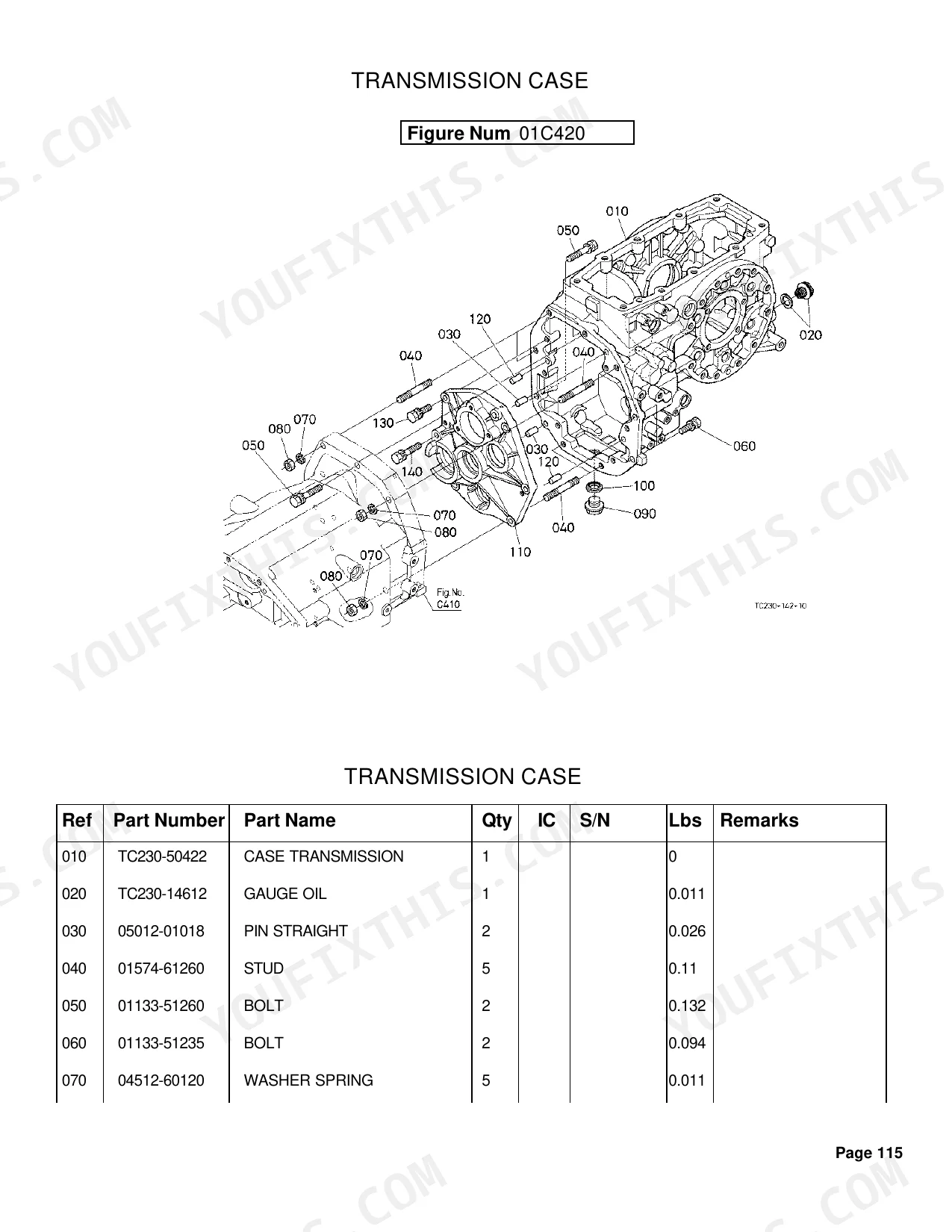
| Clutch & Transmission | Clutch, Clutch Lever, Clutch Pedal, Clutch Housing, Mid Case, Transmission Case, Countershaft, Range Gear Shaft, PTO Countershaft, PTO Clutch, Range Gear Shift Fork, Differential Lock Shift Fork, Range Gear Shift Lever, PTO Clutch Control Lever, PTO Clutch Valve | |
| PTO | PTO Drive Shaft, PTO Shaft, PTO Hydraulic Oil Line, PTO Protector | |
| Rear Axle, Differential & Brakes | Rear Differential, Rear Axle LH, Rear Axle RH, Brake LH, Brake RH, Brake Rod 1, Brake Rod 2, Brake Pedal, Rear Wheel, Rear Wheel Weight | |
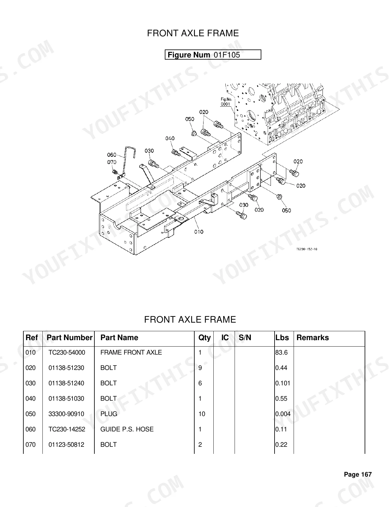
| Front Axle & Steering | Spiral Bevel Pinion, Front Wheel Drive Lever, Front Axle Frame, Propeller Shaft, Front Wheel Drive Shaft, Front Differential Case, Front Axle Case LH, Front Axle Case RH, Differential Gear Shaft, Front Axle, Steering Handle, Steering Controller, Steering Support, Tie Rod/Steering Cylinder, Steering Cylinder, Front Wheel | |
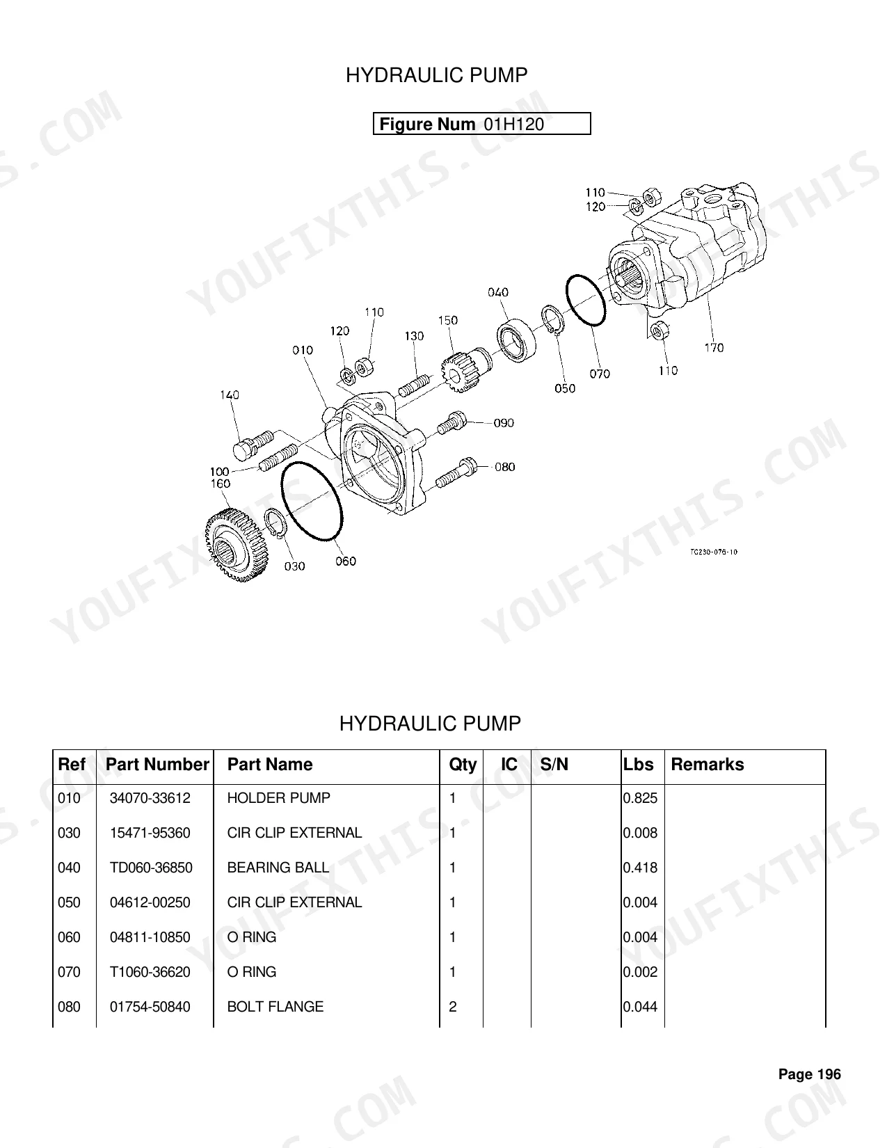
| Hydraulics & 3-Point Hitch | Hydraulic Pump, Hydraulic Oil Line, Hydraulic Outlet Block, Hydraulic Cylinder, Lift Arm, Feed Back Lever, Control Valve, Position Control Lever, Top Link, 3-Point Linkage 1, 3-Point Linkage 2, Drawbar, Draft Control Lever, Top Link Holder, Swinging Drawbar/Clevis Drawbar, Auxiliary Control Valve | |
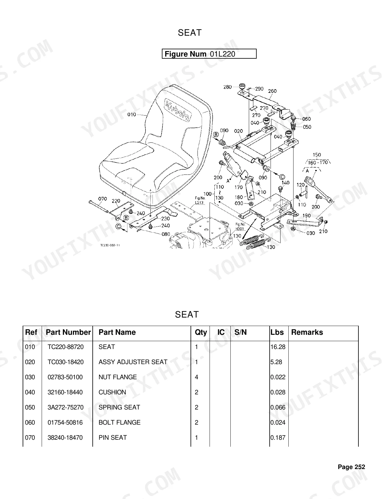
| Body & Operator Station | Head Cover, Cruise Control Cable, Front Grille, Hood Front Support, Hood, Hood Side, Hood Side Cover, Shutter Plate, Hood Rear, Fender, Fender Support, Floor Sheet Cover, Seat, Step, ROPS | |
| Decals & Accessories | Tool Box, Label 1, Label 2, Accessories and Service Parts | |
| Other Components | HST, Cruise Control Lever, Neutral Holder Link, Bevel Gear, Differential, Smv Emblem, Front Bumper, Front Weight |
Quick Reference Specifications
| Specification | Value | Page |
|---|---|---|
| Cylinder Head Gasket Thickness (Max) | 1.35mm | p. 8 |
| Piston Oversize Option | +0.25mm | p. 18 |
| Crankpin Undersize Option | -0.40mm/SET | p. 18 |
| Injection Pump Shim Thickness (Min) | 0.175mm | p. 28 |
| Nozzle Holder Washer Adjusting Thickness (Example) | 0.900mm | p. 35 |
| Battery Type | 80D26R | p. 74 |
| Headlight Bulb Wattage | 25W | p. 84 |
| Hazard Light Bulb Wattage | 23W | p. 86 |
| Rear Lamp Bulb Wattage (Dual Filament) | 23/8W | p. 87 |
| Fuse Rating (Example) | 5A | p. 89 |
| HST Servo Regulator Shim Thickness (Max) | 0.5mm | p. 107 |
| HST Input Gear Teeth Count | 23T | p. 112 |
Kubota L4400H Common Problems This Manual Covers
Kubota L4400H starter clicks or cranks slowly with good battery voltage in cold weather
Pull up the battery diagram on page 74 for the exact terminal and cord arrangement. Before buying replacements, confirm your machine takes the 80D26R battery. Corroded connections usually trace to the cords, support brackets, or retainers, all listed there by part number.
Manual Section: Battery p. 74Hydrostatic transmission does not move tractor, slips, or responds weakly under heavy load
Open the HST relief valve exploded view on page 106, where the shim part numbers live. Pick the right shims and keep the servo regulator shim at or below its 0.5mm maximum. The same view lists the O-rings and plugs behind internal hydrostatic pressure leaks.
Manual Section: HST (Relief Valve) [Component Parts] p. 106Engine loses power under load or stalls when engaging work implements after high hours
Trace the piston kits through the engine parts diagram on page 18. Note the +0.25mm oversize option for worn cylinders as you pull the numbers for rings and pins. Connecting rod assemblies vary by engine block production run, so match yours exactly.
Manual Section: Piston and Crankshaft p. 18Engine cranks but will not start or dies shortly after starting due to weak fuel supply
Find the correct replacement assembly in the injection pump breakout on page 27. Mind the shim part numbers, since minimum thickness runs 0.175mm. Fuel tube and jet start cock numbers sit in that same exploded view.
Manual Section: Injection Pump p. 27Front headlights fail to illuminate or flicker intermittently during evening mowing operations
Look up the bulb and wire harness part numbers in the headlight exploded view on page 84. Order the 25W headlight bulb specified for this model. The lamp unit and cord clamp parts are cataloged there too, for replacing damaged front sections.
Manual Section: Head Light p. 84Frequently Asked Questions
What are the replacement specifications for Fuel filter?
The fuel filter element carries part number 1A001-43160 and weighs 0.165 lbs. You'll find it under the 'FUEL FILTER [COMPONENT PARTS]' section of the catalog. p. 60
What are the replacement specifications for Air filter?
The air filter uses two elements: an outer, part number TA040-93230 at 1.232 lbs, and an inner, part number TA040-93220 at 0.429 lbs. Both appear in the 'AIR CLEANER' section. p. 47
How will I receive this Kubota L4400H Parts Catalog?
A 312-page Parts Catalog in searchable PDF, ready the moment your checkout clears. Read it on a computer, tablet, or phone, with no shipping wait.
Are there any print restrictions on this manual?
No restrictions at all. Print individual pages, full chapters, or the entire manual. The PDF is completely unlocked.


Reviews
There are no reviews yet.