


Part of the Kubota Parts Manuals.
Finding the exact part number before a counter trip or a wrong-part return is what these 310 pages are built around. Engine coverage spans exploded views, crankcase through governor. Drivetrain covers the HST unit, all seven transmission shafts, the rear differential, and three rear wheel size variations. Chassis work runs from front axle frame to ROPS. On the hydraulic side you'll find gear pump component breakdowns, pipe routing for the PS, suction, delivery, return, and charge circuits, and control valve internals across three valve assemblies. Specs sit right where you order: piston oversize at +0.5MM, crankpin metal undersize at -0.2MM. System bookmarks and full-text search let you pull a part name or number on any device and order it right the first time.
What's Inside This Kubota B2150HSD Parts Manual
| System | Pages | Key Topics |
|---|---|---|
| Fuel System | Nozzle Holder, Fuel Camshaft, Injection Pump, Engine Stop Lever, Speed Control Plate, Governor, Air Cleaner, Engine Stop Rod, Accelerator Lever, Fuel Tank, Fuel Pipe 1, Fuel Filter, Fuel Pipe 2, Speed Control Pedal | |
| Cooling System | Water Pump, Water Flange/Thermostat, Fan, Water Pipe, Radiator | |
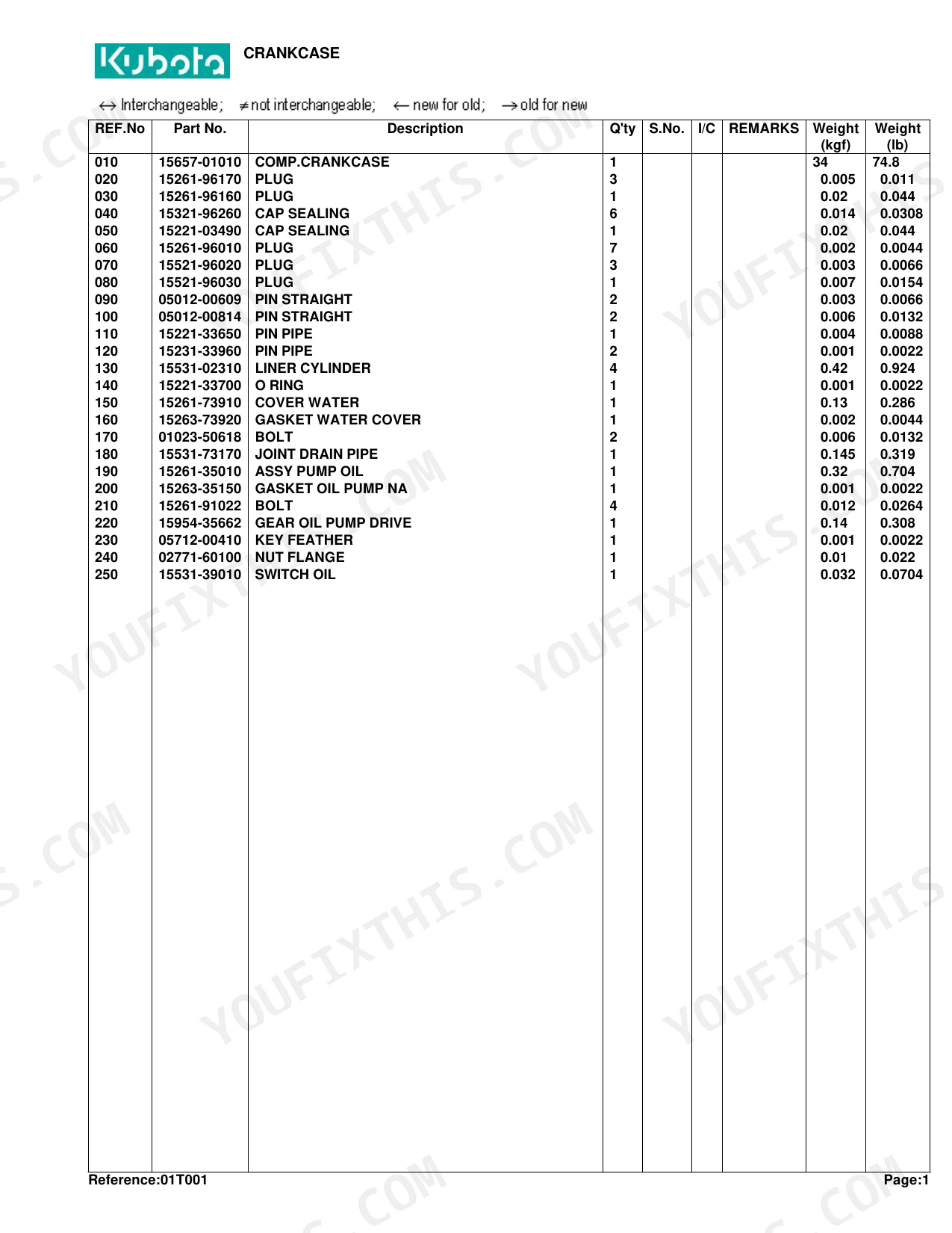
| Engine | Crankcase, Oil Pan, Piston/Crankshaft, Main Bearing Case, Flywheel, Cylinder Head, Valve/Rocker Arm, Cylinder Head Cover, Inlet Manifold, Exhaust Manifold, Camshaft, Gear Case, Upper Gasket Kit, Lower Gasket Kit, Muffler, Bevel Gear Case | |
| Electrical System | Dynamo, Alternator, Starter, Battery, Light, Working Light, Panel/Switch, Panel Board, Wire Harness | |
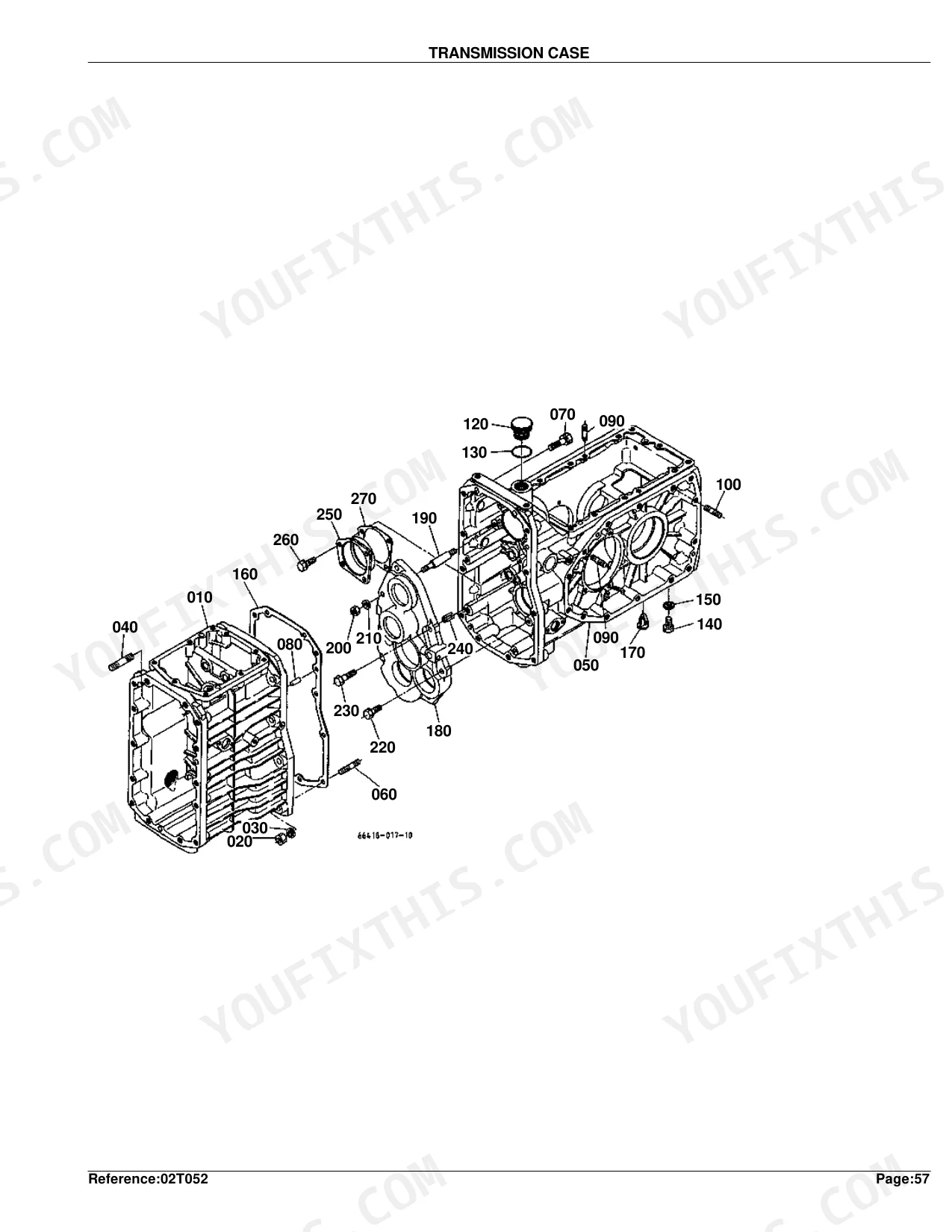
| Clutch & Transmission | Clutch, Clutch Rod, Clutch Pedal, Clutch Housing, Transmission Case, Transmission Case Cover, Range Gear Shift Lever, Range Gear Shift Fork, Clutch Disk, Shift Lever | |
| PTO | PTO Shaft, Mid PTO, Front PTO, Front Wheel Drive Lever/PTO Lever, PTO Fork Shaft | |
| Rear Axle, Differential & Brakes | Rear Differential, Rear Axle, Rear Axle Case, Rear Wheel, Brake, Brake Rod, Brake Pedal, Brake Interlocker | |
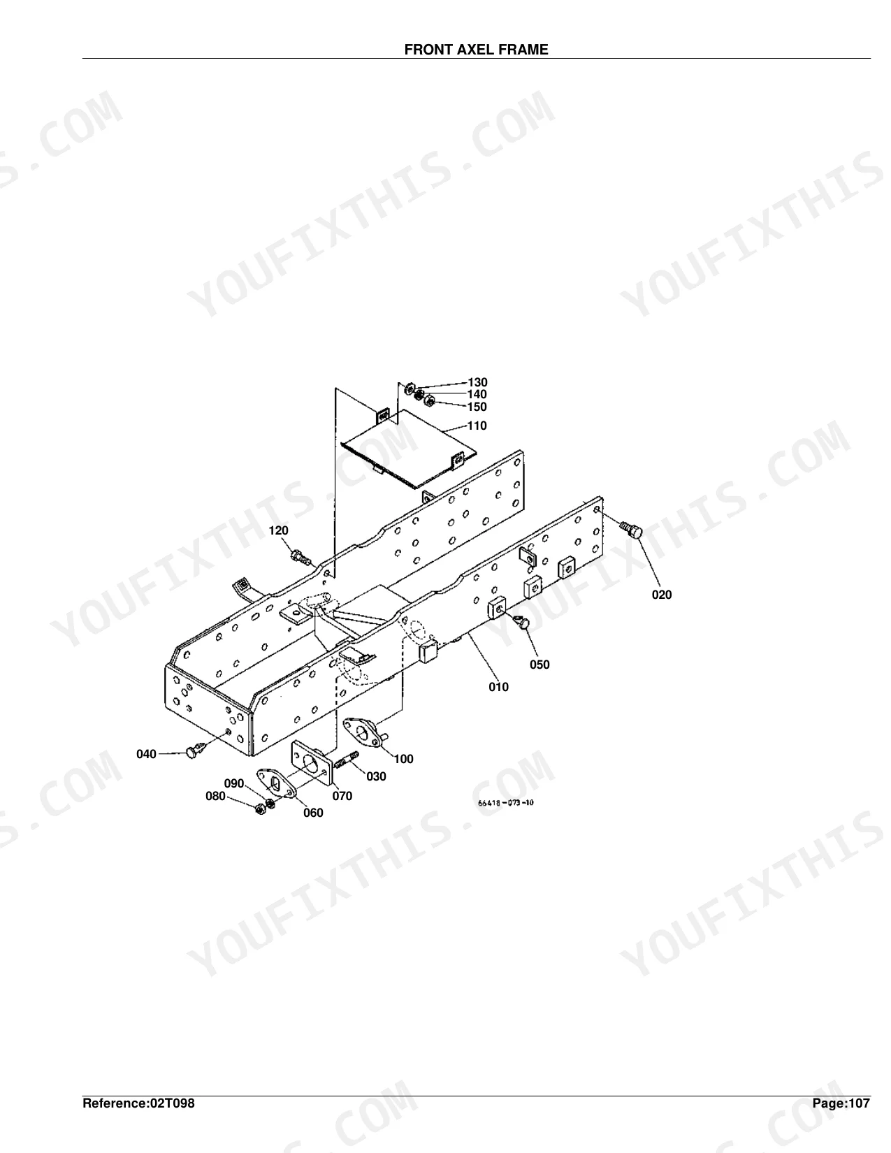
| Front Axle & Steering | Propeller Shaft, Front Axle Case, Front Axle Arm, Front Differential, Front Wheel, Front Axle Frame, Manual Steering, Power Steering | |
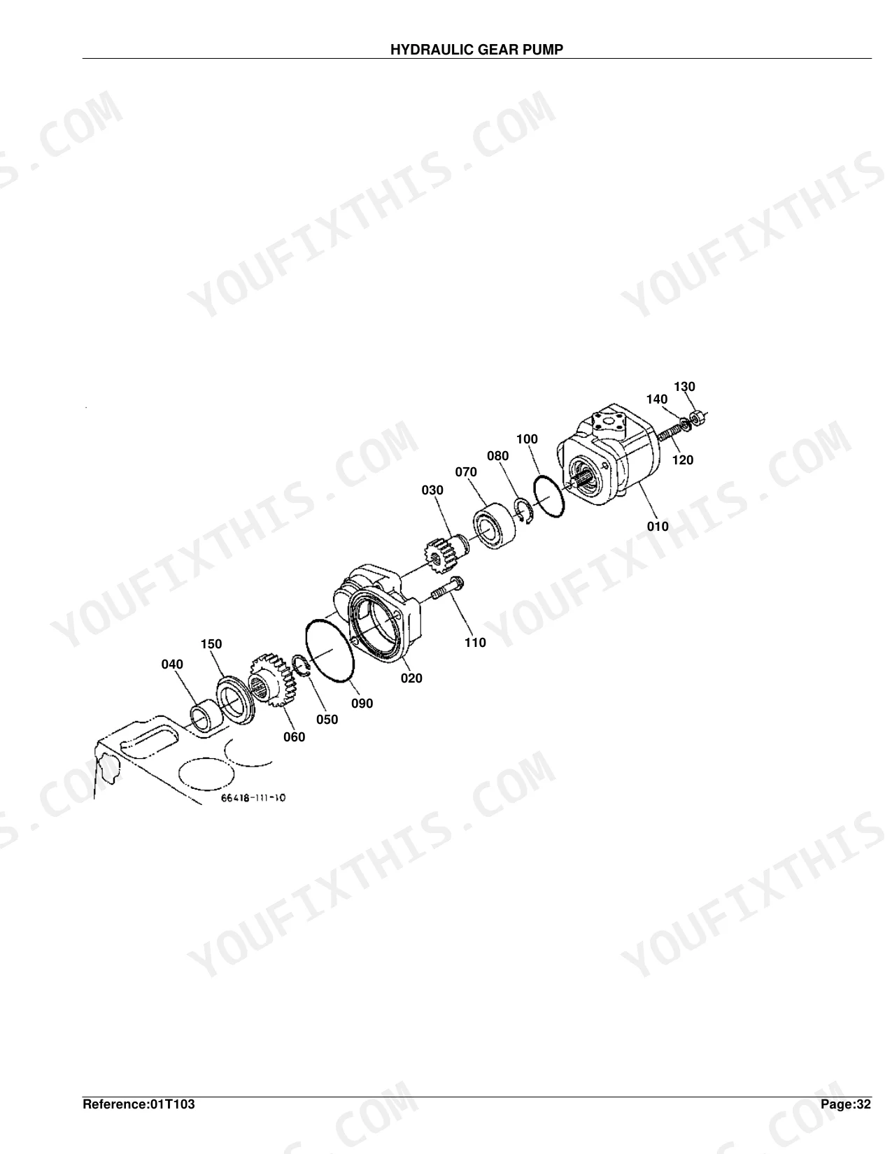
| Hydraulics & 3-Point Hitch | Hydraulic Gear Pump, Hydraulic Pipe, Hydraulic Block, Lift Arm, Hyd.Cylinder Cap, Control Valve, Control Valve1, Control Valve2, Control Valve3, Top Link, Lower Link/Lift Rod, Drawbar | |
| Body & Operator Station | Front Weight Bracket, Hood, Hood Cover Rear, Hood Front, Hood Side, Dust Cover, Hood Support, Fender, Seat, Step, ROPS | |
| Decals & Accessories | Label 1, Label 2, Accessories and Service Parts | |
| Other Components | Tension Pulley, HST, 1st Shaft/2nd Shaft, 3rd Shaft, 4th Shaft, Front Drive Shaft/6th Shaft, 7th Shaft, Neutral Holder, Speed Change Plate, Shift Set Lever, Bi-Speed Turn Lever, Front Drive Fork, Diff.Lock Pedal, Bevel Gear Shaft, Bi-Speed Turn Case, Front Drive Shaft |
Quick Reference Specifications
| Specification | Value | Page |
|---|---|---|
| Fuse Rating | 15A | p. 115 |
| Piston Oversize | +0.5MM | p. 11 |
| Crankpin Metal Undersize | -0.2MM | p. 11 |
| Nozzle Adjusting Washer Thickness (Min) | 1.00MM | p. 24 |
| Nozzle Adjusting Washer Thickness (Max) | 1.95MM | p. 24 |
| Fuse Auto Rating | 15A | p. 115 |
| Transmission Case Shim Thickness | 0.2MM | p. 125 |
| 1st Shaft Tooth Count | 13T | p. 137 |
| Rear Bevel Gear Ratio | 6-37T | p. 175 |
| Front Bevel Gear Ratio | 7-34T | p. 211 |
| Bi-Speed Turn Clutch Gear Tooth Count | 17T | p. 215 |
Kubota B2150HSD Common Problems This Manual Covers
Intermittent crank condition needing replacement fuses or safety interlock switches
Pull the wire harness layout from the parts diagram on page 114. The main electrical components are laid out there; verify part numbers for the 15A auto-rating fuses on page 115, then order the matching safety switches from the component list to restore the starting circuit.
Manual Section: Wire Harness [A][Au][Nz] p. 114Loss of drive or weak hydrostatic transmission response needing replacement filters and internal seals
Trace the hydrostatic transmission components on the drivetrain parts diagram, page 124. Find the part numbers for the transmission case cover and its internal pieces, and confirm the correct 0.2MM transmission case shim on page 125 before swapping the worn parts.
Manual Section: Transmission Case p. 124Complete engine rebuild required after severe lower end knock and poor cylinder compression
Match your engine serial number against the parts number list on page 7, then work the block components from the engine parts diagram on page 6. For internal pieces, the +0.5MM oversize piston carries its own part number on page 11.
Manual Section: Crankcase p. 6Grinding noise from the front differential during tight turns while operating in four wheel drive
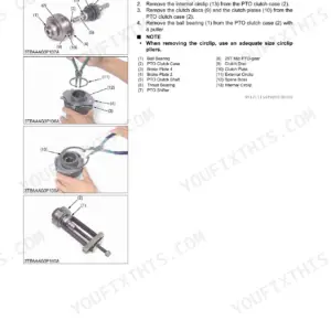
Open the exploded view of the bi-speed turn clutch on page 214 and pick the right clutch disk and hardware from the parts list. The 17T bi-speed turn clutch gear has its part number on page 215; confirm it before ordering.
Manual Section: Clutch Disk [With Bi-Speed Turn] p. 214Frequently Asked Questions
What are the replacement specifications for fuses?
Part No. 35820-75560 is the replacement fuse, listed as "FUSE AUTO" with a 15A rating. The wire harness assembly uses two of them. p. 115
What part numbers are needed for hydrostatic transmission repair on the B2150HSD?
The drivetrain parts diagram on page 124 lists the transmission case cover and internal components. The correct transmission case shim is 0.2MM; confirm the part number on page 125 before ordering. p. 124
How do I find the right oversize piston part number for an engine rebuild?
Match your engine serial number on pages 6-7, then locate the +0.5MM oversize piston on page 11 of the engine parts diagram. Each oversize grade carries its own OEM part number. p. 6
Are exploded parts diagrams included for the hydraulic and drivetrain systems?
Yes. This parts catalog includes exploded parts diagrams with OEM part numbers for the hydraulic circuits, gear pump, control valves, and drivetrain including the bi-speed turn clutch disk and 17T gear on pages 214-215. p. 214


Reviews
There are no reviews yet.