

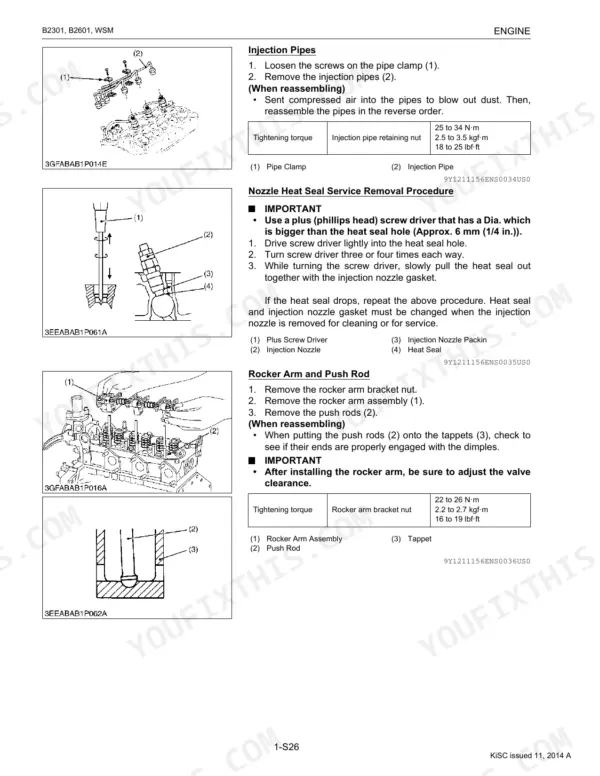
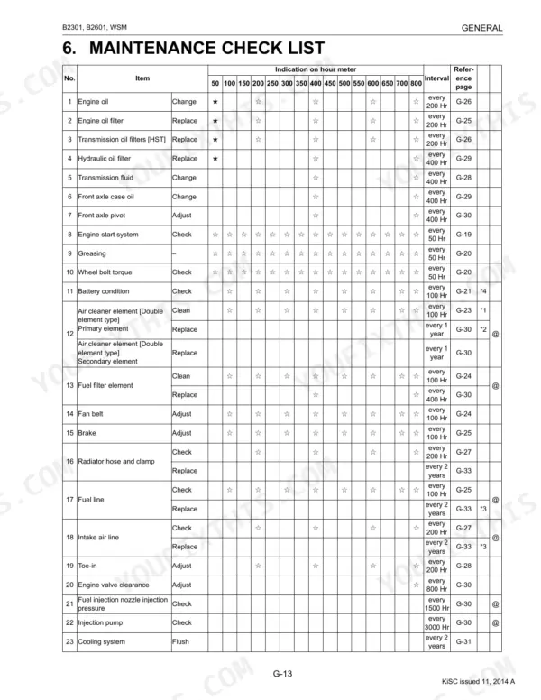


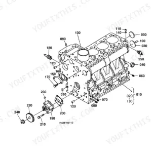
This is the Kubota workshop (shop) manual for the B2301 and B2601 tractors, publication 9Y111-11560, covering machines powered by the D1005-E4-D32 and D1105-E4-D32 diesel engines. Its 341 pages are written for the person doing the repair, with mechanism descriptions, checking and adjusting procedures, disassembly and assembly steps, and full servicing specifications.
The manual is organized into Information, General, Engine, Transmission, Rear Axle, Brakes, Front Axle, Steering, Hydraulic System, and Electrical System sections. You get tightening torques, valve clearances, charge pressures, wiring diagrams, troubleshooting charts, and the special tools Kubota specifies for each job.
Whether you are rebuilding the hydrostatic transmission, tracing a no-start on the electrical circuit, or setting brake free travel, this PDF gives you the factory service data and step-by-step procedures behind the work.
What's Inside This Manual
| System | Pages | Key Topics |
|---|---|---|
| G General | Tractor Identification, Handling Precautions for Electrical Parts and Wiring (Battery, Fuse, Connector, Handling of Circuit Tester, Color of Wiring), Lubricants, Fuel and Coolant | |
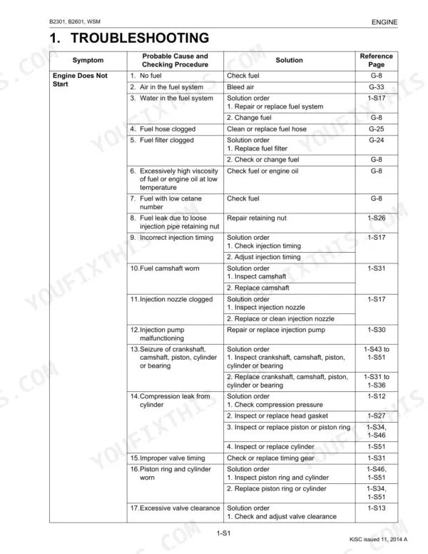
| Engine | Engine Body (Closed Breather, Governor), Checking, Disassembling and Servicing (Checking and Adjusting, Preparation, Disassembling and Assembling), Servicing Specifications | |
| Transmission | Front Case, Hydrostatic Transmission (Structure, Pump and Motor, Oil Flow and Valves, Control Linkage), Speed Set Device (Speed Set Linkage), Range Gear Shift Section | |
| Rear Axle | Diassembling and Servicing (Diassembling and Assembling), Structure | |
| Brakes | Linkage, Operation, Checking, Disassembling and Servicing (Checking and Adjusting, Disassembling and Assembling), Servicing Specifications | |
| Front Axle | Structure (Wheel Drive Model), Checking, Disassembling and Servicing (Checking and Adjusting, Disassembling and Assembling), Servicing Specifications | |
| Steering | Steering Controller, Steering Cylinder, Hydraulic Circuit, Hydraulic Pump, Checking, Disassembling and Servicing, Servicing Specifications | |
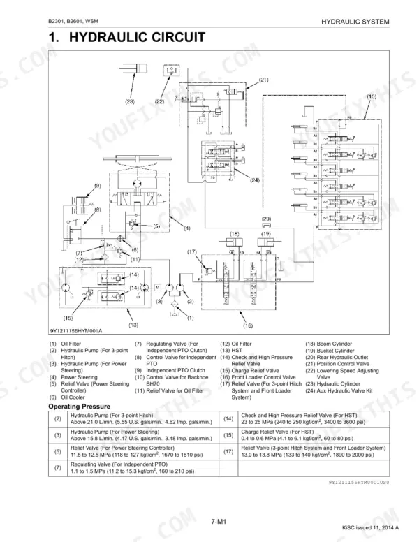
| Hydraulic System | Front Loader Control Valve (Structure, Operation), Remote Control Valve, Hydraulic Outlet, Hydraulic Circuit, Hydraulic Pump, Checking | |
| Electrical System | Wiring Diagram, Engine Starting System and Stopping System (Opc System Circuit, Controller, Safety Switch, Starter, Engine Stop Solenoid, Glow Plug), Charging System |
Every system also includes tightening torques, and troubleshooting.
Documents This Manual Refers To
The manufacturer cites these publications by number. We carry them:
Quick Reference Specifications
| Specification | Value | Page |
|---|---|---|
| All Models | ||
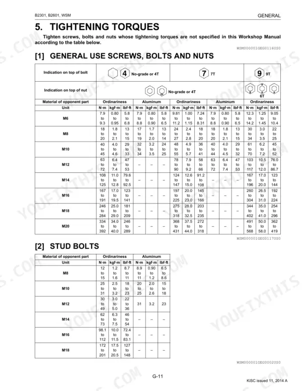
| Rear wheel mounting nut Tightening torque | 145 to 150 N·m | p. 35 |
| Front loader valve pipe joint bolt Tightening torque | 48 to 70 N·m | p. 163 |
| Fuel filter element Replacement Interval | every 400 Hr | p. 28 |
| Air cleaner element [Primary element] Replacement Interval | every 1 year | p. 28 |
| Hydraulic oil filter Replacement Interval | every 400 Hr | p. 28 |
| Fuel line Replacement Interval | every 2 years | p. 28 |
| Battery terminal Greasing Type | Multipurpose type grease NLGI-2 or NLGI-1 (GC-LB) | p. 23 |
| Fan belt tension | A deflection of between 7.0 to 9.0 mm | p. 39 |
| Brake Pedal Free Travel | 30 to 40 mm | p. 216 |
| Charge pressure | 0.4 to 0.6 MPa | p. 164 |
| B2301 | ||
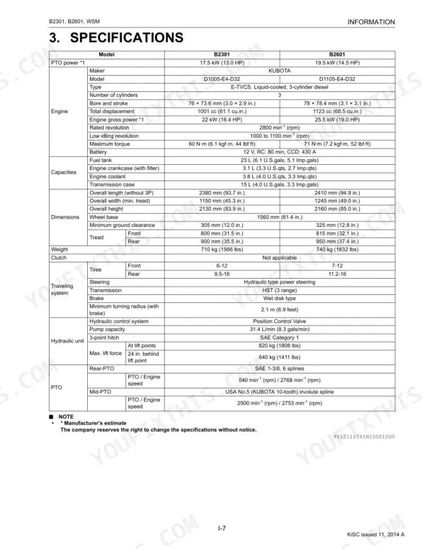
| PTO Power, B2301 | 17.5 kW (13.0 HP) | p. 11 |
| B2601 | ||
| PTO Power, B2601 | 19.5 kW (14.5 HP) | p. 11 |
