
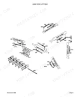
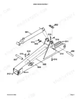
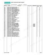
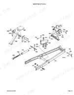
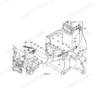
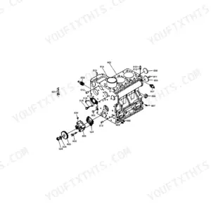
This Kubota B/L4520B, L4530B Parts Catalog (OEM #100K0595) stays narrow on purpose: 50 pages devoted to one backhoe attachment, with every exploded view, part number, and cross-reference set up so the right component ships the first time. Twenty-four pages of parts lists cover the main frame, boom assemblies for both the 4520B and 4530B, the dipperstick and bucket, hoses and fittings, tank and pump, three gear pump variants (4520B, 4530B Cessna, and 4530B Fenner-Stone), console valve, swing cylinder, stabilizer and boom cylinders, plus six mounting kits (B-4521 through L-4531). Hydraulic callouts note the 2x10-inch stabilizer cylinder on the 4520B against the 2x14.5-inch unit on the 4530B, and the 2.5x16.75-inch boom cylinder. Need the gear pump capscrew spec? It reads 33-38 N-m (25-28 ft-lbs). Pull it up on a tablet, find the part number, and skip the guesswork at the counter.
What's Inside This Kubota BL4520B, L4530B Parts Manual
| System | Pages |
|---|---|
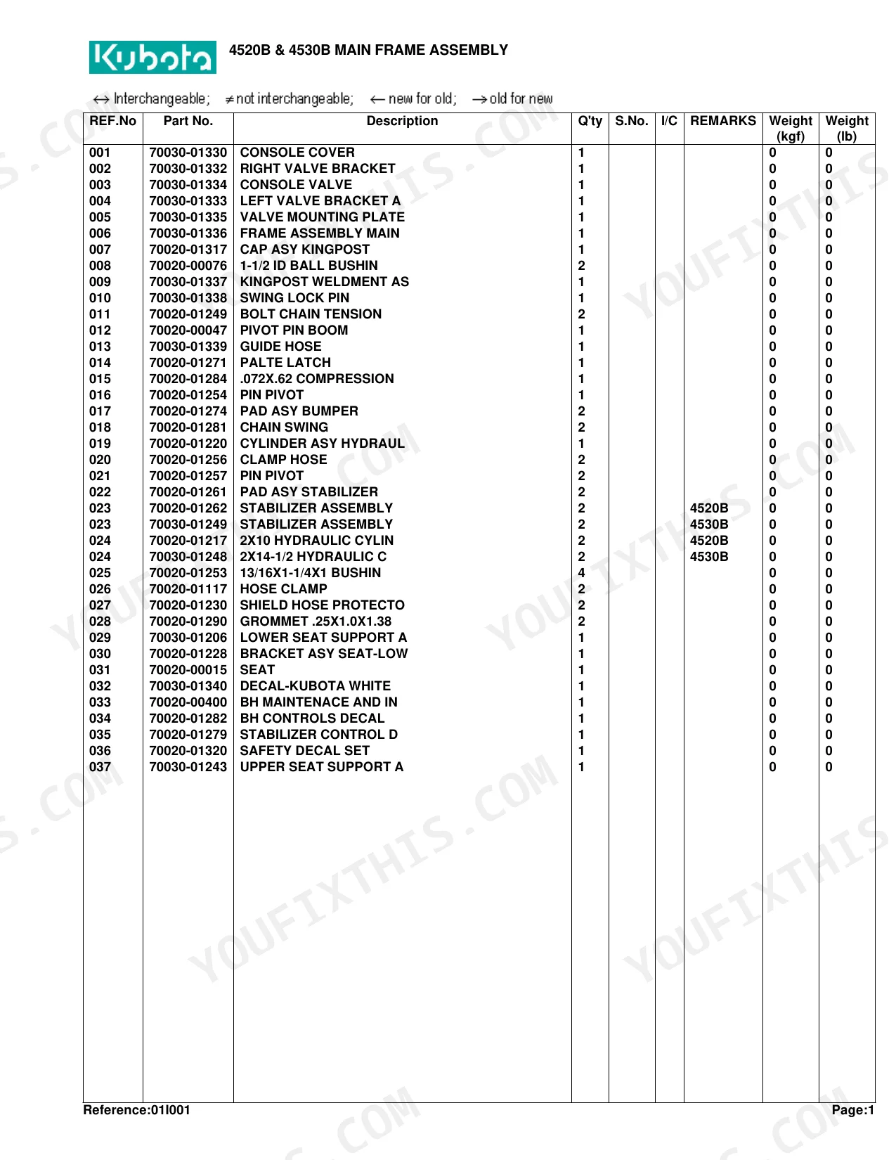
| 4520B & 4530B Main Frame Assembly | 3-4 |
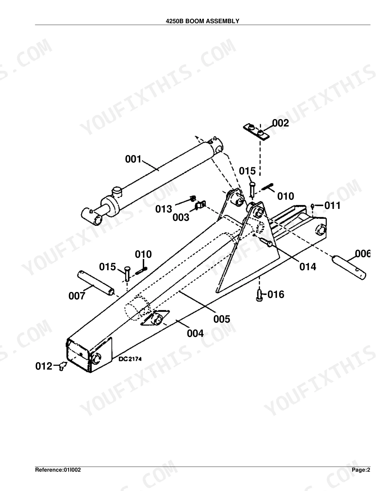
| 4250B Boom Assembly | 5-6 |
| 4530B Boom Assembly | 7-8 |
| 4520B & 4530B Dipperstick & Bucket Assembly | 9-10 |
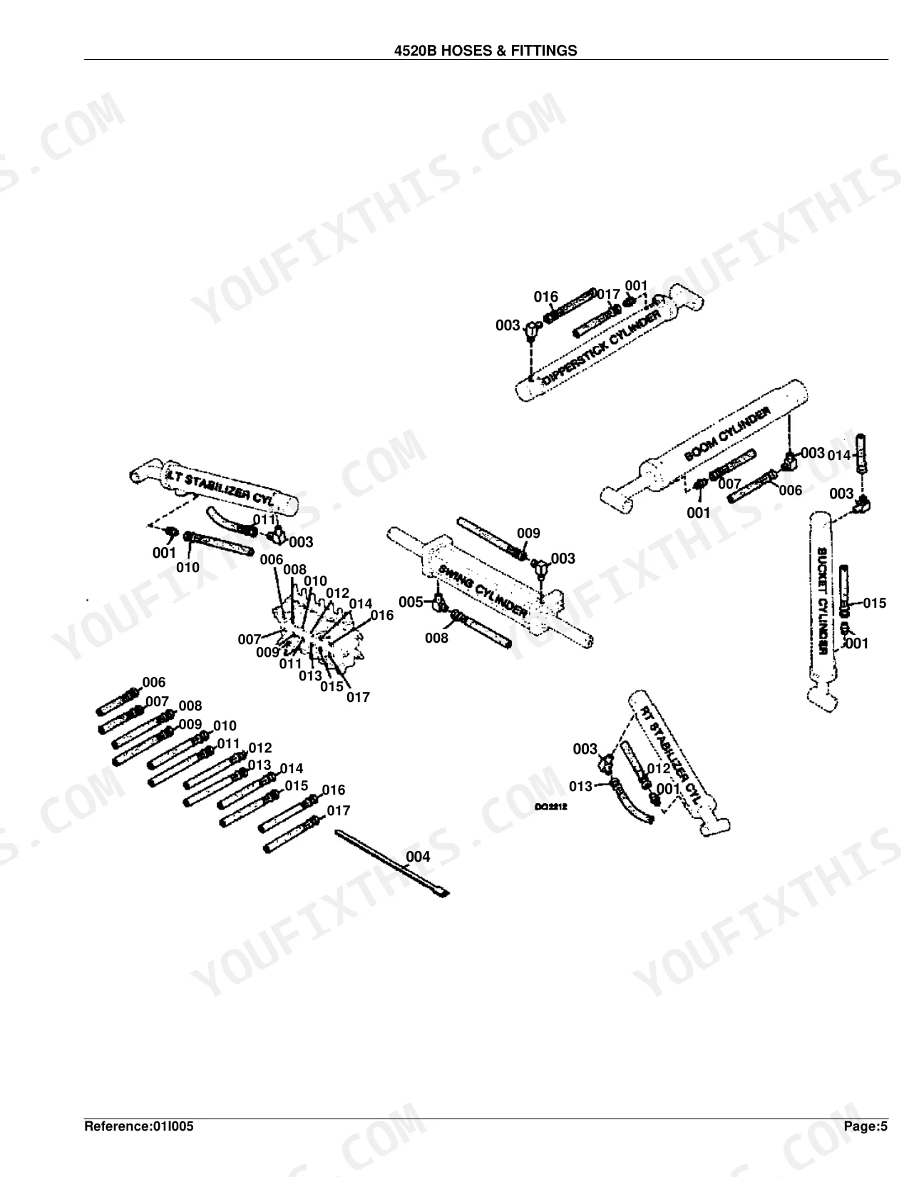
| 4520B Hoses & Fittings | 11-12 |
| 4530B Hoses & Fittings | 13-14 |
| 4520B Tank & Pump Assembly | 15-16 |
| 4530B Tank & Pump Assembly | 17-18 |
| 4520B Gear Pump Assembly | 19-20 |
| 4530B Cessna Gear Pump Assembly | 21-22 |
| 4530B Fenner-Stone Hydraulic Gear Pump Assembly | 23-24 |
| 4520B & 4530B Console Valve Assembly | 25-26 |
| 4520B & 4530B Valve Controls & Hardware | 27-28 |
| 4520B & 4530B Swing Cylinder | 29-30 |
| 4520B Dipperstick & Bucket Cylinder 4530B Bucket Cylinder | 31-32 |
| 4520B Stabilizer Cylinder | 33-34 |
| 4530B Stabilizer Cylinder | 35-36 |
| 4520B Boom Cylinder 4530B Boom & Dipperstick Cylinder | 37-38 |
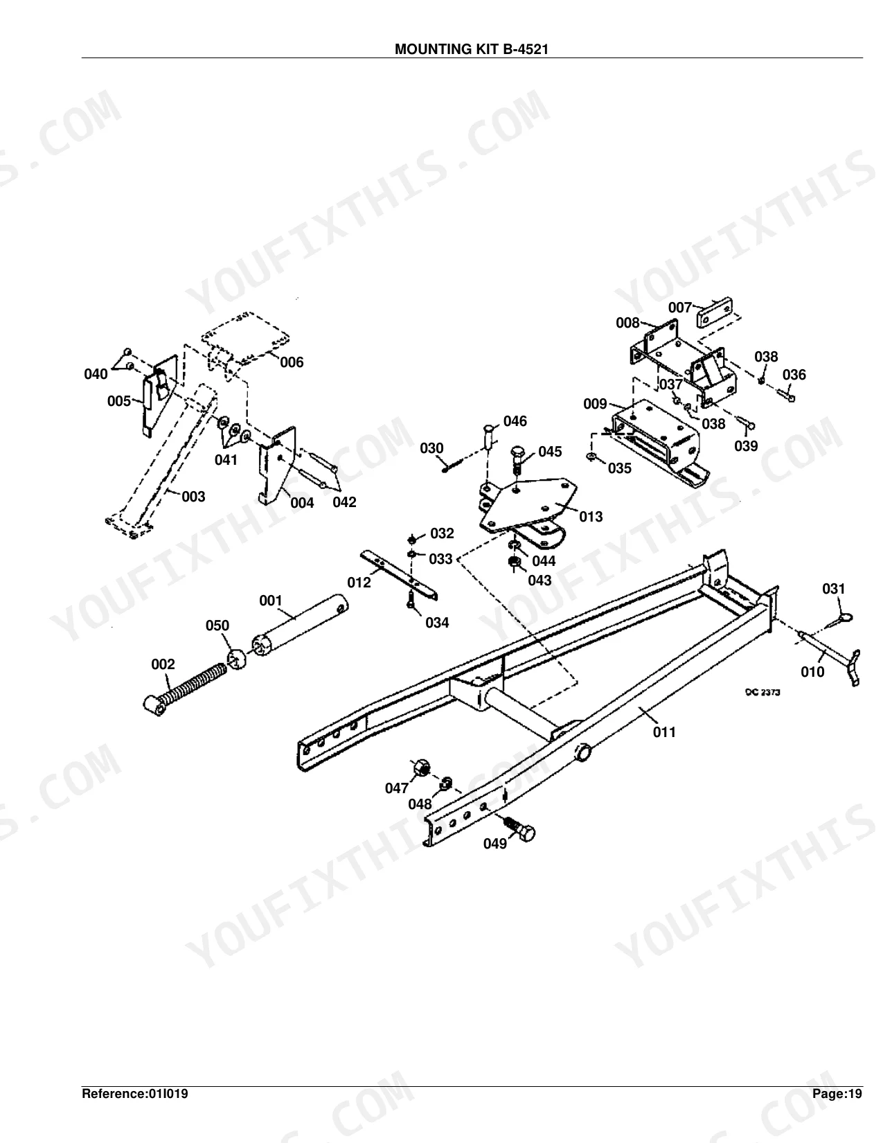
| Mounting Kit B-4521 | 39-40 |
| Mounting Kit L-4523 | 41-42 |
| Mounting Kit B-4524 | 43-44 |
| Mounting Kit L-4525 | 45-46 |
| Mounting Kit B-4526 | 47-48 |
| Mounting Kit L-4531 | 49-50 |
Quick Reference Specifications
| Specification | Value | Page |
|---|---|---|
| 4520B GEAR PUMP ASSEMBLY | ||
| Torque for (8) capscrews | 33-38 N-M/25-28 Ft. Lbs. | p. 19 |
| All Models | ||
| Ball Bushing ID | 1.5 inches | p. 4 |
| Pitch (Console Valve) | 8mm x 1.25mm | p. 26 |
| Tie Rod (Swing Cylinder) | 7/16 NF x 16 | p. 30 |
| Hydraulic Cylinder (Dipperstick/Bucket) | 2 x 16.75 inches | p. 32 |
| 4520B | ||
| Hydraulic Cylinder (Stabilizer) | 2x10 inches | p. 4 |
| Capscrew Torque (Gear Pump) | 33-38 N-M / 25-28 Ft. Lbs. | p. 19 |
| 4530B | ||
| Hydraulic Cylinder (Stabilizer) | 2x14.5 inches | p. 4 |
| Key Dimension (Cessna Gear Pump) | 1/4 x 1/4 x 15/16 inches | p. 22 |
| 4250B | ||
| Hydraulic Cylinder (Boom) | 2.5x16.75 inches | p. 6 |
| B/L4527B | ||
| Bucket Size (Standard) | 10 BH | p. 10 |
| L-4523 | ||
| Lock Pin (Mounting Kit) | 3/4 x 11 inches | p. 42 |
Kubota BL4520B, L4530B Common Problems This Manual Covers
Kubota B/L4520B backhoe hydraulic cylinder seal kit part number hard to identify p. 31
Check the exploded view on page 31. The dipperstick and bucket cylinder measures 2 x 16.75 inches and its seal kit part number appears in the parts list on page 32. For the boom cylinder, turn to page 37. Verify your serial number range before ordering to confirm compatibility.
Manual Section: 4520B Dipperstick & Bucket Cylinder 4530B Bucket CylinderOne joystick side unresponsive, need correct section seal repair kit part number p. 25
Open the Console Valve Assembly exploded view on page 25. Locate the Section Seal Repair Kit in the parts list on page 26. The console valve uses 8mm x 1.25mm thread pitch hardware. Cross-reference the complete valve and individual spool position control parts to identify which circuit's seals need replacement.
Manual Section: 4520B & 4530B Console Valve AssemblyGear pump assembly part numbers differ by variant, unsure which exploded view applies p. 19
Identify your pump manufacturer before ordering. The 4520B gear pump is on page 19, with capscrews torqued to 33-38 N·m (25-28 ft. lbs.). The 4530B has two variants: Cessna on page 21 and Fenner-Stone on page 23. Match your pump housing to the correct exploded view before pulling part numbers.
Manual Section: 4520B Gear Pump AssemblyStabilizer cylinder replacement parts unclear, bore and stroke dimensions don't match available listings p. 33
Verify your model before pulling parts. The 4520B stabilizer cylinder measures 2 x 10 inches; find its parts list on page 33. The 4530B runs a larger 2 x 14.5-inch cylinder; its exploded view starts on page 35. The collar and cylinder assembly part numbers differ between models, so confirm the listing before ordering.
Manual Section: 4520B Stabilizer CylinderHydraulic hose and fitting part numbers unclear, connectors look identical between models p. 11
Pull the correct hoses diagram for your machine. The 4520B hoses and fittings layout starts on page 11; the 4530B version is on page 13. Both include 9/16-18 x 1/4 NPTF 90-degree connectors, but the 4530B adds a 9/16 x 1/4 male restrictor fitting not listed for the 4520B. Verify the part number before ordering.
Manual Section: 4520B Hoses & FittingsSwing cylinder tie rod part number needed, hardware looks interchangeable with boom cylinder hardware p. 29
Go to the Swing Cylinder exploded view on page 29. The tie rod for both models is 7/16 NF x 16; verify this against the parts list on page 30 before sourcing hardware. Do not substitute boom cylinder tie rod hardware. The full hydraulic swing cylinder assembly number is also listed on page 29.
Manual Section: 4520B & 4530B Swing CylinderFrequently Asked Questions
How quickly can I access this Kubota B/L4520B, L4530B manual after buying?
A 50-page Parts Catalog in searchable PDF, downloadable the moment checkout finishes. Open it on a computer, tablet, or phone. No shipping wait.
Can I print specific sections of this Kubota B/L4520B, L4530B Parts Catalog?
None at all. The PDF is DRM-free, so print whatever sections you need for the shop. Standard letter or A4 paper works fine.
Does this Kubota B/L4520B, L4530B manual include hydraulic schematics?
This is a parts catalog, so it shows exploded parts diagrams rather than circuit schematics. It includes detailed exploded views of the hydraulic components — pump, control valve, cylinder, and oil lines — with OEM part numbers, not wiring-style circuit diagrams.
Document Quality
This document is a scanned PDF with an optical character recognition (OCR) layer, allowing you to search and copy text from the part lists and instructional pages. The text throughout is crisp and easy to read. Diagrams and illustrations are clear scanned images with all labels readable, though they are raster-based and may pixelate if zoomed very closely. Pages are consistently clean with no significant scan artifacts, stains, or skewed content. There are no notable blank or filler pages present in this document.


Reviews
There are no reviews yet.