


Looking for the factory setup and operating procedures for your Kubota LA302 or LA402 front loader? This 36-page operator manual covers four models (LA272, LA302, LA352, and LA402), guiding you from tractor prep through daily maintenance. The guide includes 10 pages of step-by-step loader operation covering bucket fill, lift, carry, dump, float control, bank loading, and backfilling. A pre-operation checklist walks you through transmission fluid levels, tire inflation, rear ballast, and purging air from the hydraulic system. Performance charts provide lift capacity data and dimensional specs for all four models, alongside the complete install, removal, and storage sequence. Stop guessing at mounting hardware: front axle frame mounting bolts torque to 15.0 kgf·m (108 ft-lbs), and brace nuts require 18.0 kgf·m (130 ft-lbs). Download the searchable PDF, open it on your phone at the machine, and start work with the correct factory numbers.
What's Inside This Kubota LA272–LA402 Series Operator Manual
| System | Pages | Key Topics |
|---|---|---|
| Safe Operation | 7-10 | Read and Understand Manuals, ROPS and Seat Belt Use, Loader Operation Safety, Handling Loose or Shiftable Loads, Parking and Leaving Tractor, Loader Controls and Maintenance |
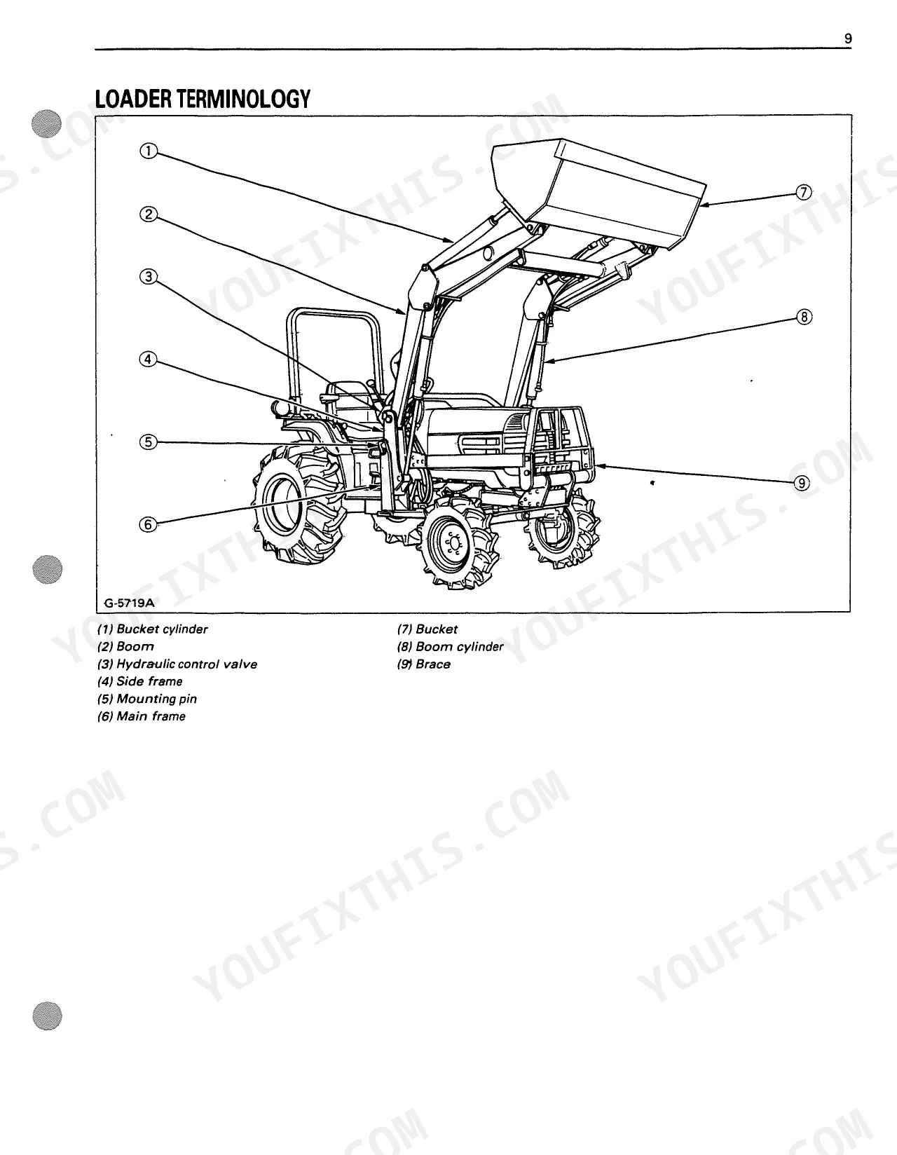
| Servicing of Loader | 11-22 | Specifications, Performance Chart, Loader Terminology, Setting-Up Instructions |
| Pre-Operation Check | 23-24 | Lubrication, Transmission Fluid, Rear Ballast, Tire Inflation, Test Operation, Removing Air From Hydraulic System |
| Operating the Loader | 25-29 | Filling The Bucket, Lifting The Load, Carrying The Load, Dumping The Bucket, Lowering The Bucket, Operating With Float Control, Loading From A Bank, Peeling And Scraping |
| Maintenance | 30-31 | Lubrication, Daily Checks (American Standard Cap Screws with UNC or UNF Threads, Metric Cap Screws) |
| Removing the Loader | 32 | Raise Boom and Stop Engine, Remove Spring Pins and Rotate Stands, Lower Boom and Raise Front Wheels, Release Hydraulic Pressure and Disconnect Hoses, Back Tractor Away |
| Storing the Loader | 33 | Store in Clean Dry Place, Ensure Proper Support, Attach Protective Plugs and Caps, Check Hydraulic Hoses and Connections, Lubricate Loader, Apply Grease to Cylinder Rods and Pins |
| Reinstalling the Loader | 34 | Drive Tractor Between Side Frames, Connect Hoses, Engage Side Frames with Main Frame, Reinstall Mounting Pins, Store Stands to Original Positions, Lower Boom and Level Bucket |
Quick Reference Specifications
| Specification | Value | Page |
|---|---|---|
| LA272, LA302, LA352, LA402 | ||
| Main frame (Clutch housing) bolts torque | 8.5 kgf·m (61 ft-lbs) | p. 22 |
| Main frame (Front axle frame) bolts torque | 15.0 kgf·m (108 ft-lbs) | p. 22 |
| Main frame (Center frame) bolts torque | 10.0 kgf·m (72 ft-lbs) | p. 22 |
| Main frame (Sub frame) nuts torque | 8.5 kgf·m (61 ft-lbs) | p. 22 |
| Brace nuts torque | 18.0 kgf·m (130 ft-lbs) | p. 22 |
| Side frame connector nuts torque | 15.0 kgf·m (108 ft-lbs) | p. 22 |
| LA402 | ||
| Main frame (Sub frame) bolts torque | 17.0 kgf·m (123 ft-lbs) | p. 22 |
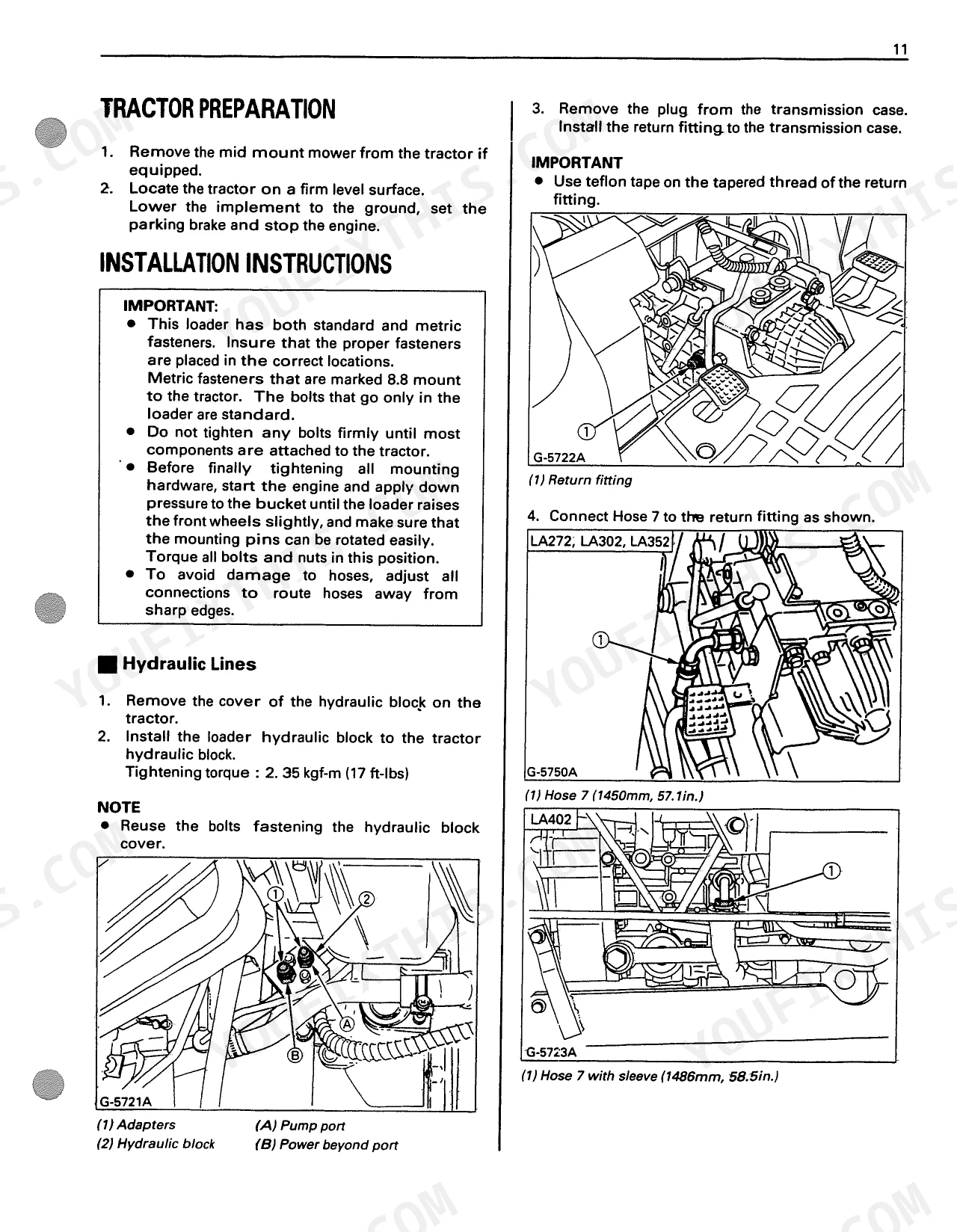
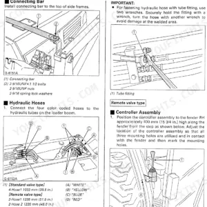
| Hose 7 length (with sleeve) | 1486 mm (58.5 in.) | p. 16 |
| All Models | ||
| Hydraulic leak troubleshooting | Visually check for hydraulic leaks and broken, missing, or malfunctioning parts. Make necessary repairs before operation. Inspect all hoses for cuts or wear and ensure all fittings are tight. Before disconnecting lines, relieve all hydraulic pressure. Do not use hands to search for suspected leaks; use cardboard or wood. If injured by escaping fluid, obtain medical treatment at once. | p. 30 |
| Mounting hardware torque guidance | Tighten all bolts and nuts in the following order to the required torque as specified in the 'Tightening Bolts and Nuts' table on page 22. Do not tighten any bolts firmly until most components are attached to the tractor. Before final tightening, apply down pressure to the bucket until the loader raises the front wheels slightly, and ensure mounting pins can be rotated easily. | p. 22 |
| Hydraulic block installation torque | 2.35 kgf·m (17 ft-lbs) | p. 17 |
| LA272, LA302, LA352 | ||
| Hose 7 length (without sleeve) | 1450 mm (57.1 in.) | p. 16 |
Kubota LA272–LA402 Series Common Problems This Manual Covers
Loader raises slowly, weakly, or hydraulic functions feel jerky during test operation p. 24
Purge trapped air from the hydraulic lines by following the test operation sequence detailed on page 24. Cycle the boom and bucket cylinders multiple times to remove air. Verify rear tire inflation is set to 140kPa (20psi) to maintain stability before operating. Never use hands to check for suspected leaks.
Manual Section: Hydraulic System Air RemovalVisible hydraulic oil dripping from hose fittings or valve block after startup p. 30
Relieve all hydraulic pressure according to the schedule on page 30 before touching lines. Inspect hoses for cuts or wear, using cardboard to check for pinhole leaks. If the valve block is leaking, torque the installation bolts to 2.35 kgf-m (17 ft-lbs) using the service procedures on page 17.
Manual Section: Hydraulic Leaks and Hose Damage CheckLA402 pivot mounts emit creaking or clunking noises when lifting a load p. 30
Inspect mounting hardware for looseness. Apply down pressure to the bucket until the front wheels raise slightly to check pin rotation. Torque the main frame clutch housing bolts to 8.5 kgf-m (61 ft-lbs) using the specifications on page 22. Lubricate all grease fittings every 10 hours as outlined on page 30.
Manual Section: Hardware Tightness CheckMounting pins are hard to align and side frames will not detach properly p. 34
Lower the boom and level the bucket on flat ground before driving the tractor slowly between the side frames. Connect the hydraulic hoses and verify the main frame front axle frame bolts are torqued to 15.0 kgf-m (108 ft-lbs). Reinstall the mounting pins carefully as shown on page 34.
Manual Section: Reinstalling the LoaderFrequently Asked Questions
What are the torque specs for Kubota LA272, LA302, LA352, LA402 loader bolts?
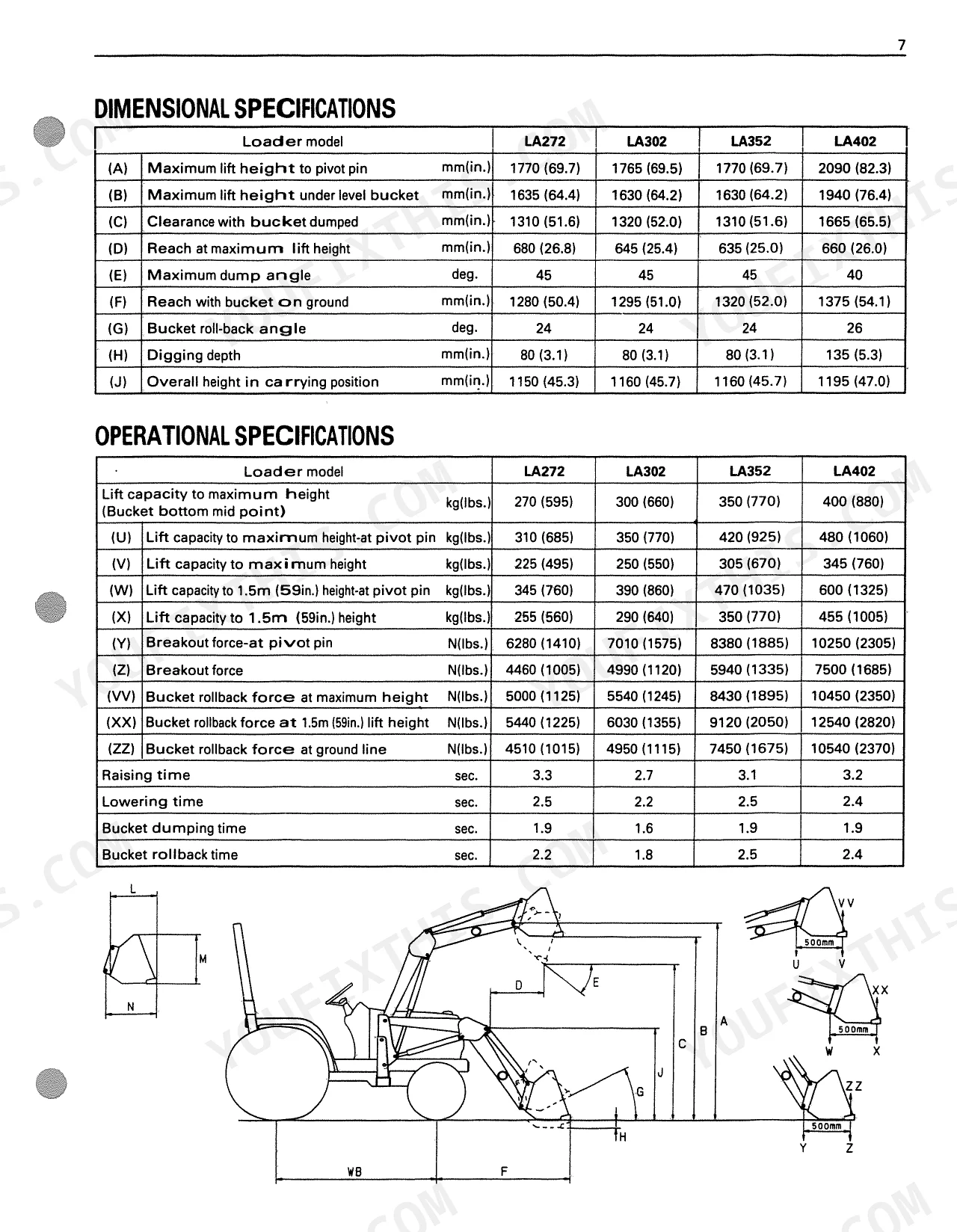
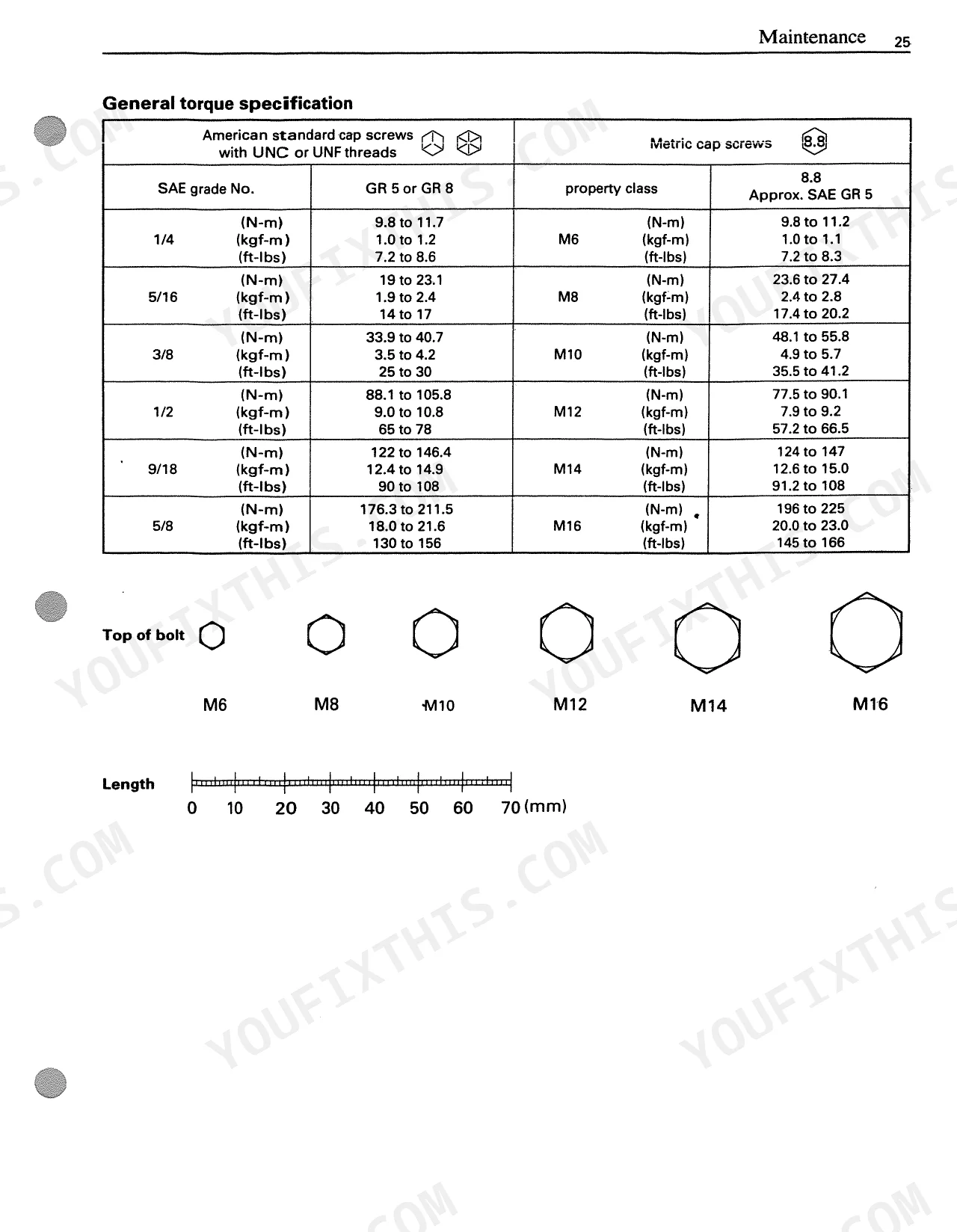
For the LA272, LA302, LA352, and LA402 loaders, specific torque values are provided for various bolts. For instance, Main frame (Clutch housing) bolts (6-M12) require 8.5 kgf·m (61 ft-lbs), Main frame (Front axle frame) bolts (4-M14 for LA272/LA302/LA352, 8-M14 for LA402) require 15.0 kgf·m (108 ft-lbs), and Brace nuts (14-9/16 for LA272/LA302/LA352, 20-9/16 for LA402) require 18.0 kgf·m (130 ft-lbs). A general torque specification chart for American standard and Metric cap screws is also available.
Document Quality
This document is a scanned PDF with an OCR layer, allowing you to search and copy the full text. The text is crisp and easy to read, with only minor scanning artifacts on some characters. All diagrams and illustrations are clear raster images, and their labels are readable. Pages are clean, free of stains or marks, though faint grey circles are present in the corners from the scanning process. Pages 2, 4, and 10 are intentionally blank.

Reviews
There are no reviews yet.