
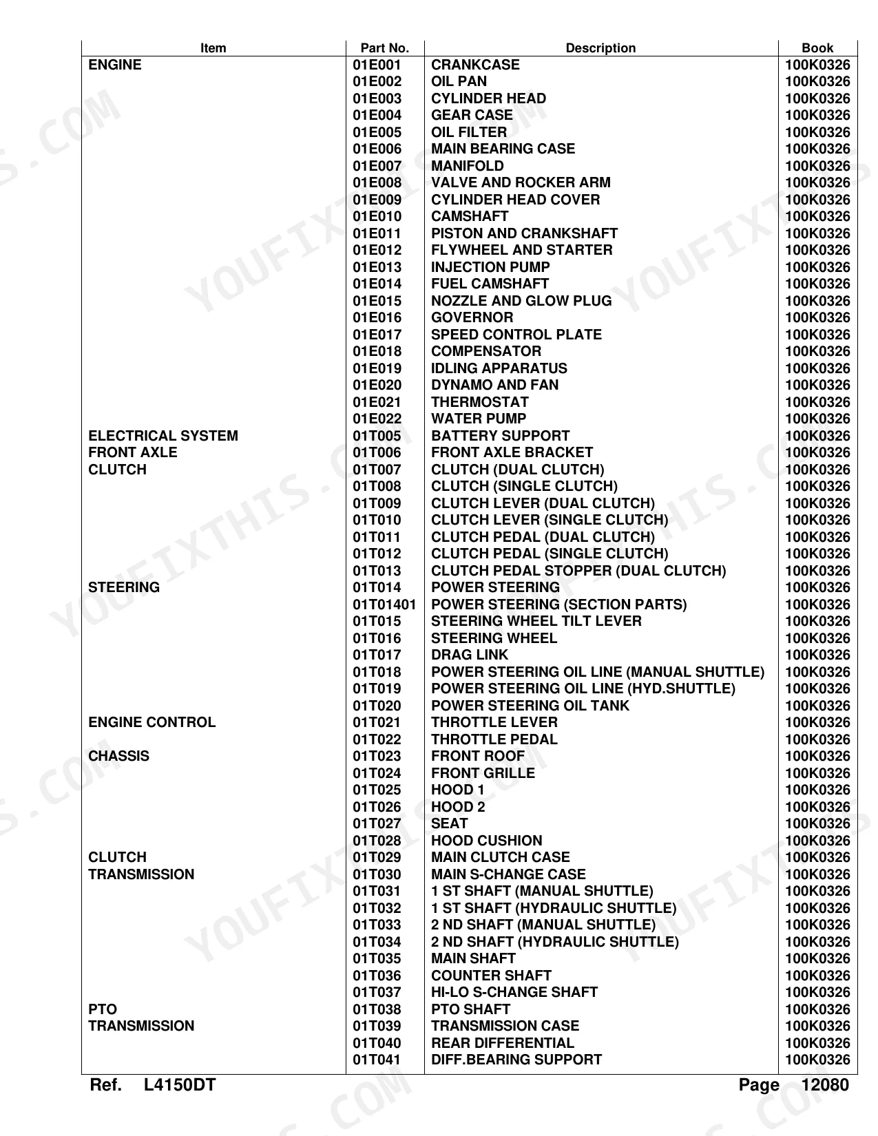


Every part on the Kubota L4150DT traces back to one OEM number, and this catalog is where you find it. Its 275 pages tie each assembly to that number, matching what's already bolted to the tractor. Engine coverage runs 44 pages, from crankcase through injection pump, governor, and water pump. Another 20 pages handle the drivetrain: transmission shafts, rear differential, and PTO. The hydraulic section spans 46 pages, including the draft control valve, shuttle valve, and 3-point linkage. Each exploded view ties a reference number to its part description, quantity, and factory weight. Need the fuel filter assembly? It's 19271-43010; the air cleaner is 17381-11010, the factory part rather than a generic stand-in. Bookmarks by system let you open the file on your phone at the parts counter and order right the first time.
What's Inside This Kubota L4150DT Parts Manual
| System | Pages | Key Topics |
|---|---|---|
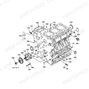
| Crankcase | 6-7 | Comp.Crankcase, Plug, Cap Sealing, Liner Cylinder, Gear Oil Pump Drive, Switch Oil |
| Oil Pan | 8-9 | Gasket, Bolt, Stud, Plug Drain, Filter Oil |
| Cylinder Head | 10-11 | Comp.Cylinder Head, Cap Sealing, Guide Inlet Valve, Guide Exhaust Valve, Gasket Cylinder Head, Thermo Unit |
| Gear Case | 12-13 | Comp.Case Gear, Cap Sealing, Pipe Water, Pin Start Spring, Gasket Gear Case, Assy Filter Oil |
| Oil Filter | 14-15 | Assy Filter Oil, Assy Cover, Comp Valve Relief, O Ring, Assy Cartridge Filte, Label Oil Filter |
| Main Bearing Case | 16-17 | Assy Case Main Brg, Bolt Bearing Case, Gasket, Cover Bearing Case, Seal Oil, Nut |
| Manifold | 18-19 | Inlet, Gasket, Bolt, Stud, Exhaust, Nut |
| Valve and Rocker Arm | 20-21 | Valve Inlet, Valve Exhaust, Spring Valve, Seal Valve Stem, Assy Shaft, Assy Rocker Arm |
| Cylinder Head Cover | 22-23 | Plate Element, Element Breather, Joint Breather Pipe, Cover Head, Gasket Cylinder Head, Plug Oil Filler |
| Camshaft | 24-25 | Tappet, Rod Push, Assy Camshaft, Gear Camshaft, Stopper Camshaft, Comp.Gear Idle |
| Piston and Crankshaft | 26-27 | Piston, Assy Piston Ring, Pin Piston, Assy Connecting Rod, Comp.Crankshaft, Gear Crankshaft |
| Flywheel and Starter | 28-29 | Comp.Flywheel, Gear Ring, Housing Flywheel, Stud, Cover, Assy Starter |
| Injection Pump | 30-31 | Joint Eye, Assy Pump Injection, Shim, Comp.Diaphragm, Assy Pipe Fuel, Clip Pipe |
| Fuel Camshaft | 32-33 | Assy Camshaft Fuel, Bearing Ball, Gear Injection Pump, Sleeve Governor, Case Governor Ball, Stopper |
| Nozzle and Glow Plug | 34-35 | Assy Nozzle, Clamp Nozzle, Pipe Injection, Plug Glow, Cord Glow Plug, Pipe Fuel Over Flow |
| Governor | 36-37 | Comp.Lever Governor, Assy Lever Fork, Shaft Fork Lever, Holder Fork Lever, Spring Start, Spring Governor |
| Speed Control Plate | 38-39 | Bolt Adjusting, Lever Speed Control, O Ring, Plate Friction, Plate Speed Control, Gasket |
| Compensator | 40-41 | Lever Compensator, Spring Return, Housing Compensator, Idle, Pin Straight, Washer |
| Idling Apparatus | 42-43 | Apparatus Idling, Assy Bolt Adjusting, Lever Engine Stop, Seal Oil, Spring Return, Support Solenoid |
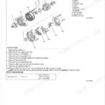
| Dynamo and Fan | 44-45 | Support Dynamo, Stay Dynamo, Pully Fan Drive, Damper Crank Shaft, Assy Dynamo, Fan |
| Thermostat | 46-47 | Flange Water, Gasket Water Flange, Pipe Water Return, Cover Thermostat, Gasket, Assy Thermostat |
| Water Pump | 48-49 | Assy Pump Water, Shaft Water Pump, Impeller Water Pump, Set Seal, Bearing Ball, Pully Fan |
| Battery Support | 50-51 | Support Battery, Retainer Battery, Base Radiator Cock, Support Radiator, Cushion, Pipe Drain |
| Front Axle Bracket | 52-53 | Bumper, Bracket Front Axle, Stud, Washer Spring, Pin Straight, Plug |
| Clutch (Dual Clutch) | 54-55 | Assy Clutch Dual, Disk Clutch, Cover Clutch, Plate Pressure, Spring Diaphragm, Kit Lever Release |
| Clutch (Single Clutch) | 56-57 | Assy Plate Pressure, Comp.Disk Clutch, Bolt, Pin Straight |
| Clutch Lever (Dual Clutch) | 58-59 | Fork Clutch Release, Key Fork, Assy Hub Clutch, Spring Release Hub, Bearing, Lever Clutch |
| Clutch Lever (Single Clutch) | 60-61 | Fork Clutch Release, Key Fork, Hub Clutch Release, Spring, Bearing, Lever Clutch |
| Clutch Pedal (Dual Clutch) | 62-63 | Rod Clutch, Turnbuckle, Heel Pedal, Bracket Switch, Arm Clutch Pedal, Spring |
| Clutch Pedal (Single Clutch) | 64-65 | Rod Clutch, Turnbuckle, Heel Pedal, Bracket Switch, Arm Clutch Pedal, Spring |
| Clutch Pedal Stopper (Dual Clutch) | 66-67 | Bolt Stopper, Stopper Pedal, Spring, Stud |
| Power Steering | 68-69 | Assy Steering Power, Pin Straight, Stud, Bolt, Clamp Cord |
| Power Steering (Section Parts) | 70-71 | Assy Steering Power, Assy Box Gear, Bearing Needle, Gasket, Seal Oil, Assy Valve Nut |
| Steering Wheel Tilt Lever | 72-73 | Base Steering, Post Steering, Holder Tilt Pin, Lever Tilt, Grip, Cover Post Rh |
| Steering Wheel | 74-75 | Shaft Steering, Bush Steering Post, Universal Joint, Assy Wheel Steering, Wheel Steering, Pad Steering |
| Drag Link | 76-77 | Arm Pitman, Link Drag, End Rod, Lever Steering, Shaft, Bolt Lock |
| Power Steering Oil Line (Manual Shuttle) | 78-79 | Comp.Pipe Return, Bolt Joint, Assy Pipe Rubber, Band Hose, Joint, Comp.Pipe Delivery |
| Power Steering Oil Line (Hyd.Shuttle) | 80-81 | Comp.Pipe Return, Bolt Joint, Assy Pipe Rubber, Band Hose, Joint, Comp.Pipe Delivery |
| Power Steering Oil Tank | 82-83 | Tank Oil, Gauge Plug, Washer Seal, Stay Tank, Clamp Band, Bolt |
| Throttle Lever | 84-85 | Joint Rod, Rod Accel., Lever Hand Accel, Grip Accel., Shaft Hand Accel., Arm Lever |
| Throttle Pedal | 86-87 | Rod Accel., Washer Plain, Pin Split, Shaft Pedal, Pin Spring, Spring, Pedal Accel. |
| Front Roof | 88-89 | Assy Roof Front, Roof Front, Net Front Roof, Bracket Upper, Nut Plate, Bracket Front Roof, Bracket Lh, Lamp Rh |
| Front Grille | 90-91 | Assy Grille Front, Grille Front, Net Front Grille, Bracket Glille Rh, Bracket Glille Lh, Support Pin, Pipe Rubber |
| Hood 1 | 92-93 | Comp.plate Upper, Hinge Bonnet, Pin Joint, Support Bonnet, Spring Bonnet Holder, Handle Bonnet Cover, Lever Bonnet Handle, Cushion Bonnet |
| Hood 2 | 94-95 | Comp.plate Side Rh, Comp.plate Side Lh, Bolt Flange, Cushion Lh, Cushion Rh, Cushion, Cushion Cover, Cushion Bonnet |
| Seat | 96-97 | Assy Seat, Bolt, Assy Suspention Seat, Shaft, Base Cushion, Support Seat, Cushion Upper, Cushion Lower |
| Hood Cushion | 98-99 | Cushion Lh, Cushion Rh, Cushion, Stopper |
| Main Clutch Case | 100-101 | Bush, Nipple Grease, Pin Straight, Stud, Washer Spring, Nut, Bolt |
| Main S-Change Case | 102-103 | Case Main S-Change, Gasket, Pin Straight, Stud, Bolt, Plug |
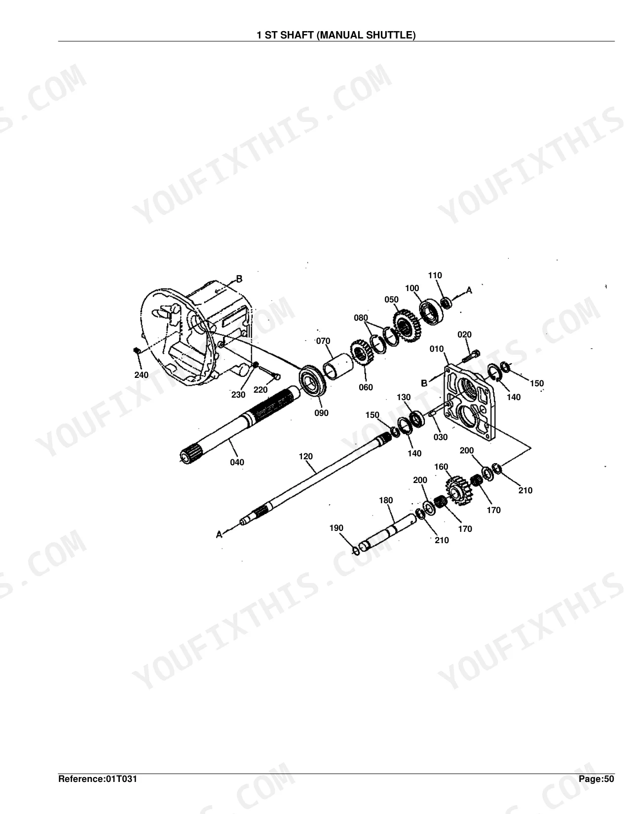
| 1 St Shaft (Manual Shuttle) | 104-105 | Case Bearing, Shaft, Gear, Collar, Bearing Ball, Shaft PTO |
| 1 St Shaft (Hydraulic Shuttle) | 106-107 | Case Bearing, Shaft, Gear, Collar, Bearing Ball, Shaft PTO |
| 2 Nd Shaft (Manual Shuttle) | 108-109 | Gear, Shaft, Race Inner, Boss Spline, Shifter, Bearing Ball |
| 2 Nd Shaft (Hydraulic Shuttle) | 110-111 | Gear, Shaft, Bearing Ball, Collar, Disk Clutch, Piston |
| Main Shaft | 112-113 | Gear, Collar, Bearing, Bearing Ball, Coupling, Shaft Main |
| Counter Shaft | 114-115 | Gear, Race Inner, Shifter, Hub Clutch, Bearing Ball, Coupling |
| Hi-Lo S-Change Shaft | 116-117 | Gear-Shaft, Bush, Gear, Collar, Bearing Ball, Shifter |
| PTO Shaft | 118-119 | Gear-Shaft, Gear, Bearing Ball, Shaft PTO, Cir-Clip Internal, Coupling |
| Transmission Case | 120-121 | Case Transmission, Gasket, Pin Straight, Plug, Washer Seal, Case PTO |
| Rear Differential | 122-123 | Assy Gear Bevel, Comp.Differential, Case Differential, Shaft Diff Pinion, Pinion Diff., Shifter Diff Lock |
| Diff.Bearing Support | 124-125 | Support Diff.Bearing, Bolt, Shim, Bearing |
| Speed Change Cover | 126-127 | Plug, Gasket, Cover, Square Ring, Gauge Oil, Base Speed Change |
| Shift Fork | 128-129 | Rod Fork, Spring Stopper, Fork Shift, Pin Spring, Support S-Change, Lever Shift |
| Main Gear Shift Lever | 130-131 | Rod Speed Change, Assy Lever, Comp.Lever, Bush, Collar, Lever Main S-Change |
| Hi-Lo Gear Shift Lever | 132-133 | Assy Fork Shift, Spring Stopper, Rod Fork, Lever Shift, Stopper Lever, Lever S-Change |
| PTO Gear Shift Lever | 134-135 | Rod Fork Pto, Assy Fork Shift, Spring Stopper, Pin Spring, Ball, Lever Shift, O Ring, Stopper Lever |
| Shuttle Shift Lever (Manual) | 136-137 | Rod Fork, Washer Seal, Fork Shift, Spring Stopper, Lever Shift, Stopper Lever, Arm Shuttle, Rod Shuttle |
| Shuttle Shift Lever (Hydraulic) | 138-139 | Collar, End Rod, Washer Spring, Nut, Rod, Lever Shuttle, Bolt, Grip Lever |
| Diff.Lock Pedal | 140-141 | Fork Shift, Cam Diff Lock, Shaft Diff Lock, Plug, Washer Seal, Shim, Spring, Support Shaft |
| Planetary Gear | 142-143 | Gear-shaft Rh, Gear-shaft Lh, Cir-clip External, Gear Planetary, Support, Pin Planetary Gear, Collar Thrust, Bearing Needle |
| Rear Axle | 144-145 | Axle Rear, Holder Carrier, Collar, Bearing Ball, Nut, Seal, Cover Rear Axle, Gasket |
| Brake | 146-147 | Case Brake Rh, Case Brake Lh, Plate Friction, Plate, Plate Cam, Ball, Spacer, Stud |
| Brake Pedal | 148-149 | Shaft Brake Pedal, Collar, Cir-clip External, Arm Brake Pedal Rh, Bush, Nipple Grease, Bolt, Wire |
| Parking Brake Lever | 150-151 | Assy Rod Brake, Rod Brake, Turnbuckle, Nut, Pin Joint, Assy Lever Brake |
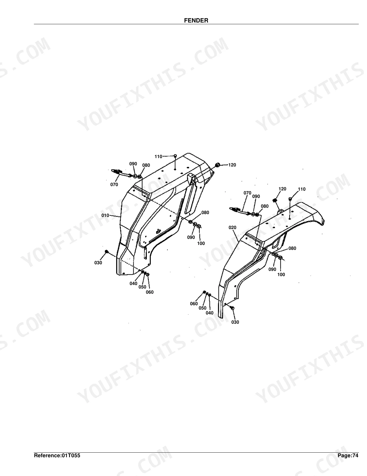
| Fender | 152-153 | Comp.Fender Rh, Comp.Fender Lh, Bolt Flange, Washer Plain, Nut, Cushion |
| Floor Seat | 154-155 | Seat Floor Rh, Seat Floor Lh, Seat Floor Middle, Support Floor Seat, Bolt Flange, Guide Lever Rh |
| Step | 156-157 | Comp.Step Rh, Comp.Step Lh, Bolt, Spacer, Cushion, Support Step Lh |
| Panel Board | 158-159 | Plate Shutter, Bolt Flange, Stud, Washer Spring, Comp.Panel, Assy Board Panel |
| Switch and Regurator | 160-161 | Assy Switch Main, Assy Key Switch, Assy Regurator, Timer, Switch, Holder Switch |
| Light | 162-163 | Assy Light Hazard, Head Lh, Bulb Light, Spring Light, Rear Combi.Rh, Rear Combi.Lh |
| Battery | 164-165 | Senser Battery, Buffer, Dry, Cord Earth, Cord Battery |
| Electrical Wiring | 166-167 | Assy Wireharness, Wireharness, Assy Box Fuse, Fuse, Cable Tractormeter, Clamp Cord |
| Fuel Tank | 168-169 | Assy Tank Fuel, Comp.Tank Fuel, Assy Cap Fuel Tank, Unit Tank, Assy Cock Fuel, Cushion Tank |
| Fuel Tank Support | 170-171 | Support Tank, Rubber Protector, Base Cushion, Cushion Upper, Retainer Cushion |
| Fuel Line | 172-173 | Assy Pipe Fuel, Clip Pipe, Spring Pipe Protect., Pipe Fuel, Clamp Cord, Support Pipe |
| Fuel Filter | 174-175 | Assy Filter Fuel, Bracket Fuel Filter, Assy Pipe Fuel, Spring Pipe Protect., Bracket Air-Cock, Comp.Support Cock |
| Fuel Filter (Section Parts) | 176-177 | Assy Filter Fuel, Assy Body, Handle Filter, Element Filter, Assy Pot Filter, Joint Breather |
| Relief Valve | 178-179 | Assy Valve Relief, Body Relief Valve, Plug, Spring, Poppet, Shim |
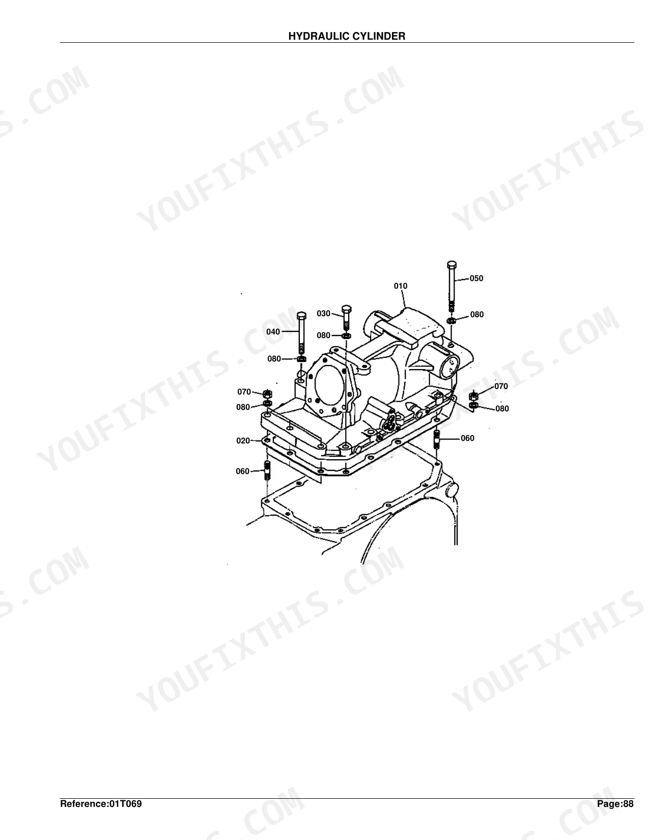
| Hydraulic Cylinder | 180-181 | Cylinder O/P, Gasket, Bolt, Stud, Nut, Washer Spring |
| Hydraulic Cylinder Cover | 182-183 | Cylinder O/P, Plug, Collar Adjusting, Shaft O/P Adjusting, Assy Valve Safety, Ring Back Up |
| Lift Arm | 184-185 | Piston O/P, Rod Oil Pressure, Arm O/P, Shaft, Bush, Retainer Arm |
| Hydraulic Control Valve | 186-187 | Valve Control, Joint Spool, Cir-clip External, Nut, Bolt, Lever Spool Drive, Arm Control, O Ring |
Quick Reference Specifications
| Specification | Value | Page |
|---|---|---|
| replacement value | Part No. 17381-11010 ASSY CLEANER AIR | p. 225 |
| Crankcase Weight (S.No. <=26364) | 58 kgf | p. 7 |
| Oil Pan Weight | 25.5 kgf | p. 9 |
| Cylinder Head Weight | 24.4 kgf | p. 11 |
| Injection Pump Assembly Weight | 3.45 kgf | p. 31 |
| Dynamo Assembly Weight | 3.47 kgf | p. 45 |
| Front Axle Bracket Bumper Weight | 30 kgf | p. 53 |
| Power Steering Assembly Weight | 16.5 kgf | p. 69 |
| Radiator Assembly Weight | 9.95 kgf | p. 229 |
| Front Wheel (9.5-20) Assembly Weight | 88 kgf | p. 269 |
| Rear Wheel (14.9-28) Assembly Weight | 254 kgf | p. 273 |
Kubota L4150DT Common Problems This Manual Covers
Hard starting, rough idle, or power loss under heavy load on the L4150DT p. 175
Start at the fuel filter section on page 175. Swap the whole unit for ASSY FILTER FUEL part #19271-43010, or if only the internal element is gone, the exploded view on page 177 lists ELEMENT FILTER part #15521-43160. Confirm your fuel lines match the diagram before ordering.
Manual Section: Fuel FilterMain hydraulic system and three-point lift feel weak, operate with jerky movements, or will not lift p. 207
Check the suction oil line diagram on page 206. Locate the hydraulic filter assembly to identify the correct replacement components. Order COMP.FILTER OIL part #36330-82630 listed on page 207 to restore proper fluid flow. Inspect the surrounding O-rings and clamps in the diagram for wear.
Manual Section: Hydraulic Oil Line (Suction)Engine misfires and blows black smoke indicating worn injector nozzles or leaking delivery lines p. 35
Pull up the nozzle and glow plug breakdown on page 34 and match it to your engine configuration. Worn injectors swap out via ASSY NOZZLE part #17331-53000 on page 35. Cross-reference the injection pipes and clamps before ordering so the fuel system seals completely.
Manual Section: Nozzle and Glow PlugHeavy dust environment causing severe air restriction and engine choking under heavy load p. 225
Examine the double air cleaner schematic on page 224. Identify the primary cleaner housing and mounting bands. Order the complete replacement ASSY CLEANER AIR part #17381-11010 listed on page 225. If reusing the housing, secure the inner element part #68335-43620 shown on page 227.
Manual Section: Air Cleaner (Double)Frequently Asked Questions
What do I get after purchasing this Kubota L4150DT manual?
A 275-page Parts Catalog in searchable PDF, ready to download the moment checkout completes. Open it on a computer, tablet, or phone with no shipping wait.
Are there any print restrictions on this Kubota L4150DT manual?
None at all. The PDF is DRM-free, so print whatever sections you want to take out to the shop. Standard letter or A4 paper works fine.
Document Quality
This PDF is a mixed document, starting with 5 pages of native digital text for instructions and index, followed by 270 pages of scanned content. An OCR layer is present, allowing you to search and copy text, though the visual quality of text on scanned pages varies from crisp to slightly faded or blurry. Diagrams are scanned images, not vector, but their labels are generally readable. Scanned pages exhibit typical artifacts like slight skewing and occasional faint lines, and one page explicitly states 'IMAGE NOT AVAILABLE' as filler.


Reviews
There are no reviews yet.