


This Service Manual covers the Gehl SL7810E skid-steer loader built with the Cummins 4B4.5T diesel engine. It is the factory manual, Gehl form number 917228, Revision A, and runs 238 pages.It is organized by system, with chapters for specifications, safety, lubrication, the mainframe, wheel drives, controls, the hydrostatic system, and the hydraulic system. You get troubleshooting guides, pressure tests, torque specifications, fluid capacities, and detailed removal and installation steps for the loader arms, cylinders, pumps, and control valves.Using this PDF download, an owner or independent shop can trace a hydraulic fault, service the lift and tilt cylinders, set charge pressure, or work through the high-flow auxiliary circuit with the same procedures the Gehl dealer network uses. Bookmarks let you move quickly to the section you need.
What's Inside This Gehl SL7810E Manual
| System | Pages | Key Topics |
|---|---|---|
| Introduction | 1 | General Information, Cummins Engine Service Manual Ordering |
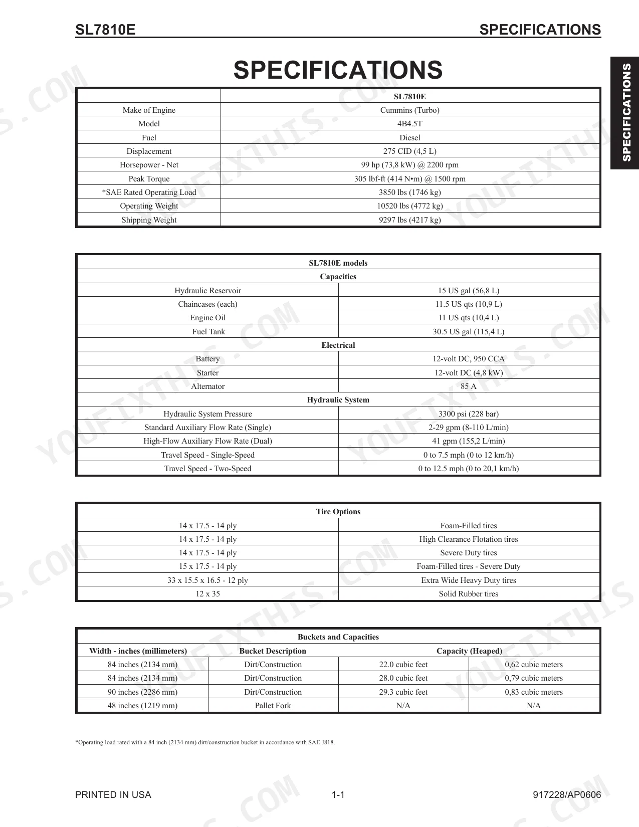
| Specifications | 1-1 | Tire Options, Buckets and Capacities, Dimensional Specifications |
| Safety | 2-1 | - |
| Lubrication | 3-1 | General Information, Hydraulic Oil Reservoir, Crankcase Oil, Chaincases, Grease Fitting Locations, Cooling System Drain Procedures |
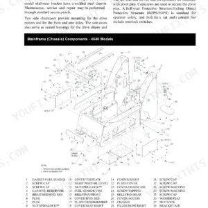
| Mainframe | 4-1 | Introduction, Engine Access Covers - Removal and Installation, Rollover Protective Structure (ROPS) Removal and Installation, Seat Removal and Installation, Seat Slide Replacement, Air Duct Removal and Installation, Air Duct Louver Replacement, Rollover Protective Structure (ROPS) Rear Window Removal and Installation, Restraint Bar Removal and Installation, All-Tach™, Power-A-Tach™ Attachment Bracket Removal and Installation, Lift Arm Removal and Installation, Rear Link Removal and Installation, Timing Link Removal and Installation, Links and Lift Arm Bushing Replacement, Control Console Removal and Installation, Floor Cover/Battery Cover Removal and Installation, Crossmember Removal and Installation, Fuel Sensor Removal and Installation, Rear Grille Removal and Installation, Rear Grille Bracket, Latch and Grille Removal and Installation, Rear Bumper Removal and Installation |
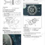
| Wheel Drives | 5-1 | Introduction, Drive Chain Adjustment, Axle Housing Assembly Removal and Installation, Drive Chain Removal and Installation, Axle and Wheel Bearing Disassembly and Assembly |
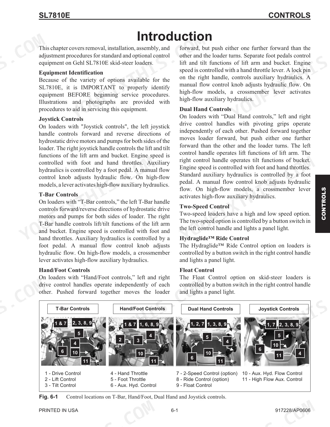
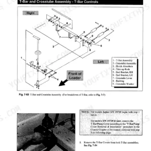
| Controls | 6-1 | Introduction, Control Handle Removal and Installation, Control Handle Position Adjustment, Drive Control Handle Tracking Adjustment, T-Bar Control Handle Assembly, Hand/Foot Control Handle Assembly, Dual Hand Control Handle Assembly, Joystick Control Handle Assembly, Pivot Tube Removal and Installation - T-Bar, Hand/Foot and Dual Hand, Neutral Centering Device Adjustment, Control Arm Assembly Removal and Installation, Lift/Tilt Control Removal and Installation, Lift/Tilt Control Adjustment, Auxiliary Hydraulics Cable Removal and Installation - T-Bar and Dual Hand, Auxiliary Hydraulics Cable Adjustment - T-Bar and Dual Hand, Auxiliary Hydraulics Cable Removal and Installation - Hand/Foot, Auxiliary Hydraulics Cable Adjustment - Hand/Foot, Throttle Cable Removal and Installation, Hand Throttle Removal and Installation, Foot Throttle Removal and Installation - T-Bar and Dual Hand, Hand Throttle Tension Adjustment, Hand Throttle Adjustment - Hand/Foot, Foot Throttle Adjustment - T-Bar and Dual Hand, High Idle Adjustment |
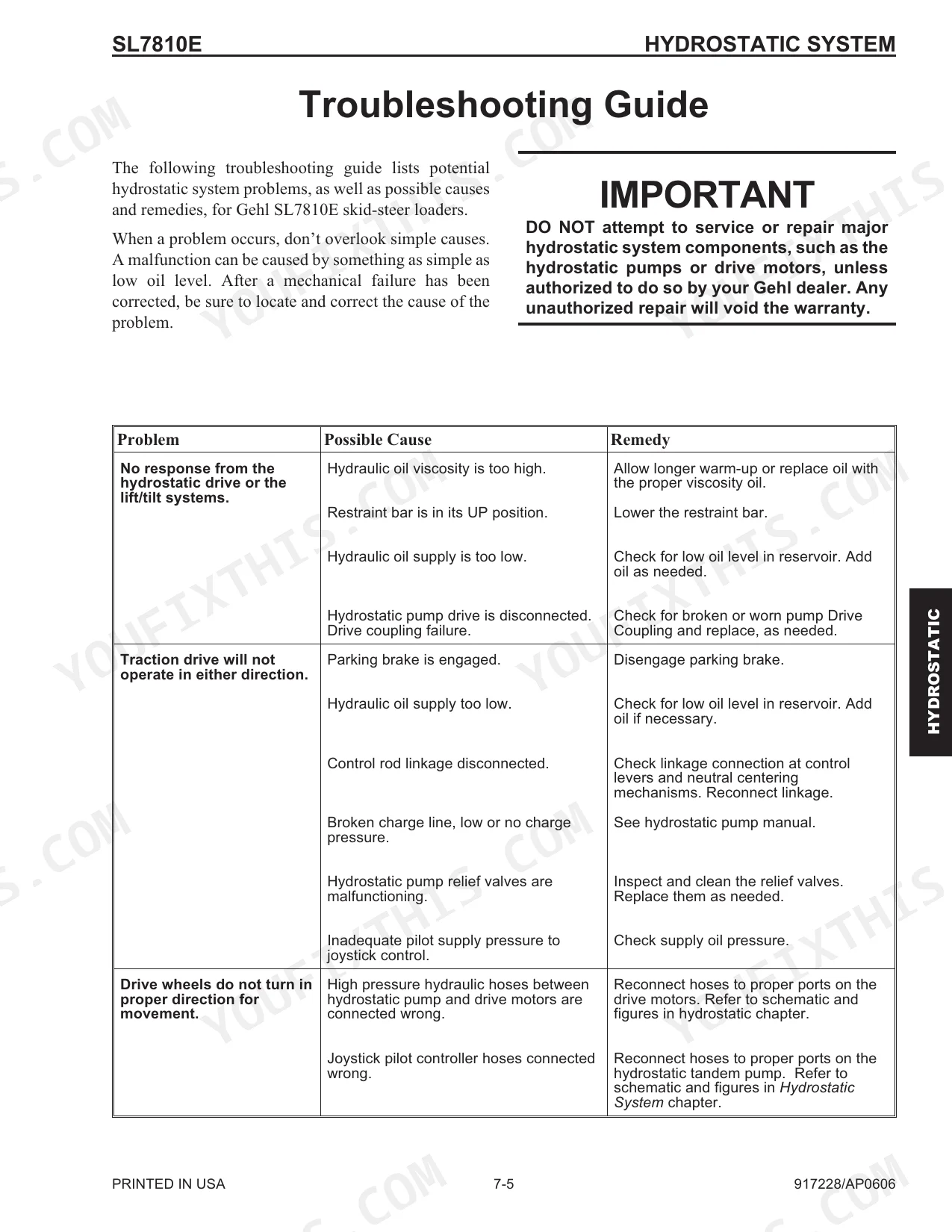
| Hydrostatic System | 7-1 | Introduction, Troubleshooting Guide, Charge Pressure Test and Adjustment, Hydrostatic Pump Relief Valves, Hydrostatic Pump Removal and Installation, Hydrostatic Pump Drive Coupling Removal and Installation, Drive Motor Removal and Installation |
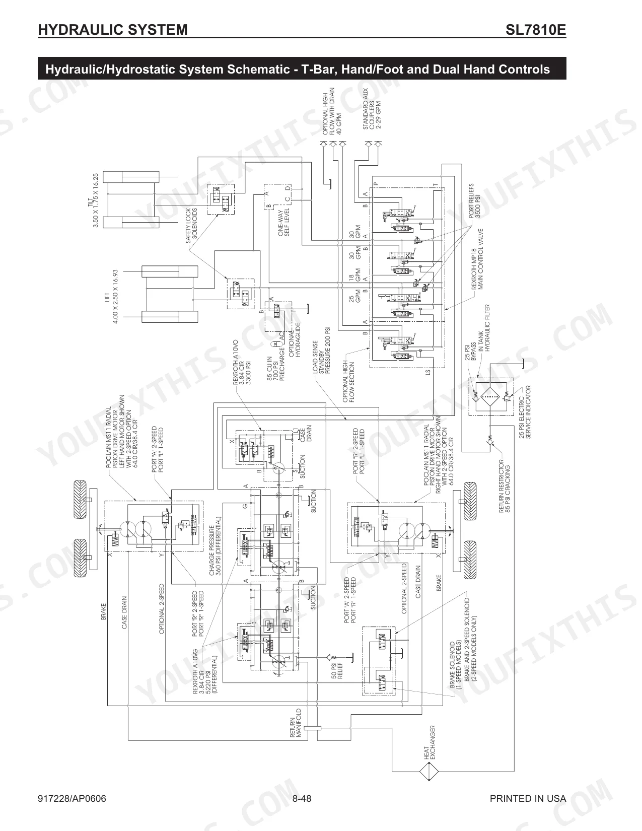
| Hydraulic System | 8-1 | Introduction, Troubleshooting Guide, Pressure Tests, System and Load-Sense Standby, Tilt Cylinder Test, Self-Leveling Valve Test, Lift Cylinder Test, Solenoid Valve Test - Safety Lock, Brake and Two-Speed, Hydraulic Oil Filter Element Replacement, Tilt Cylinder Removal and Installation, Lift Cylinder Removal and Installation, Lift and Tilt Cylinder Disassembly and Assembly, Load-Sense Axial Piston Pump Removal and Installation, Self-Leveling Valve Removal and Installation, Self-Leveling Valve Adjustment, Safety Lock Valves - Removal and Installation, Lift, Tilt and Safety Lock Valves - Disassembly and Assembly, Control Valve Removal and Installation, Control Valve Disassembly and Assembly, Load-Sense Shuttle Cleaning Procedure, Control Valve Spool Seal Replacement, Anti-Cavitation Relief Valve Removal and Installation, Spool Lock Solenoid Removal and Installation, Hydraulic Tank Removal and Installation, Hydraglide™ Accumulator Removal and Installation, Hydraulic System Schematic, T-Bar, Hand/Foot and Dual Hand Controls, Joystick Controls |
Quick Reference Specifications
| Specification | Value | Page |
|---|---|---|
| Axle housing locknuts torque | 280 ft-lbs (380 N•m) | p. 56 |
| Wheel nut torque | 240 ft-lbs (325 N•m) | p. 57 |
| Hydraulic cylinder seal replacement | A new seal kit should be installed in the leaking cylinder(s). | p. 136 |
| Fuel filter replacement | Bleed water out of fuel filter and fuel tank. Drain water separator. Add fuel conditioner. | p. 174 |
| Air filter element replacement | Replace the filter(s). | p. 174 |
| Hydraulic oil filter element replacement | Replace when the restriction indicator light on the right instrument panel comes on, indicating the return filter is restricted or, at the regular maintenance interval. | p. 141 |
| Lift solenoid valve replacement | Replace solenoid as needed. | p. 124 |
| Spool lock solenoid replacement | Check electrical connections to lock solenoid, repair as needed. If still not functioning, perform “Solenoid Valve Test” procedure in this chapter. Replace the malfunctioning switch. | p. 125 |
| High-flow auxiliary hydraulics troubleshooting | Possible causes include: Restraint bar is raised (remedy: Lower the restraint bar); Spool lock solenoid malfunctioning (remedy: Check electrical connections, repair, or replace switch); Restraint bar switch or seat switch malfunctioning (remedy: Replace switch); Load-sense signal line loose or broken (remedy: Check line, tighten or replace); Load-sense compensation not functioning (remedy: See load-sensing axial piston pump manual, replace pump if necessary); High-pressure compensation on pump not functioning (remedy: See load-sensing axial piston pump manual, replace pump if necessary). | p. 126 |
| Engine Displacement | 275 CID (4.5 L) | p. 7 |
Gehl SL7810E Common Problems This Manual Covers
High-flow auxiliary hydraulics do not work
The high-flow auxiliary circuit fails to function. A raised restraint bar, a malfunctioning spool lock solenoid, or a poor electrical connection to the solenoid are the documented causes.
Manual Section: Hydraulic System p. 126Lift arm will not raise or lower
The lift arm stays put. Check that the lift arm support device is disengaged and the restraint bar is lowered, then test the lift solenoid and its wiring.
Manual Section: Hydraulic System p. 124Hydraulic cylinder leaks or weak performance
Loss of hydraulic performance or visible leaks usually mean worn cylinder seals or leaking hose and tube fittings. A new seal kit should be installed in any leaking cylinder.
Manual Section: Hydraulic System p. 136Engine stalls or will not restart
The Cummins engine loses power, stalls, or is hard to restart after filter changes, often from air in the fuel line or clogged filters that need bleeding. The Lubrication section covers fuel and air filter service.
Manual Section: Lubrication p. 174Weak drive or no charge pressure
Sluggish or unbalanced drive can come from low charge pressure or a hydrostatic pump fault. The Hydrostatic System chapter covers charge pressure testing, adjustment, and pump service.
Manual Section: Hydrostatic System p. 119Wheel and axle hardware loosens
Loose wheel or axle hardware causes vibration and wear. Torque the wheel nuts and axle housing locknuts to the values in the Wheel Drives section.
Manual Section: Wheel Drives p. 56Frequently Asked Questions
Which loader does this manual cover?
It covers the Gehl SL7810E skid-steer loader built with the Cummins 4B4.5T diesel engine, form number 917228.
What is the hydraulic system pressure?
The specifications list a hydraulic system pressure of 3300 psi (228 bar). p. 7
What is the wheel nut torque?
The service data specifies a wheel nut torque of 240 ft-lbs (325 N•m) and axle housing locknuts at 280 ft-lbs (380 N•m). p. 57
Does it include hydraulic troubleshooting?
Yes. The Hydraulic System section includes a troubleshooting guide covering symptoms, causes, and remedies, plus solenoid and pressure tests. p. 123
How quickly can I access this manual after buying?
Download is immediate: a 238-page searchable PDF, with no shipping and no waiting. It works on any device, so you can pull it up on your phone right at the machine.
Can I print this manual?
No restrictions at all. The PDF is DRM-free, so print whatever sections you want to take out to the shop. Standard letter or A4 paper both work.
Does this Gehl SL7810E Service Manual cover the hydraulic system?
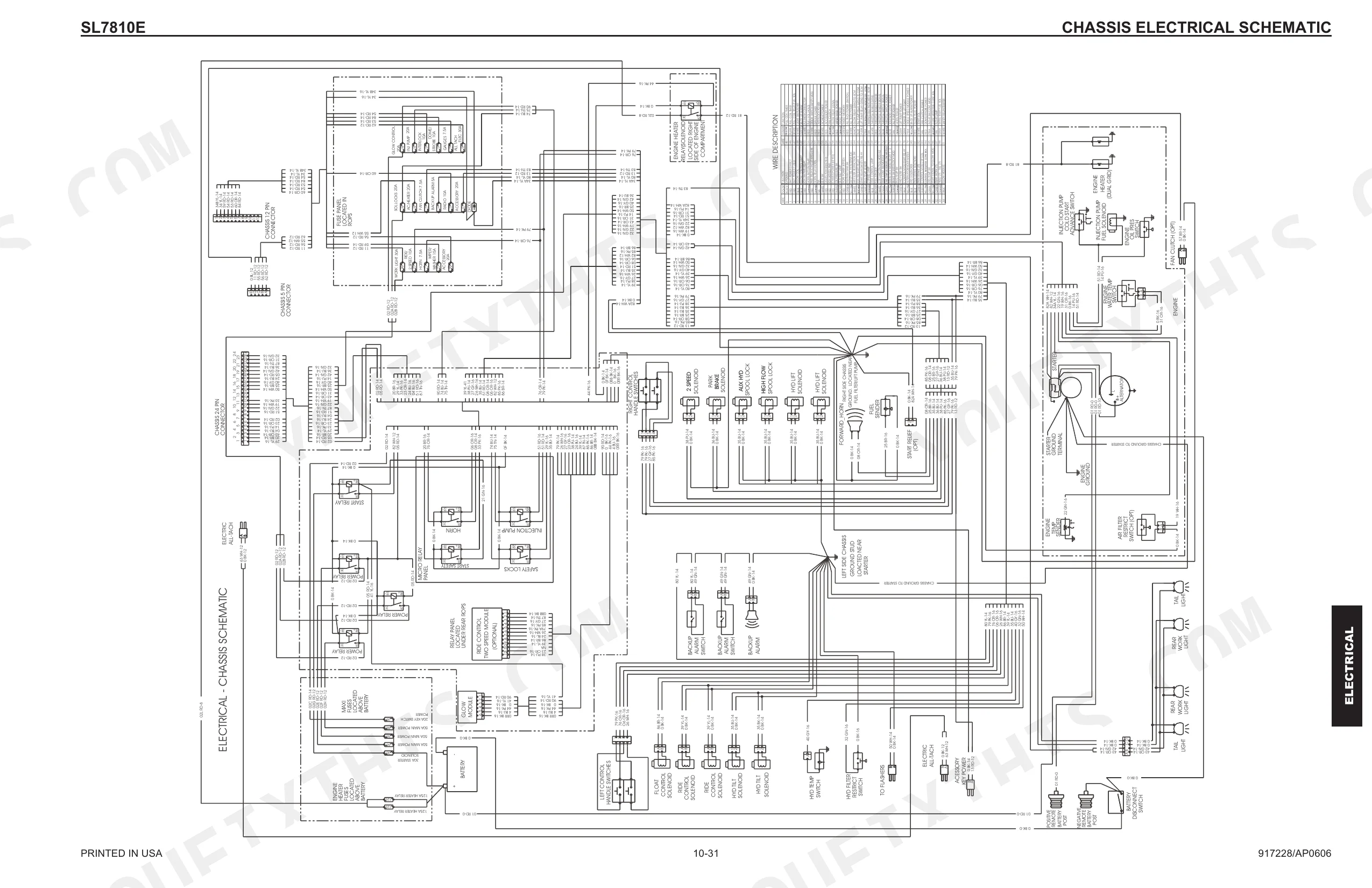
Included. Hydraulic system schematics cover all circuits, control valves, and component specifications for the Gehl SL7810E.


Reviews
There are no reviews yet.