


Built around a single machine, this Kubota LA534A-AU Workshop Manual PDF (OEM #9Y111-11440) walks your Front Loader from control valve operation through full disassembly and reassembly. It packs hydraulic schematics with complete circuit routing, electrical diagrams for solenoid valve operation on the 3rd function valve, and 10 pages of troubleshooting backed by tightening torque tables for general screws, stud bolts, UNC/UNF fasteners, plugs, and hydraulic fittings. Pin clearance at the bucket and boom cylinder holes runs 0.1 to 0.4 mm; boom cylinder head mounting bolts torque to 200 to 230 N·m. Stop hunting forum posts for numbers your loader's factory document already lists. Sections are bookmarked and the text is searchable by keyword, so you can pull up what you need at the machine.
What's Inside This Kubota LA534A-AU Manual
| System | Pages | Key Topics |
|---|---|---|
| Information | 3-12 | - |
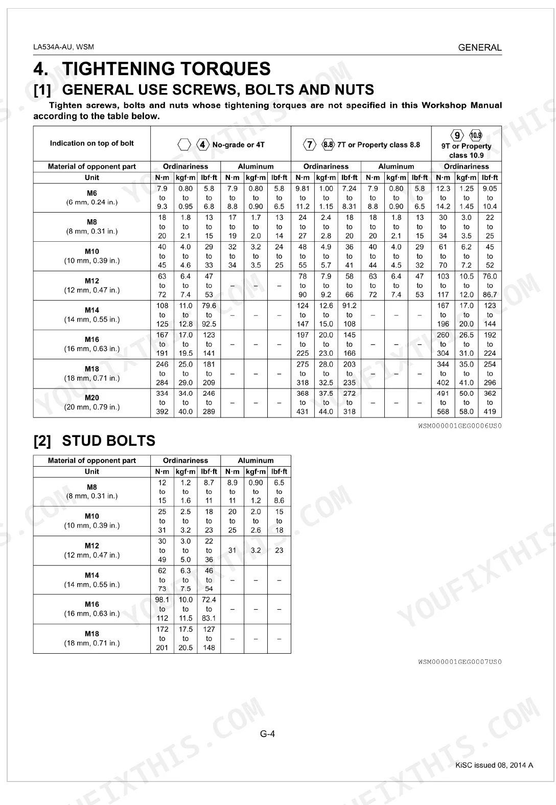
| General | 13-22 | Loader Identification, Lubricants, Tightening Torques (Stud Bolts, American Standard Screws, Bolts And Nuts With Unc Or Unf Threads, Plugs, Hydraulic Fittings) |
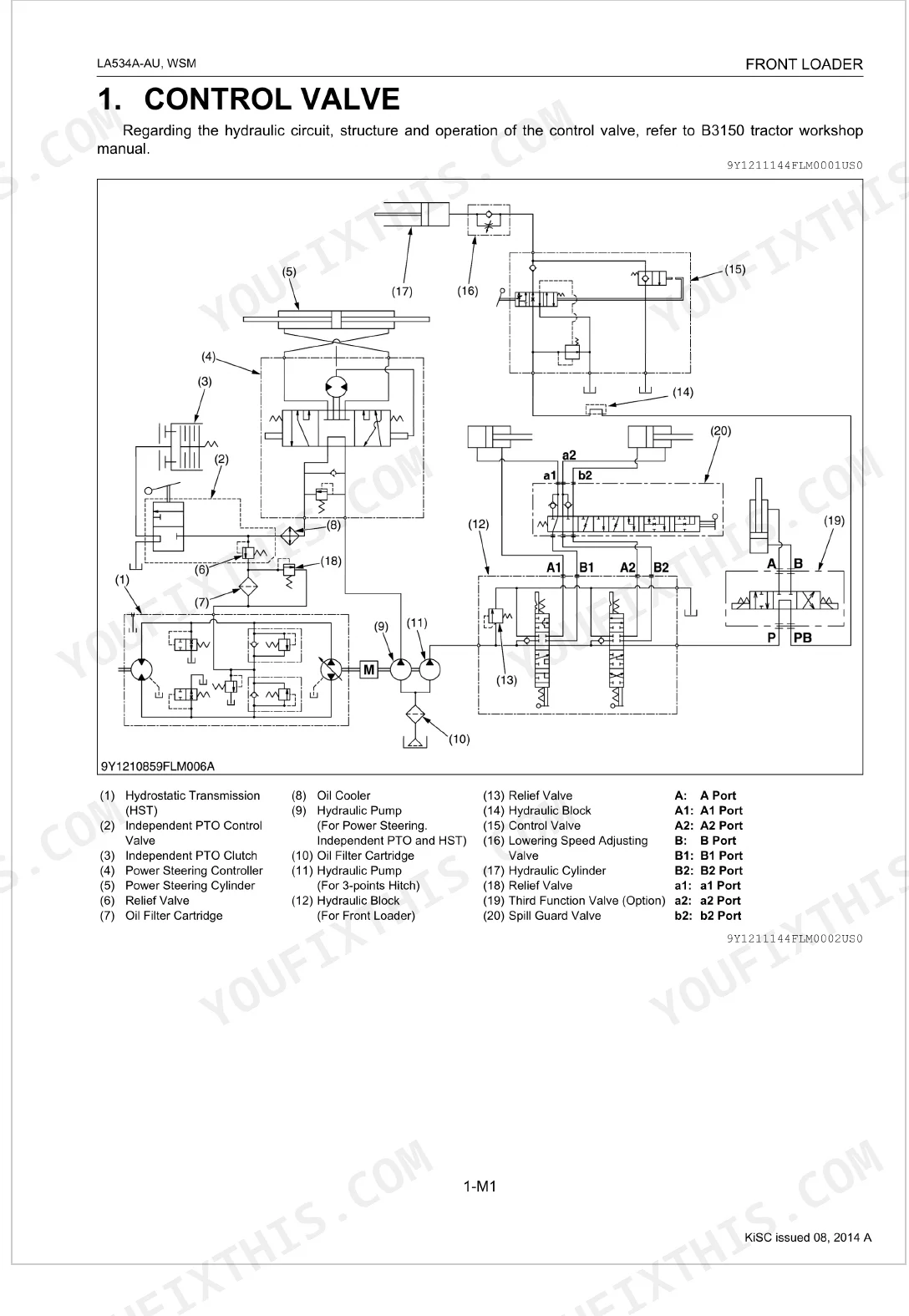
| Mechanism | 23-42 | Control Valve, 3rd. Function Valve (Hydraulic Circuit, Solenoid Valve Operation, Electrical Diagram) |
| Servicing | 43-69 | 3rd. Function Solenoid Valve, Spill Guard Linkage, Bucket, Boom, Hydraulic Cylinder, Boom Lock, Side Frame, Front Guard |
Quick Reference Specifications
| Specification | Value | Page |
|---|---|---|
| Main frame mounting bolt (M14) torque | 150 N·m | p. 55 |
| Main frame mounting bolt (M12) torque | 80 N·m | p. 55 |
| Front guard mounting bolt and nut torque | 147 N·m | p. 55 |
| Boom cylinder head mounting torque | 200 to 230 N·m | p. 55 |
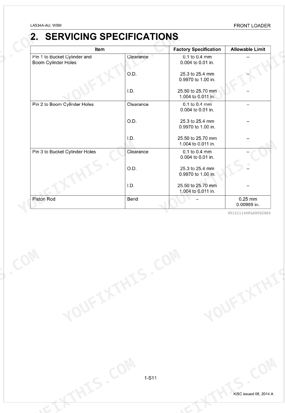
| Pin 1 to Bucket Cylinder and Boom Cylinder Holes clearance | 0.1 to 0.4 mm | p. 54 |
| Pin 2 to Boom Cylinder Holes clearance | 0.1 to 0.4 mm | p. 54 |
| Spill guard valve mounting screw (M8) torque | 24 to 27 N·m | p. 55 |
| 3rd. Function Solenoid Valve resistance (1 Terminal - 2 Terminal) | Approx. 4.8 Ω | p. 58 |
| Hose fitting, Flare nut (UNF) 9/16 torque | 22 to 25 N·m | p. 19 |
| Hose fitting, Flare nut (UNF) 3/4 torque | 36 to 40 N·m | p. 19 |
| ON - OFF Switch resistance (RB terminal - YR terminal, ON position) | 0 Ω | p. 59 |
| ON - OFF Switch resistance (RB terminal - YR terminal, OFF position) | Infinity | p. 59 |
Kubota LA534A-AU Common Problems This Manual Covers
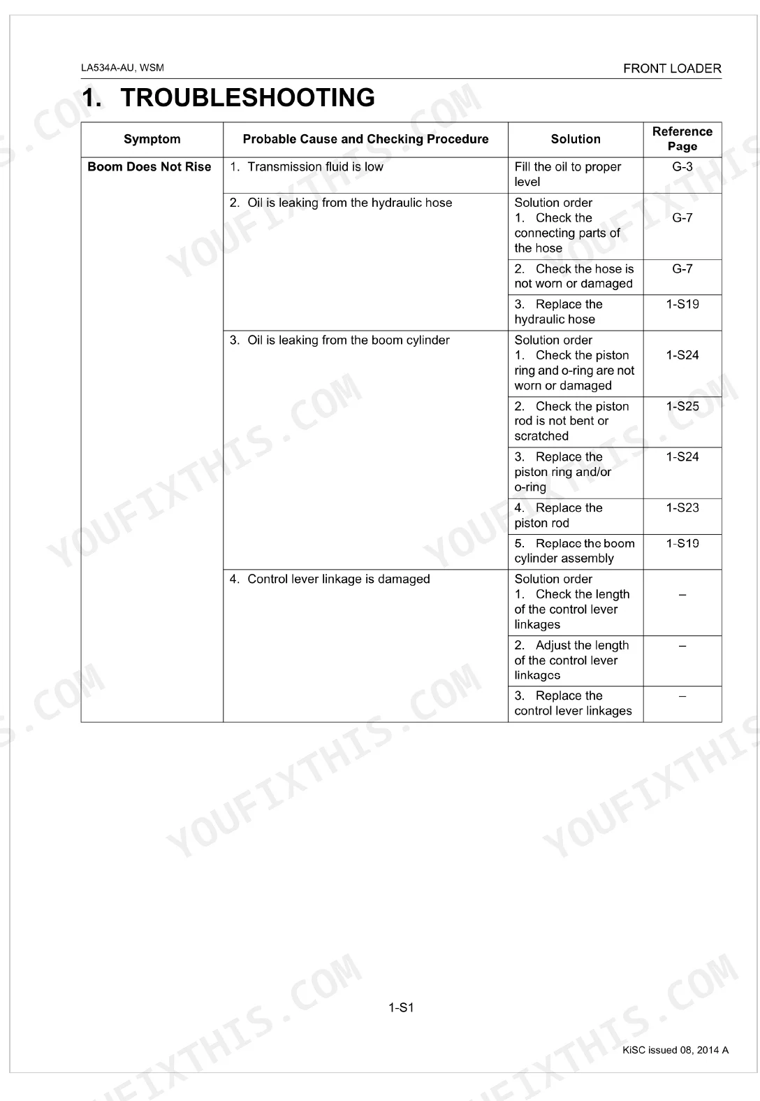
Kubota LA534A-AU boom won't rise, control lever moves freely but cylinder stays stationary p. 44
Check transmission fluid level first; it doubles as hydraulic fluid on this loader. Fill to the 15 L capacity (page 17) if low. Inspect hydraulic hoses for leaks, then follow the troubleshooting chart on page 44. If fluid is full, test the relief valve and control valve for damage before condemning the pump.
Manual Section: TroubleshootingBoom rises but cycle time is slow, won't reach full height under load p. 44
Inspect all hydraulic hoses for restrictions or pinches first. Verify transmission fluid level and top up to 15 L (page 17) if low. Check boom cylinder seals for internal bypass. Maximum system pressure is 16.6 MPa (page 11); if it tests low, the relief valve or hydraulic pump needs servicing per the troubleshooting procedures on page 44.
Manual Section: TroubleshootingBucket cylinder won't extend or retract, control lever has full travel but no movement p. 44
Start at the control lever linkage; disconnect and check for damage or binding before pulling any hydraulics. Verify transmission fluid is at the correct level (page 17). If linkage checks out, measure pin clearance at the bucket cylinder mount: service limit is 0.1 to 0.4 mm (page 68). Damaged control valve internals are the next suspect.
Manual Section: TroubleshootingLoader drops slowly on its own with engine running, won't hold height p. 44
Remove and inspect boom cylinder seals for internal leakage; a piston rod with more than 0.25 mm bend (page 54) will destroy seals quickly. Check the relief valve for wear or contamination. Test the control valve for bypass. If boom cylinder head torque is needed after reassembly, spec is 200 to 230 N·m (page 55).
Manual Section: TroubleshootingHydraulic hose fitting leaks after reconnection, new hose won't seal even when retorqued p. 19
Verify the flare nut thread size before torquing. For 9/16 UNF flare nuts, torque to 22 to 25 N·m; for 3/4 UNF fittings, torque to 36 to 40 N·m; for 7/8 UNF fittings, torque to 43 to 50 N·m. All torque specs are on page 19. Hand-tight plus an overtorqued flare nut both fail: use a torque wrench.
Manual Section: GeneralThird function auxiliary circuit won't activate, ON-OFF switch shows no response and solenoid stays open p. 58
Test the 3rd function solenoid coil resistance at terminals 1 and 2; spec is approximately 4.8 Ω (page 58). A reading of 0 or infinity means a failed coil. Verify the ON-OFF switch: RB to YR terminals should read 0 Ω in ON position and infinity in OFF (page 59). Inspect all harness connectors for corrosion or loose pins.
Manual Section: ServicingFrequently Asked Questions
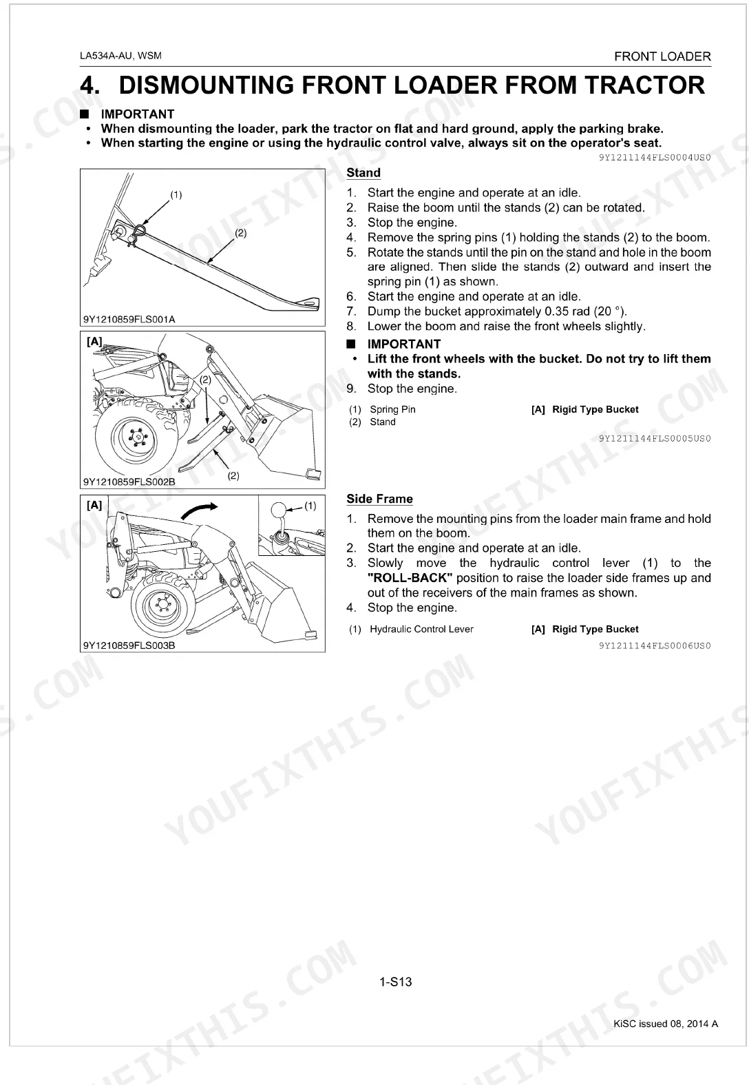
How do I remove a Kubota LA534 loader from the tractor?
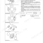
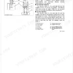
To remove the Kubota LA534 loader from the tractor, first raise the boom until the stands can be rotated, then remove the spring pins (1) and rotate the stands outward. After lowering the boom to raise the front wheels slightly and stopping the engine, remove the mounting pins from the loader main frame and slowly move the hydraulic control lever (1) to the "ROLL-BACK" position to raise the loader side frames up and out of the receivers of the main frames. Finally, disconnect the four hydraulic hoses with quick couplers and attach protective plugs (3) before backing the tractor away.
How much can the Kubota LA534 lift?
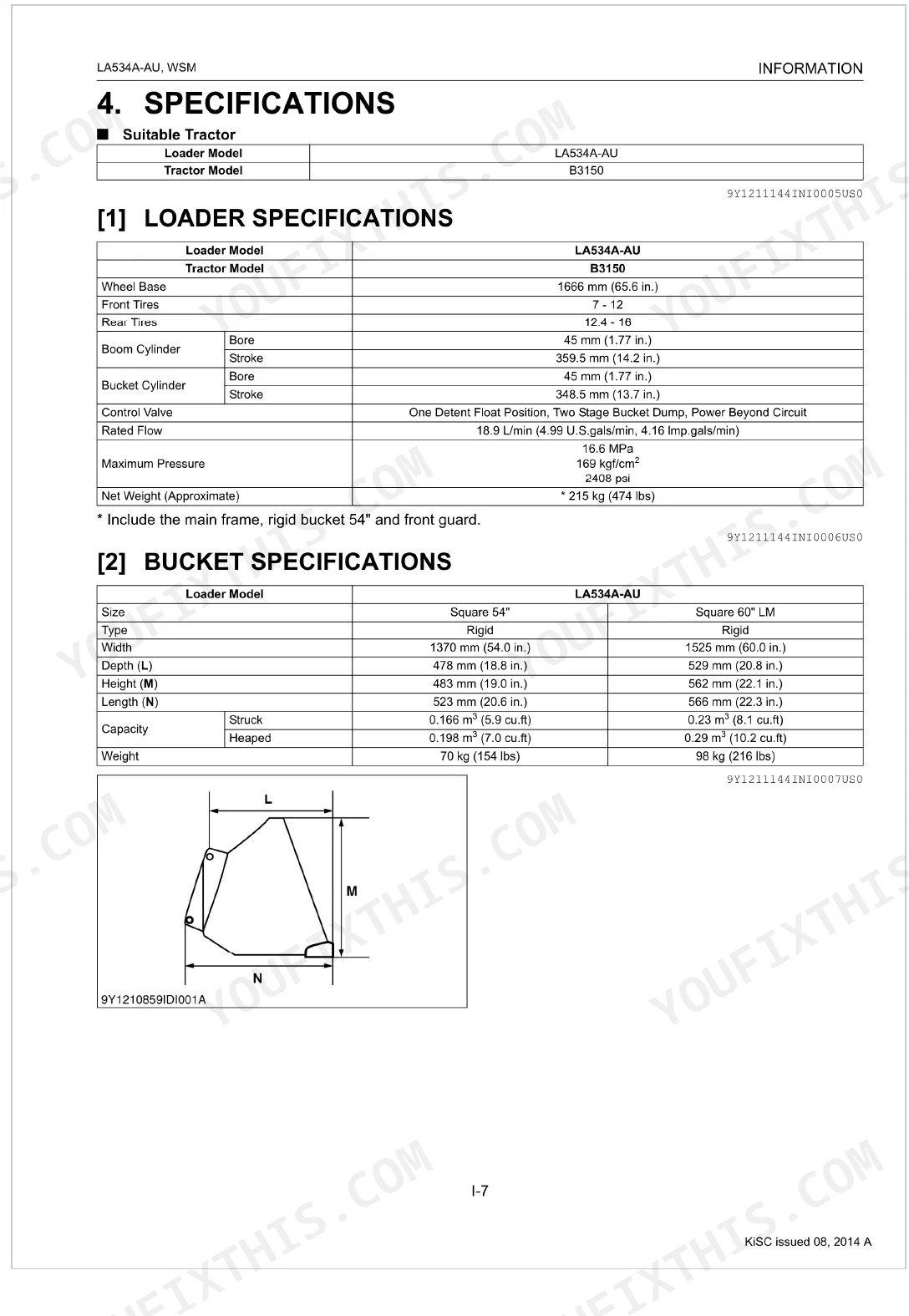
The Kubota LA534 front loader has a lift capacity of 350 kg (772 lbs) when measured 500 mm (19.7 in.) forward at maximum height. This specification is detailed in the operational specifications of the manual.
How do I grease and service a Kubota LA534 front loader?
For routine maintenance, you should grease all grease fittings on the Kubota LA534 front loader every 10 hours of operation. This is done by injecting grease with a hand grease gun into all designated fittings.
How to torque Kubota LA534 mounting bolts
When torquing the Kubota LA534 main frame mounting bolts, M14 bolts should be tightened to 150 N·m (15.3 kgf·m, 111 lbf·ft), and M12 bolts should be tightened to 80 N·m (8.2 kgf·m, 59.0 lbf·ft). It is important to check these bolts frequently, especially when new, and retighten them to the specified torque if loose.
Is this Kubota LA534A-AU Workshop Manual a digital download?
Yes. It is a 69-page searchable PDF that downloads instantly after checkout. Open it on a laptop, tablet, or phone and keep it with you on the shop floor.
Can I print this Kubota LA534A-AU manual?
Yes, print as many copies as you need; there are no restrictions. Plenty of mechanics just print the one section they're working from and take it to the bench.
Does this Kubota LA534A-AU Workshop Manual cover the hydraulic system?
Full hydraulic system diagrams are included, covering circuits, valve locations, and hydraulic component specs for the Kubota LA534A-AU.
Document Quality
This document is a native digital PDF, allowing you to search and copy the full text content. All text is crisp and easy to read throughout the manual. Diagrams and illustrations are a mix; hydraulic circuit diagrams are vector-like and remain sharp at any zoom level, while other illustrations and photos are raster images but are consistently clear with readable labels. All pages are clean and free from scan artifacts, marks, or skewed content. There are no notable blank or filler pages present in the document.


Reviews
There are no reviews yet.