

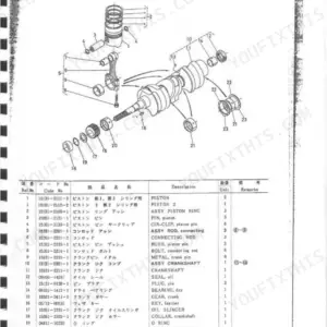
Part of the Kubota Operator Manuals.
This is the Kubota operator and service manual for the 629 backhoe, built for the B7100 tractor, and the 619B backhoe, built for the B6000 tractor, delivered as a downloadable PDF. It covers specifications, standard six-lever and optional four-lever control operation, troubleshooting, maintenance intervals, and hydraulic cylinder and valve service.
Beyond daily operation, the manual includes parts assemblies for the pump, seat swivel, belly bracket, bucket, boom, mainframe, control section, stabilizer, and hoses, with a simplified hose diagram for the full hydraulic circuit. That makes it useful for both running the backhoe correctly and repairing it.
Owners and mechanics use it to set operating pressures, rebuild leaking cylinders, service the control valves, and replace worn pins, bushings, and hoses. It is a practical reference for keeping a 629 or 619B backhoe digging cleanly.
What's Inside This Kubota 629, 619B Operator Manual
| System | Pages | Key Topics |
|---|---|---|
| Introduction and Safety Precautions | 1-2 | 629 Backhoe for B7100 Tractor, 619B Backhoe for B6000 Tractor, Backhoe and Tractor Safety, Hydraulic System Cautions |
| Specifications | 3 | Digging Depth, Reach, Bucket Sizes, Weights, Hydraulic Capacities |
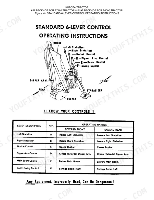
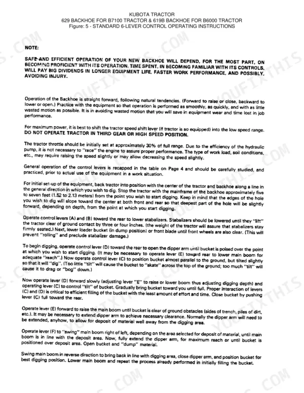
| Controls | 4-7 | Standard 6-Lever Control, Optional 4-Lever Control, Left and Right Stabilizer, Bucket, Dipper Arm, Main Boom, Boom Swing |
| Trouble Shooting | 8 | Backhoe Will Not Operate, Operates Erratically, Oil Overheating, Cylinder Leaking, Operation Slow, Valve Sticking, Excessive Wear, Relief Valve Setting 1850 PSI |
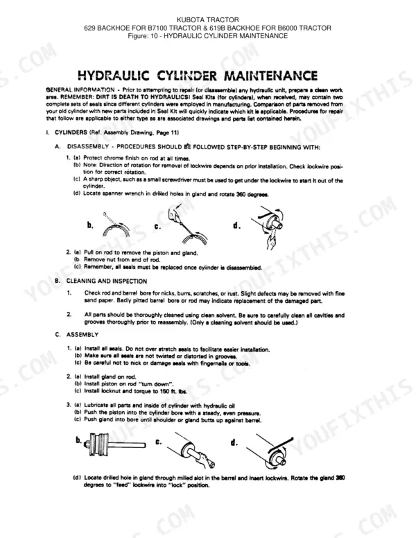
| Maintenance and Hydraulic Service | 9-13 | Lubrication, Hydraulic Cylinder Maintenance, Cylinder Disassembly Step-by-Step, Cleaning and Inspection, Cylinder Rebuild and Reassembly, Seal Kit (Piston Seal, Back-Up Seal, Rod Seal, Rod Wiper, Lock Wire), Hydraulic Valve Maintenance, Control Valve Disassembly and Assembly, Torque Specs (Piston Locknut 150 Ft-Lbs, Control Valve Tie Rods 75/100/125 In-Lbs, Spool Centering Assembly 30 In-Lbs) |
| Mounting Instructions | 14-15 | 629 Backhoe on B7100, 619B Backhoe on B6000, P.T.O. Connection, Mounted Views |
| Parts, Pump, Seat Swivel and Belly Bracket | 16-18 | Pump Assembly, Hydraulic Pump, P.T.O. Drive, Seat Swivel Assembly, Belly Bracket Assembly |
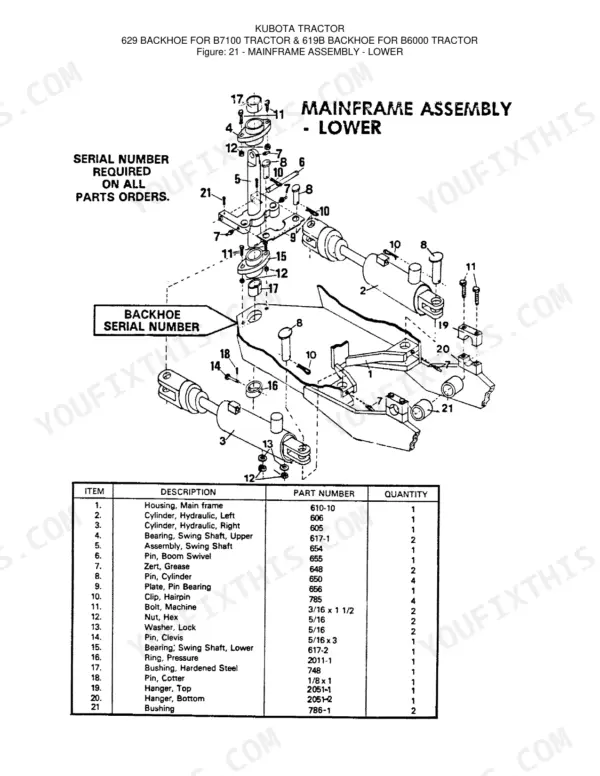
| Parts, Bucket, Boom and Mainframe | 19-22 | Bucket, Pin, Link, Bushing, Arm, Boom, Dipper, Hydraulic Cylinder, Main Frame, Swing, Upper and Lower Mainframe |
| Parts, Control Section and Stabilizer | 23-25 | Valve Assembly, Relief Valve, Connector, Adapter, 4-Lever Control Section, Right and Left Stabilizer |
| Hoses and Diagrams | 26-28 | Hose Assembly (Left Swing, Right Swing, Boom), Helpful Hints, Simplified Hose Diagram |
Quick Reference Specifications
| Specification | Value | Page |
|---|---|---|
| Cylinder Piston Locknut Torque | 150 ft. lbs. | p. 10 |
| Valve Tie Rod Torque (Final) | 125 inch lbs. | p. 12 |
| Hose, Bucket Open Length | 117 inches (297.18 cm) | p. 26 |
| Hose, Bucket Closed Length | 103 inches (261.62 cm) | p. 26 |
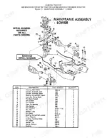
| Mainframe Assembly Machine Bolt Size | 3/16 x 1 1/2 | p. 21 |
| Grease Fitting (Zert) Part Number | 648 | p. 19 |
| Control Valve O-ring Part Number | 1058 | p. 13 |
| Hydraulic System Operating Pressure | 1800 P.S.I. | p. 3 |
| Hydraulic System Relief Valve Setting | 1850 P.S.I. | p. 8 |
| Operating Pressure | 1800 P.S.I. | p. 3 |
| Maximum Digging Depth | 6.0 ft | p. 3 |
| Swing Radius | 135 Degrees | p. 3 |
Kubota 629, 619B Common Problems This Manual Covers
Sloppy controls with excessive play
Control linkages loosen and develop slop as pivot points and bushings wear. The control section assembly shows the valve, adapter, connector, handle, and link parts you may need to tighten or replace.
Manual Section: Control Section Assembly p. 23Stabilizers or boom drift when parked
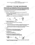
Attachments that settle after sitting point to internal cylinder or seal leakage. The hydraulic cylinder maintenance section covers disassembly, inspection, and assembly to stop the leak-down.
Manual Section: Hydraulic Cylinder Maintenance p. 10Slow or weak digging
Sluggish boom and dipper movement is often low fluid, a clogged filter, air in the system, or a worn pump. The troubleshooting chart walks each symptom to its likely cause.
Manual Section: Trouble Shooting p. 8Hydraulic leaks at hoses and fittings
Aging hoses and loose fittings seep around the swing, boom, and dipper lines. The hose assembly section identifies each hose and its routing for correct replacement.
Manual Section: Hose Assembly p. 26Cylinder seal leakage
Worn gland and piston seals let a cylinder bypass and weaken. The cylinder assembly section details the gland, piston, barrel, rod, locknut, and seal kit for a proper rebuild.
Manual Section: Cylinder Assembly p. 11Worn bucket pins and bushings
Pins, bushings, and toggle arms wear and create play at the bucket over years of use. The bucket assembly section identifies each pin, link, bushing, and tooth part.
Manual Section: Bucket Assembly p. 19Frequently Asked Questions
Which backhoes and tractors does this cover?
It covers the Kubota 629 backhoe for the B7100 tractor and the 619B backhoe for the B6000 tractor, with both standard six-lever and optional four-lever control layouts.
Does it list torque specifications?
Yes. The hydraulic cylinder maintenance section gives the cylinder piston locknut torque of 150 ft. lbs., and the manual also specifies control valve tie rod torque for reassembly. p. 10
Does it explain the four-lever and six-lever controls?
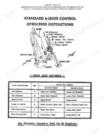
Yes. The standard six-lever control section covers stabilizer, bucket, dipper, boom, and swing operation, and a separate section adds the optional four-lever control layout. p. 4
Can I service the control valves with it?
Yes. The hydraulic valve maintenance section covers control valve disassembly and assembly, and the control valve assembly diagram identifies the outlet, valve, inlet, and seal kit parts. p. 12
What do I get after purchasing this Kubota 629 manual?
A 28-page Operator Manual in searchable PDF, ready the moment your checkout completes. Open it on a computer, tablet, or phone, with no shipping wait.
Can I print this manual?
Yes. Print as many copies as you want; there are no restrictions. Many mechanics print just the section they need and carry it to the shop floor.
Does this Kubota 629 Operator Manual include the hydraulic layout?
This is an operator manual. It includes hydraulic system reference diagrams (pages 26 and 28) and basic hydraulic specifications for operation and maintenance. It does not contain full workshop hydraulic circuit schematics with valve configurations and pressure-circuit detail, for those, the Kubota 629/619B workshop/service manual is the right source.



Reviews
There are no reviews yet.