
Part of the Kubota Operator Manuals.
This is the Kubota diesel generator Operator Manual for the GL6000, GL7000, GL9000 and GL11000 sets, including the STD, AUS, USA and USA-TM variants. It runs 62 pages, is built around the Kubota Z482 and D722 diesel engines, and is delivered as a downloadable PDF you can open on a phone, tablet or computer, or print for the job site.
It walks through generator identification and specifications, the control panel and nomenclature, the GFCI receptacle, preparing to supply power, connecting single-phase loads, pre-operation checks, and starting and stopping the engine. Service intervals, periodic service, transport and storage, troubleshooting, the automatic start and stop unit, and full wiring diagrams round it out.
With it you can reset a tripped GFCI, bleed the fuel system after running dry, size and connect a load safely, keep up the maintenance schedule, and work through the troubleshooting and warning-lamp tables.
What's Inside This Kubota GL6000–GL11000 Series Operator Manual
| System | Pages | Key Topics |
|---|---|---|
| Servicing of Generator | Generator Serial Number, Generator Model, Engine Serial Number | |
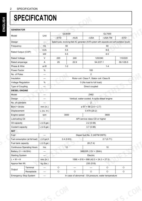
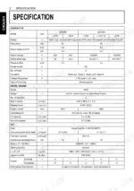
| Specifications | Generator, Diesel Engine, Set, Rated Output (Cop), Rated Voltage, Fuel Tank Capacity | |
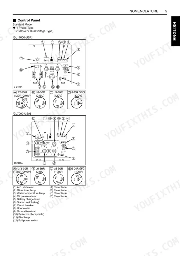
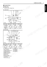
| Nomenclature | Control Panel, Fuel Tank Cap, Oil Filter Cartridge, Radiator, Air Cleaner, Battery | |
| Ground Fault Circuit Interrupter (Gfci) Receptacle | Testing Procedure, Easy Checker, Control Box, "Test" Button, "Reset" Button, Warning Lamps | |
| Preparation to Supply the Electric Power | Generator Grounding, Recommended Capacity, Connecting a Motor, Power Factor Calculations, Electrical Devices, Load Type | |
| Connecting the Load | Connection Notes, Terminal Output Model, Receptacles Output Model, Voltage Selector, Single Phase 2 Terminals Type, Single Phase 3 Terminals Type | |
| Pre-Operation Check | Door, Daily Check, Battery, Engine Oil, Coolant, Fuel | |
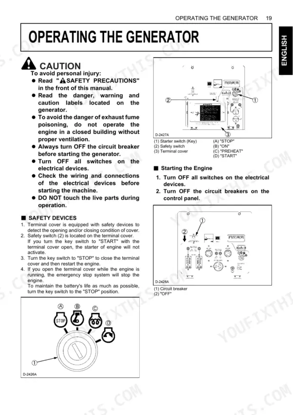
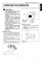
| Operating the Generator | Starting the Engine, Stopping the Engine, Fuel Lever, Main Switch, Cold Weather Starting, Circuit Breaker | |
| Service Intervals | Check of Fuel Pipes and Clamp Bands, Change of Engine Oil, Cleaning of Air Cleaner Element, Check of Battery Electrolyte Level, Engine Oil Classification, Fuel Type | |
| Periodic Service | Fuel Level, Refueling, Air Bleeding Fuel System, Engine Oil, Oil Filter Cartridge, Air Cleaner Element, Radiator, Coolant | |
| Transporting / Storage | Generator Securing, Lifting Equipment, Forklift Openings, Lifting Hook, Battery Cable, Fuel Cock Lever, Engine Coolant, Engine Oil | |
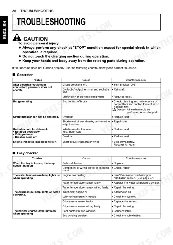
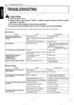
| Troubleshooting | Generator Operation, No Generation, Circuit Breaker, Output Issues, Engine Starting, Stopping, Rotation, Warning Lamps (Water Temp, Oil Pressure, Battery Charge) | |
| Automatic Start / Stop Unit (a S/S Unit) | Exterior Connection Terminal Taps (Ectt), Terminal Taps Cover (Ttc), Wiring Harnesses, Nomenclature, Connection of Terminal Taps, Wiring Diagrams | |
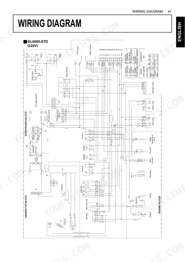
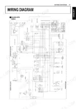
| Wiring Diagram | Gl6000-Std, Gl6000-Aus, Gl7000-Usa, Gl7000-Usa-Tm, Gl7000-Std, Gl9000-Std, Gl9000-Aus, Gl11000-Usa |
Quick Reference Specifications
| Specification | Value | Page |
|---|---|---|
| All Models | ||
| Fan belt tension (deflection) | 12 to 14 mm (0.47 to 0.55 in.) under load of 98 N (22.1 lbs.) | p. 48 |
| Fan belt check interval | Every 100 hours | p. 35 |
| Air cleaner element cleaning interval | Every 50 hours | p. 35 |
| Air cleaner element replacement interval | Every 1500 hours | p. 35 |
| Fuel filter pot cleaning interval | Every 100 hours | p. 39 |
| Fuel filter cleaning interval | Every 200 hours | p. 35 |
| Radiator hoses and clamp bands check interval | Every 200 hours | p. 35 |
| Water jacket (radiator interior) cleaning interval | Every 800 hours | p. 35 |
| Starter motor continuous running limit | 10 seconds | p. 32 |
| Lubricating oil type | API service class CD or higher | p. 14 |
| GL6000-STD, GL6000-AUS, GL7000-USA, GL7000-USA-TM, GL7000-STD | ||
| Battery model (GL6000, GL7000) | 38B20R (12V × 28Ah) | p. 14 |
| GL9000-STD, GL9000-AUS, GL11000-USA, GL11000-USA-TM, GL11000-STD | ||
| Battery model (GL9000, GL11000) | 55B24R (12V × 36Ah) | p. 15 |
Kubota GL6000–GL11000 Series Common Problems This Manual Covers
GFCI receptacle will not reset
The RESET button keeps popping back out or the outlet stays dead, which signals a ground fault or a wiring problem rather than a simple nuisance trip. The GFCI receptacle section gives the testing procedure and Easy Checker steps.
Manual Section: Ground Fault Circuit Interrupter (GFCI) Receptacle p. 20Engine cranks but will not start after running dry
After the tank empties or the fuel system is serviced, trapped air keeps the engine from firing until the system is bled. The Periodic Service section covers refueling and air bleeding of the fuel system.
Manual Section: Periodic Service p. 37Generator trips or shuts down under load
A heavy overload or a short circuit opens the breaker or protection, and the cause must be cleared before restarting. The Troubleshooting section covers no-generation and output faults and the breaker checks.
Manual Section: Troubleshooting p. 50Starter motor damage from over-cranking
Running the starter continuously past the 10-second limit can damage the motor. The Operating the Generator section covers correct starting, the fuel lever and main switch, and cold-weather starting.
Manual Section: Operating the Generator p. 31Overheating from blocked airflow or loose belt
Reduced output and overheating often come from blocked cooling air inlets or outlets, clogged radiator fins, low coolant, or a loose fan belt. The Pre-Operation Check section lists the daily checks that catch these before startup.
Manual Section: Pre-Operation Check p. 28Warning lamp for oil pressure or water temp
A lit oil pressure, water temperature, or battery charge lamp signals low oil, overheating, or a charging fault that needs attention before running. The Troubleshooting section maps each warning lamp to its likely cause.
Manual Section: Troubleshooting p. 50Frequently Asked Questions
Which generator models does this manual cover?
It covers the Kubota GL6000, GL7000, GL9000 and GL11000 diesel generators, including the STD, AUS, USA and USA-TM variants, in one 62-page operator manual.
Does it include wiring diagrams?
Yes. The Wiring Diagram section (page 53) provides model-specific diagrams for the GL6000, GL7000, GL9000 and GL11000 variants covered by the manual. p. 53
What maintenance intervals does it give?
The Service Intervals section (page 35) lists the schedule for items like the oil and fuel filter cartridges every 200 hours, the battery electrolyte check every 50 hours, and coolant change every 2 years. p. 35
How do I reset the GFCI?
The Ground Fault Circuit Interrupter section (page 20) gives the testing procedure and the TEST and RESET button sequence, along with the Easy Checker and control box details. p. 20
What format is this manual in?
Instant PDF download. The full 62-page searchable Operator Manual lands in your hands the moment payment clears. Open it on a laptop, tablet, or phone right there in the shop.
Am I able to print pages from this manual?
Yes. Print a chapter or just the pages for the job at hand, for use in your own shop. Any home or office printer works.
Does this Kubota GL6000–GL11000 Series Operator Manual have electrical diagrams?
Yes. Pages 53–62 include wiring diagrams for each series variant, from GL6000-STD through GL11000-STD, covering generator and control-circuit connections for each output configuration.





Reviews
There are no reviews yet.