


Every page here stays with one machine family: Kubota's compact excavators, the KX121-3, KX161-3, and U45-3 (OEM #97899-60550). Wiring diagrams run across six electrical sections, the hydraulic schematics map load-sensing circuits with complete fluid routing, and there are 10 pages of troubleshooting plus 30 pages of torque specs covering front attachment pins through undercarriage hardware. Error code references, maintenance interval charts for KTC/KCL/KTA and EU versions, and exploded views of the swing bracket, rubber track, and cab installation fill out the rest. Swivel bearing bolts torque to 259.9-304.0 N-m; 1/4-inch hose fittings tighten to 24.5-29.4 N-m. When a forum thread can't hand you the load-sensing relief valve adjustment sequence, this shop manual can. Download it, pull it up on a tablet at the machine, and get to work.
What's Inside This Kubota KX121-3, KX161-3 Manual
| System | Pages | Key Topics |
|---|---|---|
| I. General | 6-44 | Body And Engine Identification Marks, Safety Precautions For Servicing, Disassembly And Reassembly, Important Safty Process And Critical Functional Process, Important Inspection Items After Reassembling, Servicing Fundamentals, Maintenance Intervals, Water And Oil Quantity, Recommended Oil, Filters, Compatibility Table Of Main Components Between U45-3. And KX121-3, 161-3 |
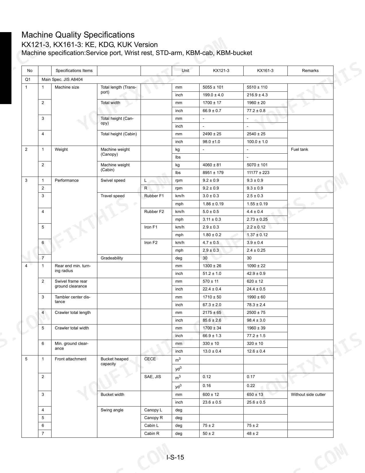
| II. Machine body(Mechanism section) | 45-72 | Product Feature, Standard Equipment, Machine Specifications, Component Interchangeability, Machine Structure |
| II. Machine body(Service section) | 73-144 | Specifications, Front Attachment, Upper Structure, Cab Installation : KTC, KCL, KTA-version, Under Carriage |
| III. Engine | 145-286 | Specifications & Features, Engine Mounting Procedure : KX121-3, 03-M Series Engine WSM |
| IV. Hydraulic system(Mechanism section) | 287-352 | Features Of Hydraulic System, Hydraulic System Specifications, Main Pump, Control Valve, Pilot Valve, Swivel Motor, Rotary Joint (Swivel Joint), Travel Motor, Hydraulic Circuit Diagram |
| IV. Hydraulic system(Service section) | 353-598 | Troubleshooting, Specifications, Relief Valve Pressure Setting, Pump, Load Sensing Control System Data, Cylinder, Swivel Performance, Traveling Performance, Testing, Disassembling And Assembling |
| V. Electrical system(Mechanism section) | 599-724 | Components, Harness Layout & Coupler, Harness Layout & Coupler : KX161-3 AI-version, Circuit Diagram, Function Of Main Circuit, Structure And Function Of Main Components |
| V. Electrical system(Service section) | 725-801 | Wire Harness Installation, Troubleshooting, Electrical Equipment Specifications |
| VI. Optional Unit : Air Conditioner(Mechanism Section) | 802-882 | Air Condition System, Function And Structure, Electrical System, Technical Terms |
| VI. Optional Unit : Air Conditioner(Service Section) | 883-970 | Troubleshooting, Servicing Specifications, Regular Check And Service Points, Precautions At Repairing Refrigerant Cycle, Precaution For Installation And Maintenance, Checking And Charging Refrigerant Cycle, Main Components Servicing |
| VII. Optional Unit (KTC) : Angle Dozer (KX121-3) | 971-994 | Specifications, Machine Quality Specifications, Lubrication Point Of Angle Dozer, Dozer Lever, Control Valve, Rotary Joint, Under Carriage, Hydraulic Circuit |
Quick Reference Specifications
| Specification | Value | Page |
|---|---|---|
| Swivel Bearing Tightening torque | 259.9 ~ 304.0 N·m (26.5 ~ 31.0 kgf·m) 191.7 ~ 224.2 ft·lbs | p. 108 |
| Tightening torque for mounting track roller | 259.9 ~ 304.0 N·m (26.5 ~ 31.0 kgf·m) 191.7 ~ 224.2 ft·lbf | p. 144 |
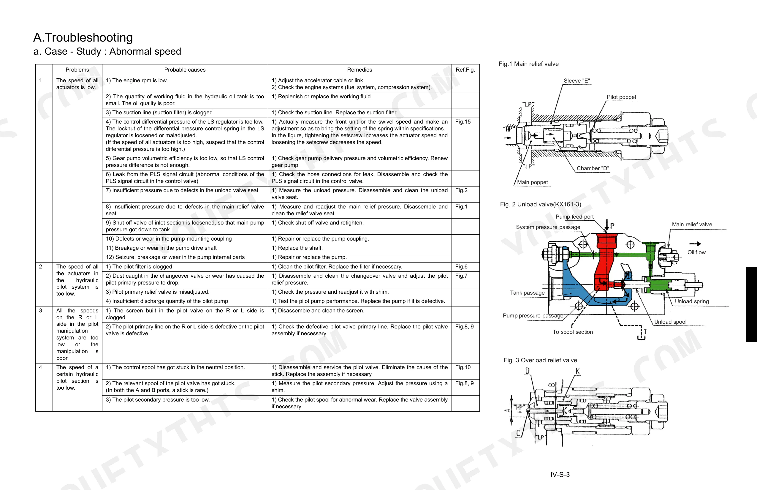
| Main relief valve adjustment procedure | 1. Loosen the lock nut of the relief valve. Using a hex wrench, turn the adjusting screw to reach the specified setting. Then tighten up the lock nut. Clockwise turn raises the pressure, and counterclockwise turn lowers it. 2. Run the engine at the maximum speed. Move the levers and make sure the pressure setting. | p. 398 |
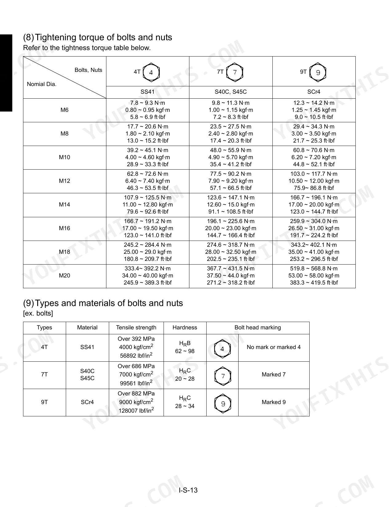
| Hose screw tightening torque (1/8") | 7.8 ~ 11.8 N·m | p. 16 |
| Hose screw tightening torque (1/4") | 24.5 ~ 29.4 N·m | p. 16 |
| O-ring installation procedure | Clean up the O-ring groove and deburr its edge as required. Before installing the ring, be sure to apply lubricant (grease) over it. (Do not do this to the floating seal.) Fit the O-ring into its groove without twist. With your fingertip, push the ring gently and evenly into the final position. Otherwise the ring would easily get twisted in contact with the inner edge of the groove. | p. 13 |
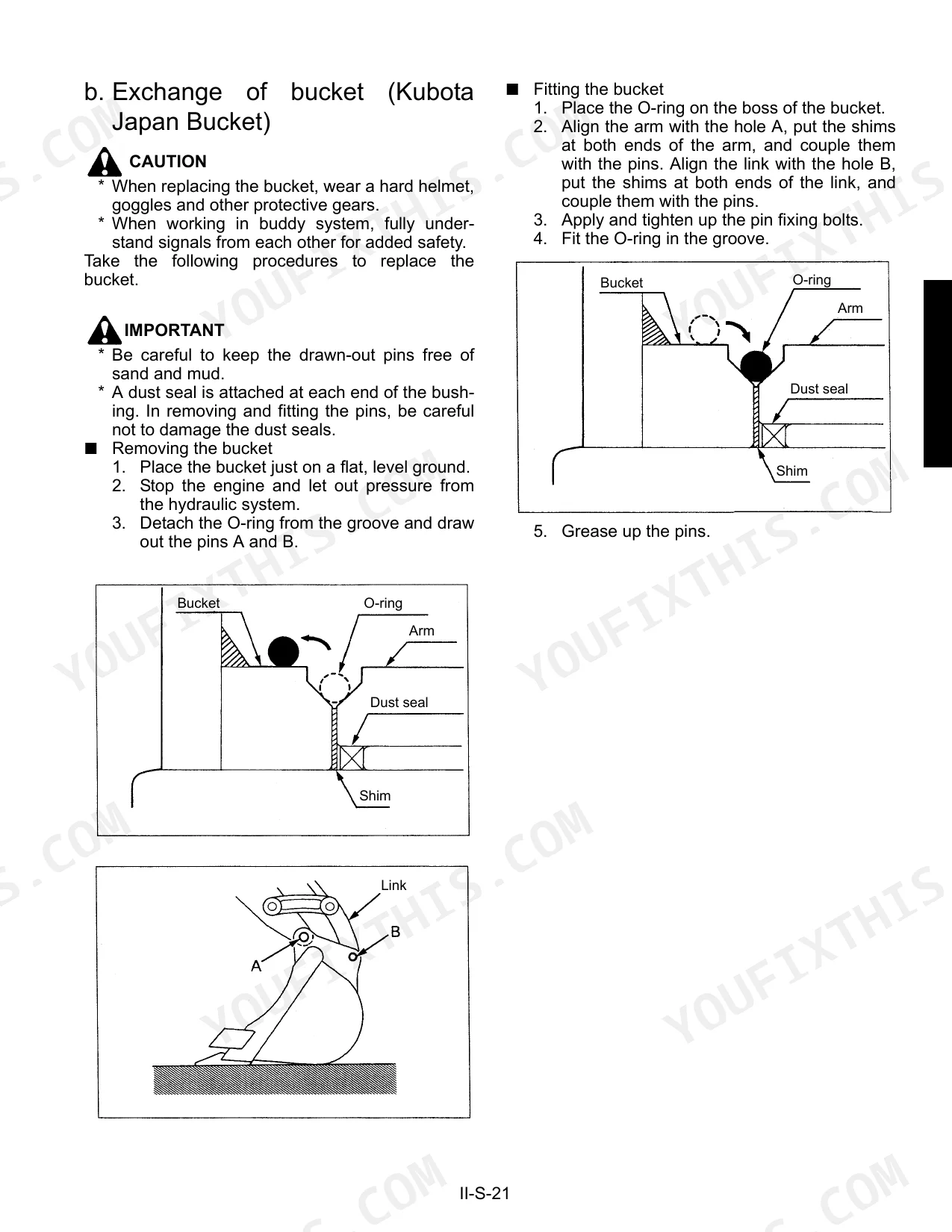
| Dust seal installation procedure | Install the dust seals in the direction as shown at left. If in the wrong direction, the sealing effect is adversely affected, which may get the pins worn out earlier. | p. 95 |
| Oil seal installation procedure | Do not confuse the orientation of the oil seal lips. Direct the main lip toward the oil chamber; in other word, toward what is to be sealed. If in dry state, the oil seal may wear out when running in the machine. To prevent this, be sure to apply lubricant (grease) over the lip sliding surface. If provided also with a dustproof lip, fill the space between this lip and the main lip with grease. As a rule, use a press to press-fit the oil seal. If not available, allpy a suitable tool and tap it evenly without allowing any tilt. Press-fit the oil seal deep down to the bottom of the oil seal fitting boss. | p. 14 |
| Swivel motor oil seal installation procedure | Apply grease to the lip and outer surface of the oil seal. Fit it into position using the jig. | p. 505 |
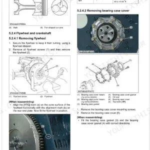
| Main bearing case screw 1 tightening torque | 46.1 to 50.9 N·m (4.7 to 5.2 kgf·m) 34.0 to 37.6 ft-lbs | p. 247 |
| Swivel motor taper roller bearing installation procedure | Press-fit the outer race of the taper roller bearing fully into the gear case. | p. 505 |
| Idle gear bushing installation procedure | 1. Clean a new idle gear bushing and idle gear bore, and apply engine oil to them. 2. Using an idle gear bushing replacing tool, press in a new bushing (service parts) to the specified dimension. | p. 255 |
Kubota KX121-3, KX161-3 Common Problems This Manual Covers
Kubota KX121-3 hydraulic hose leaking at fitting after replacement, implement response sluggish p. 16
Inspect each hose fitting for proper sleeve seating before torquing. For 3/8" screws, torque to 49.0~53.9 N·m (page 16). Check routing for contact points and twist, then cycle all implements at full stroke. If response stays sluggish, verify hydraulic oil is at the 75 L full mark and look for air ingestion at suction connections.
Manual Section: IV. Hydraulic system(Service section)After wiring harness service, engine cranks weakly or starter solenoid won't engage p. 742
Check battery voltage first, then inspect every connector disturbed during service using the procedure on page 742. Push each terminal fully home and verify lance engagement. Confirm all harness clamps seat to their stoppers per page 727, with white tape markings clamped securely. Trace the harness for contact with sharp body edges or exhaust components.
Manual Section: Electrical System Troubleshooting (General)Boom lifts slowly or arm digs with reduced force, hydraulic pressure suspect
Begin with the hydraulic troubleshooting sequence, then gauge the main relief valve pressure at maximum engine speed: 24.5 MPa for the KX121-3, 23.5 MPa for the KX161-3 (page 374). If it reads low, loosen the lock nut and turn the adjusting screw clockwise per the procedure on page 398, then recheck at full engine speed.
Manual Section: Hydraulic System Troubleshooting (Abnormal Speed, Weak Power, Poor Manipulation)Track roller loose or knocking after undercarriage overhaul, vibration through cab felt p. 144
Remove the track and clean all roller mounting faces. Torque every roller mounting bolt to 259.9~304.0 N·m (page 144), working in a cross pattern to seat the flanges evenly. Reinstall the track and drive the machine slowly in both directions on flat ground. Any knock or vibration that persists after correct torque points to a worn or damaged roller.
Manual Section: II. Machine body(Service section)Swing bearing grinding or excessive play, upper structure slews uneven or jerky p. 108
Clean all swivel bearing mating surfaces and bolt holes before assembly. Torque the bearing mounting bolts to 259.9~304.0 N·m (page 108), tightening opposing bolts in stages to seat the race evenly. After that, rotate the upper structure through a full 360-degree slew at low speed and listen for grinding. Any roughness that lingers points to contamination inside the race or inadequate grease.
Manual Section: II. Machine body(Service section)Oil seal on cylinder leaks after rebuild, rod surface wet or weeping p. 553
Disassemble the cylinder head and verify seal orientation. The main lip must face the oil chamber; grease the sliding surface before installation per page 14 or it will wear immediately on startup. Follow the numbered installation sequence on page 553: seat the mud scraper ring (Mark 6) with a press and the piston rod seal (Mark 4) with 3-finger pliers.
Manual Section: IV. Hydraulic system(Service section)Frequently Asked Questions
What do Kubota KX121-3 error codes mean?
On the KX121-3, error codes show up as blinks on the system lamp. A 'Water temperature sensor line break' gives a '-' (no blinking) in operating mode, an 'Acceleration sensor line break' blinks 2 times, a 'Governor sensor line break' 3 times, and an 'AI motor drive line break' 4 times.
What do Kubota KX161-3 alarm codes mean?
The KX161-3 reports alarm codes through the system lamp's blink count. No blink ('-') in operating mode means a 'Water temperature sensor line break'; 2 blinks signals an 'Acceleration sensor line break', 3 blinks a 'Governor sensor line break', and 4 blinks an 'AI motor drive line break'.
How do I clear fault codes on a Kubota KX121-3?
Enter service mode first: disconnect the 8-pin coupler from the AI controller and switch the AI operation switch to OFF. From there, open the 'Fail record delete menu (7)', then toggle the AI operation switch ON and then OFF. The fail records clear, and the green AI operation lamp blinks 11 times once they are all gone.
How to reset Kubota KX121-3 service light
Resetting the service light means clearing the fail records through the 'Fail record delete menu (7)' in service mode. Get into service mode by unplugging the 8-pin coupler at the AI controller and setting the AI operation switch to OFF. Cycle that switch ON then OFF to wipe the records; the green AI operation lamp blinks 11 times to confirm.
What do I get after purchasing this Kubota KX121-3, KX161-3 manual?
Checkout gets you a 994-page searchable PDF, downloadable right away. Open it on a laptop, tablet, or phone and take it straight to the shop floor.
Am I able to print pages from this Kubota KX121-3, KX161-3 manual?
None at all. The PDF is DRM-free, so print whatever sections you want to carry out to the shop. Standard letter or A4 paper works fine.
Does this Kubota KX121-3, KX161-3 Workshop Manual cover the hydraulic system?
Included. Hydraulic system schematics cover all circuits, control valves, and component specifications for the Kubota KX121-3, KX161-3.
Document Quality
This document is a scanned PDF with an OCR layer, allowing you to search and copy the full text. The main body text is generally crisp and readable throughout. Diagrams and illustrations are scanned images; while their labels are mostly clear, some finer details may lose sharpness at high zoom levels. Pages are clean with a consistent white background, and there are several blank pages interspersed, such as pages 4, 44, 46, 60, 64, 72, and 74.

Reviews
There are no reviews yet.