
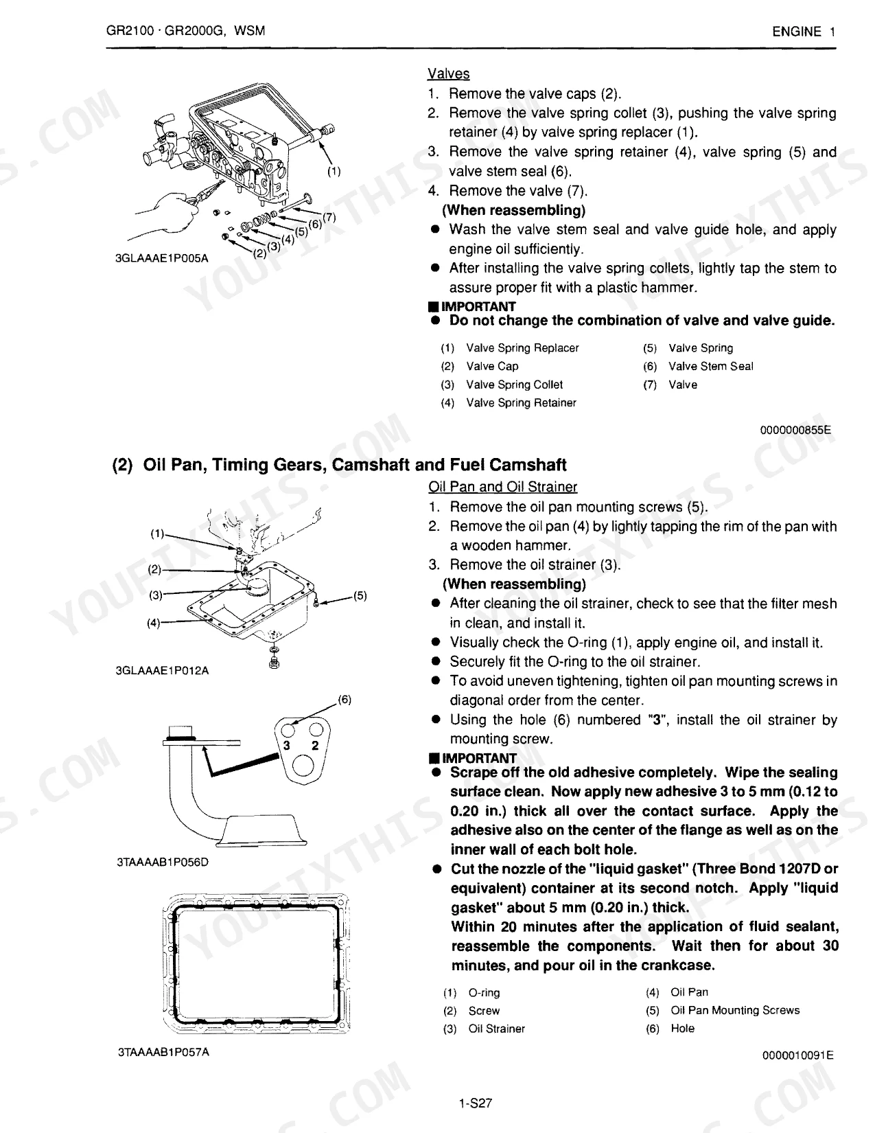
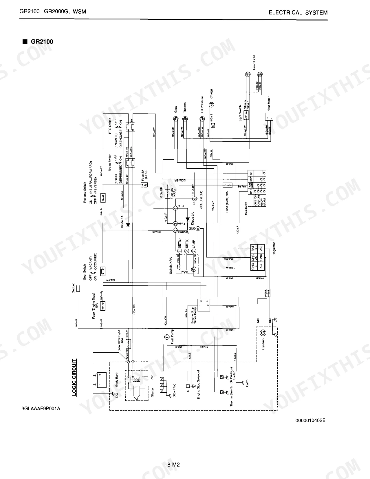
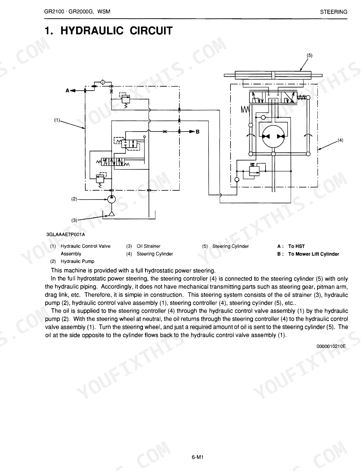
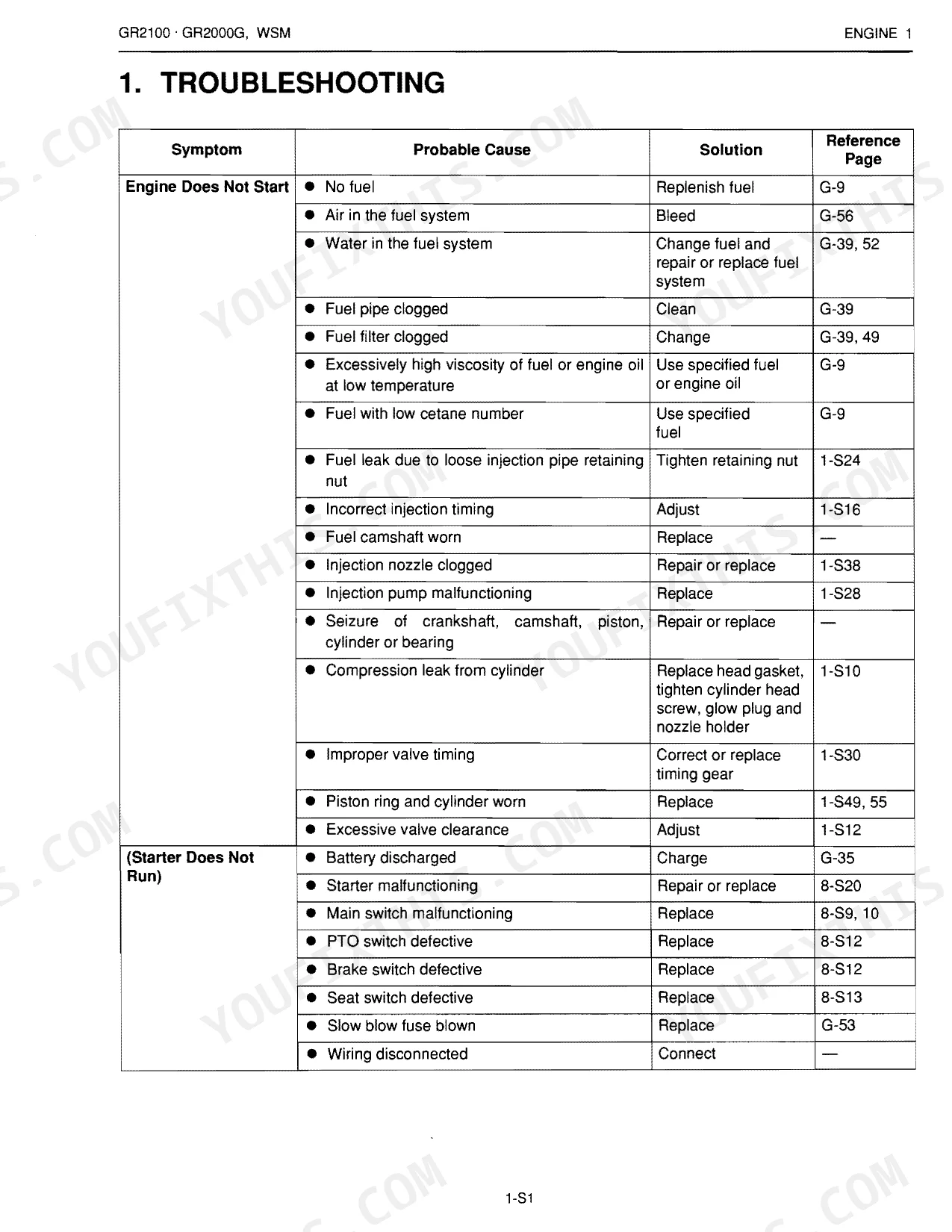
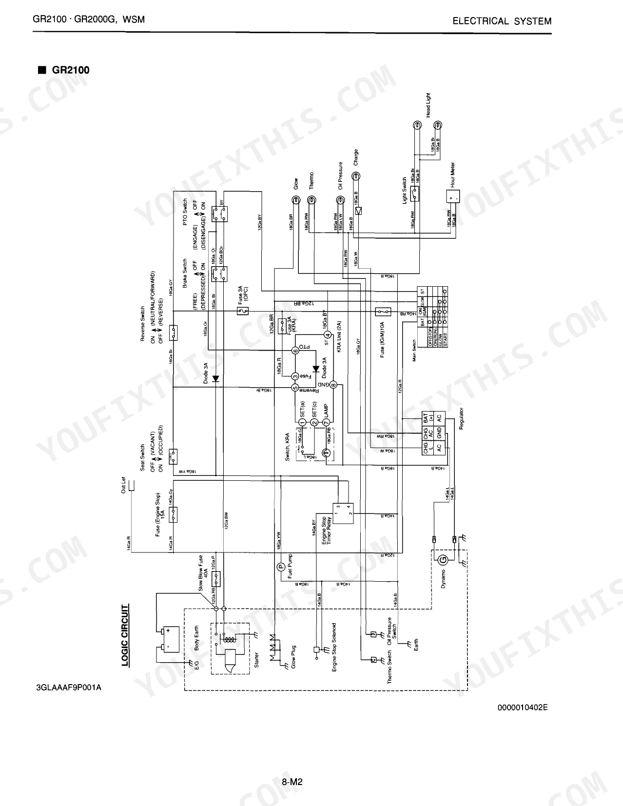
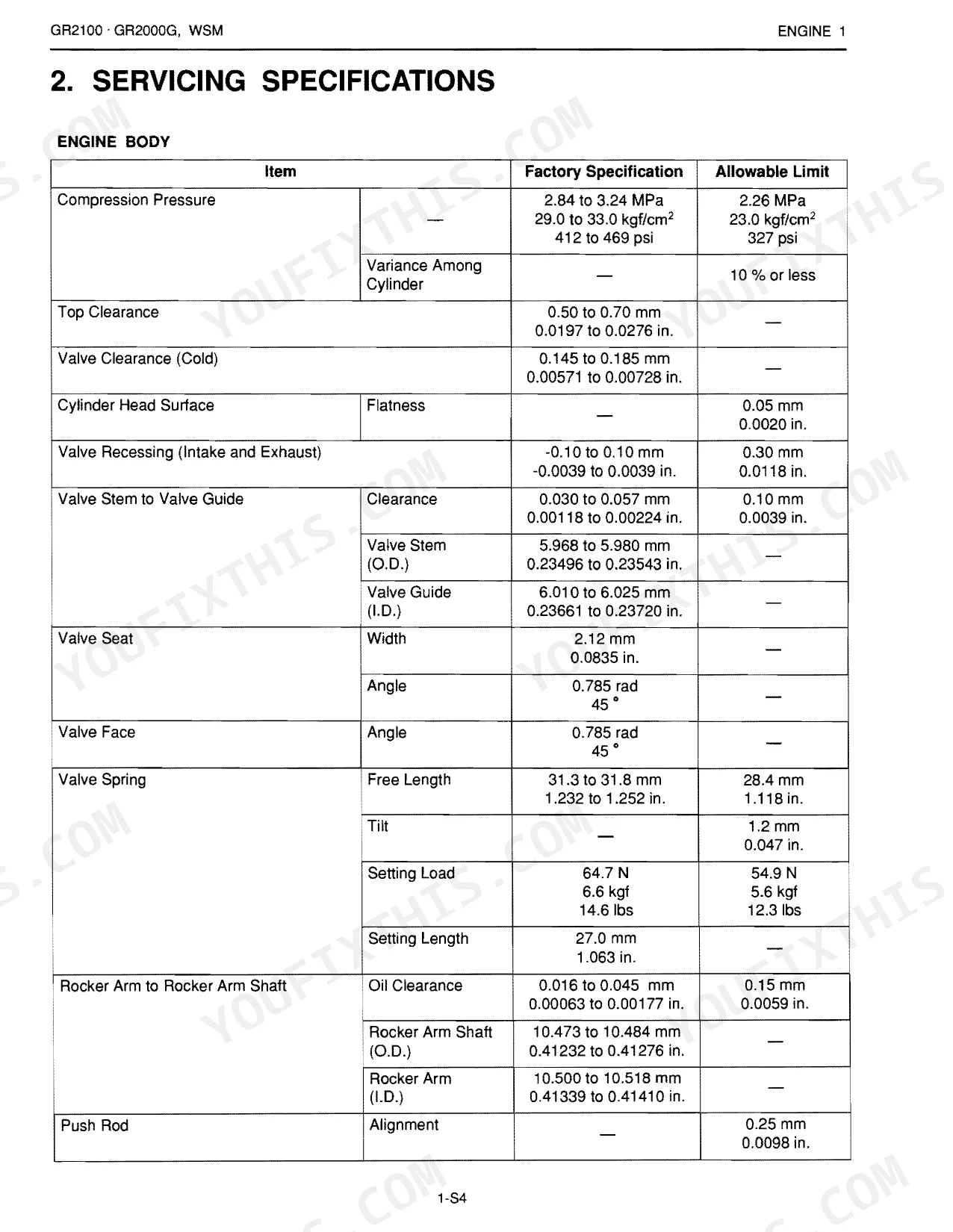
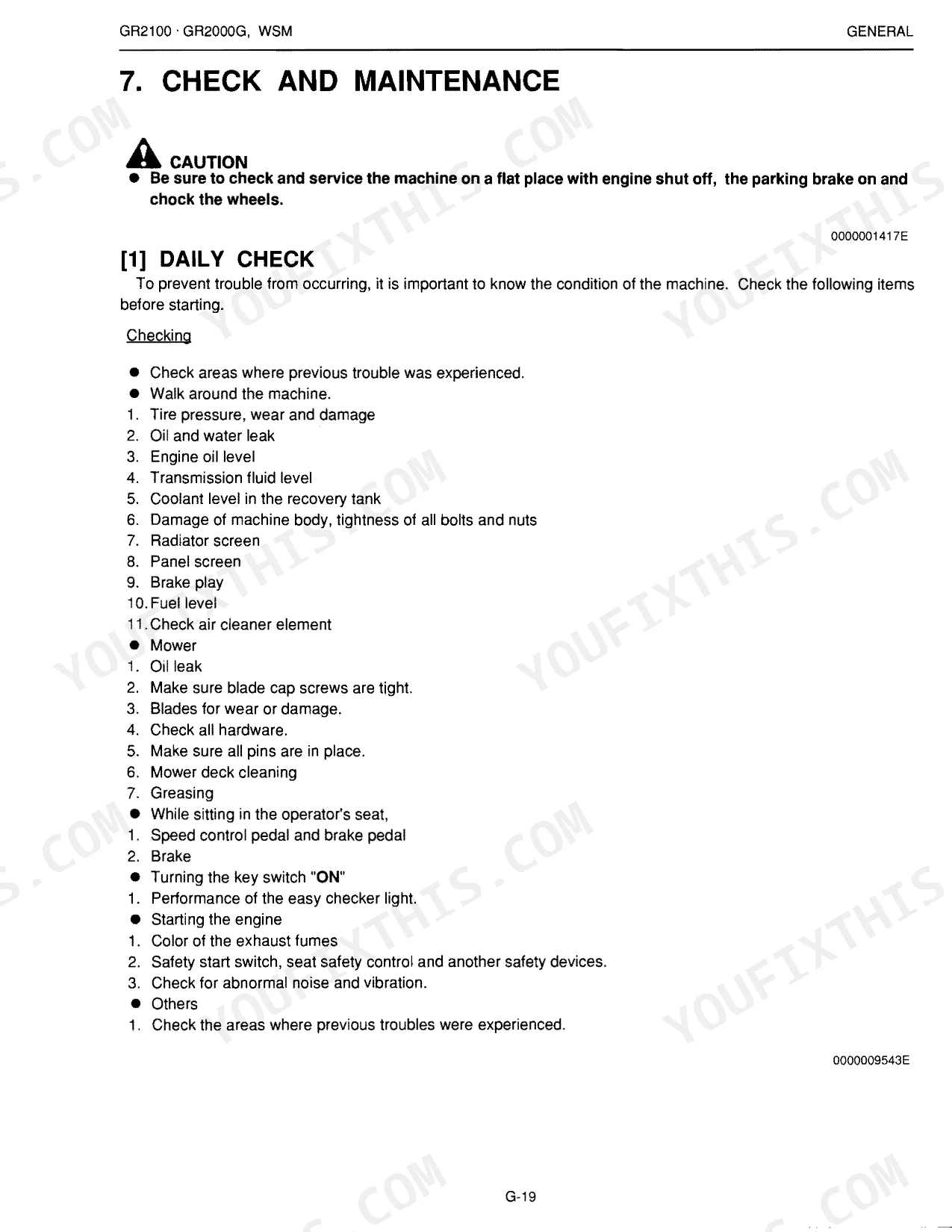
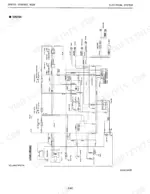
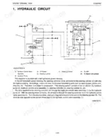
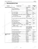
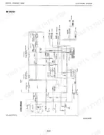
All 490 pages of the Kubota GR2100 / GR2000G Workshop Manual (OEM #0000010290E) are built around one purpose: factory-level service for your Kubota lawn tractor, engine to transaxle. Inside you get 9 pages of complete wiring diagrams covering starting, charging, lighting, and KRA (Kubota Reverse Awareness) circuits, plus 10 pages of hydraulic schematics mapping every line in the HST transmission, mower lift, and steering system. Add 20 pages of troubleshooting charts, 10 pages of torque tables, and 100 pages of disassembly and reassembly procedures across every major system. Torque the mower blade screw to 98-118 N·m; front wheel mounting screws go to 108.5-130.2 N·m. No more chasing specs across half a dozen forum threads. Bookmarked by section and keyword-searchable; open it on your phone in the shop and get to work.
What's Inside This Kubota GR2100, GR2000G Manual
| System | Pages | Key Topics |
|---|---|---|
| Safety Instructions | 5-12 | Safety First, Before Servicing And Repairing, Safety Starting, Safety Working, Avoid Fires, Ventilate Work Area, Prevent Acid Burns, Dispose of Fluids Properly |
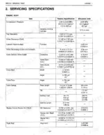
| Specifications | 13-14 | Specifications Table (Model, Engine, Capacities, Dimensions, Weight, Tires, Steering, Traveling System, PTO System), Mower Specifications (Model) |
| Dimensions | 15-18 | Overall Dimensions, Top View Dimensions, Side View Dimensions |
| General | 19-90 | Identification, General Precautions, Handling Precautions For Electrical Parts And Wiring, Lubricants, Fuel And Coolant, Tightening Torques, Maintenance Check List |
| Engine Body | 91-96 | Engine Body Mechanism, Lubricating System Mechanism, Cooling System Mechanism, Fuel System Mechanism |
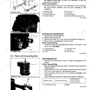
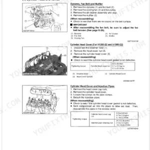
| Engine Servicing | 97-156 | Servicing Specifications, Tightening Torques, Checking, Disassembling And Servicing (Checking And Adjusting, Preparation, Disassembling And Assembling) |
| Engine 2 Servicing | 157-170 | Servicing Specifications (Engine Body, Lubricating System, Ignition System), Tightening Torques, Checking |
| Transaxle | 171-188 | Structure, Travelling System (Hydraulic Transmission, Glide Steer Section, Front Wheel Drive Section), Mower Pto System (Mower Pto Clutch), Others (Hydraulic Pump Section) |
| Transaxle Servicing | 189-232 | Serviving Specifications, Tightening Torques, Checking, Disassembling And Servicing (Checking And Adjusting, Preparation, Disassembling And Assembling) |
| Brakes | 233-244 | Servicing Specifications, Tightening Torques, Checking, Disassembling And Servicing (Checking And Adjusting, Disassembling And Assembling) |
| Front Axle | 245-248 | Structure (Front Axle Components), Power Transmission, Differential System |
| Front Axle Servicing | 249-266 | Servicing Specifications, Tightening Torques, Checking, Disassembling And Servicing (Checking And Adjusting, Preparation, Disassembling And Assembling) |
| Steering | 267-272 | Hydraulic Circuit Steering, Steering Controller, Steering Cylinder |
| Steering Servicing | 273-286 | Servicing Specifications, Tightening Torques, Checking, Disassembling And Servicing (Checking And Adjusting, Preparation, Disassembling And Assembling) |
| Hydraulic System | 287-298 | Hydraulic Circuit, Hydraulic Pump, Hydraulic Control Valve (Mower Lift Circuit, Hst Relief Valve), Mower Lift Cylinder, Mower Linkage |
| Hydraulic System Servicing | 299-310 | Servicing Specifications, Tightening Torques, Checking, Disassembling And Servicing (Checking And Adjusting, Preparation, Disassembling And Assembling) |
| Electrical System | 311-326 | Wiring Diagram, Starting System, Charging System, Lighting System, KRA (Kubota Reverse Awareness) System |
| Electrical System Servicing | 327-352 | Servicing Specifications, Tightening Torques, Checking, Disassembling And Servicing (Checking And Adjusting, Disassembling And Assembling) |
| Mower | 353-356 | Structure (Power Transmission), Lifting Mechanism (Lift Cylinder, Lift Link Shaft, Hydraulic Lift Lever, Lift Link, Rear Link) |
| Mower Servicing | 357-370 | Servicing Specifications, Tightening Torques, Checking, Disassembling And Assembling (Checking And Adjusting, Preparation, Servicing) |
| Safety And General Information | 371-382 | Safety Precautions, Engine Identification Numbers, Oil Recommendations, Fuel Recommendations, Periodic Maintenance Instructions, Carburetor and Intake Manifold, Connecting Rod |
| Special Tools | 383-386 | Some Special Tools for This Engine Are, Special Tools You Can Make, Flywheel Holding Tool, Rocker Arm/Crankshaft Tool, Cylinder Leakdown Tester, RTV Silicone Sealant |
| Troubleshooting | 387-392 | Troubleshooting Guide, Engine Cranks But Will Not Start, Engine Starts But Does Not Keep Running, Engine Starts Hard, Engine Will Not Crank, Engine Runs But Misses |
| Air Cleaner And Air Intake System | 393-398 | Air Cleaners, Precleaner Service, Paper Element Service, Air Cleaner Element Cover and Seal, Air Cleaner Base, Breather Tube, Air Cleaner Components |
| Lubrication System | 411-414 | Service, Oil Recommendations, Checking Oil Level, Changing Oil and Oil Filter, Oil Sentry ™, Installation, Testing |
| Electrical System And Components | 415-436 | Spark Plugs, Spark Plug Service, Inspection, Battery, Battery Size Recommendations, Battery Maintenance, Battery Test, Electronic CD Ignition Systems |
| Disassembly | 437-452 | Disconnect Spark Plug Leads, Shut Off Fuel Supply, Drain Oil From Crankcase and Remove Oil Filter, Remove Air Cleaner Assembly, Remove Fuel Pump, Remove Throttle and Choke Controls |
| Inspection And Reconditioning | 453-466 | Operation, Camshaft, Crankshaft, Procedure to Remove Crankshaft Plug, Procedure to Install New Plug, Crankcase, Honing, Clean Cylinder Bore After Honing |
| Reassembly | 467-490 | Install Flywheel End Oil Seal, Install Governor Cross Shaft, Install Crankshaft, Install Connecting Rods with Pistons and Rings, Install Camshaft, Determining Camshaft End Play |
Quick Reference Specifications
| Specification | Value | Page |
|---|---|---|
| All Models | ||
| Rear wheel mounting nut | 77.5 to 90.2 N·m (7.91 to 9.19 kgf·m, 57.2 to 66.5 ft-lbs) | p. 195 |
| Front wheel mounting screw | 108.5 to 130.2 N·m (11.07 to 13.29 kgf·m, 80 to 96 ft-lbs) | p. 253 |
| Mower blade screw | 98 to 118 N·m (10.0 to 12.0 kgf·m, 72.3 to 86.8 ft-lbs) | p. 361 |
| Gear box mounting screw (for aluminum gear case) | 39.2 to 44.1 N·m (4.0 to 4.5 kgf·m, 28.9 to 32.5 ft-lbs) | p. 361 |
| Fuse capacity (E/G STOP) | 15 A | p. 73 |
| Fuse capacity (IG/M) | 10 A | p. 73 |
| Mower blade screw torque | 98 to 118 N·m (10.0 to 12.0 kgf·m, 72.3 to 86.8 ft-lbs) | p. 366 |
| Left Tip of Blade to Right Tip of Blade (Difference Allowable Limit) | Less than 3 mm (0.12 in.) | p. 360 |
| Mower belt replacement | Replace | p. 76 |
| GR2100 | ||
| Battery (GR2100) | 12 V, 450CCA | p. 13 |
| Fan drive belt tension (Deflection) | 7 to 9 mm (0.28 to 0.35 in.) | p. 106 |
| GR2000G | ||
| Battery (GR2000G) | 12 V, 285CCA | p. 13 |
Kubota GR2100, GR2000G Common Problems This Manual Covers
Kubota GR2100 engine turns over freely but will not fire or start
Check fuel level (18 L tank capacity) and confirm the shutoff valve is open. Bleed air from fuel lines and inspect the filter for clogs. Measure battery voltage at the terminals: it must read more than 12 V (page 334). Check fuses at page 73: slow-blow main is 40 A, IG/M is 10 A. Confirm brake and seat switches are engaged.
Manual Section: Engine Does Not StartAll electrical equipment suddenly dead, or engine won't crank after sitting overnight p. 327
Inspect all wiring connectors for corrosion and loose pins; this is where most intermittent failures hide. Test battery voltage at the terminals: a fully charged battery reads 12.6 V (page 56); below 12.0 V means it is nearly discharged. Check the 40 A slow-blow fuse and the 3 A OPC fuse at page 73. Clean and retighten both battery cables.
Manual Section: Electrical System - Battery/StartingHydrostatic drive won't move tractor at all, or only in one direction p. 189
Check the transmission fluid level first: total capacity is 3.3 L, top up if low. Inspect the transaxle case for external leaks. If the tractor moves in one direction only, work through hydraulic transmission diagnostics beginning on page 189. Verify the neutral return mechanism isn't stuck and look for aerated or milky oil, which signals contamination.
Manual Section: Hydrostatic Transmission IssuesMower deck leaves uneven strips or blades won't reach full cutting speed p. 357
Inspect blade condition and measure balance: left-to-right tip difference must be less than 3 mm (page 360). Replace any blade showing deep nicks or bends. Torque blade screws to 98 to 118 N·m (page 366). Check the mower belt for cracking or glazing at page 76 and replace if worn. Clean packed grass from under the deck before reassembly.
Manual Section: Mower IssuesBrake pedal soft or spongy, tractor rolls past its intended stopping point p. 233
Test brake pedal free travel before touching any adjustment: factory spec is 15 to 25 mm (page 59). If travel exceeds 25 mm, adjust the brake rod linkage in the Brakes section starting on page 233. Inspect pads for wear and verify the parking brake holds the tractor stationary on a grade. Check that all brake hardware is torqued correctly.
Manual Section: Brakes IssuesFrequently Asked Questions
How do I remove the mower deck on a Kubota GR2100?
To remove the mower deck, first turn the front wheel to the right. Then, pull out the mower deck to the left. For more detailed instructions, refer to page 9-S6 in the manual.
What are the common transmission problems on a Kubota GR2100?
Common transmission problems include the system not operating in either direction, vibration and noise, loss of power, oil overheating, the machine not stopping in neutral, or operating only in one direction. Specific causes can range from a clogged oil filter cartridge to a defective HST relief valve or hydraulic pump. For example, if there is a loss of power due to a clogged oil filter cartridge, the solution is to replace it.
Why does my Kubota GR2000G have glide steer or axle issues?
Glide steer or axle issues on a Kubota GR2000G can manifest as front wheels wandering to the right or left, or front wheels not being driven. Causes for wandering include improper toe-in adjustment (page 5-S4), a loose tie-rod end (page 5-S10), or air sucked into the power steering circuit. If front wheels are not driven, it could be due to broken front wheel driving gears in the front axle gear case (page 5-S10), a broken universal joint (page 5-S8), or a broken front differential gear (page 5-S12,13).
How do I check axle seals and bushings on a GR2100?
To check axle seals and bushings, inspect the oil seals for damage and the bushings for wear. If any oil seals or bushings are found to be worn or damaged, they must be replaced. This procedure is outlined in the 'Bushing and Oil Seal' section of the manual.
What do I get after purchasing this Kubota GR2100, GR2000G manual?
This is a 490-page searchable PDF ready for immediate download. Works on any device — pull it up on your phone while you're under the hood. No shipping, no waiting.
Can I print this Kubota GR2100, GR2000G manual?
None at all — the PDF is DRM-free. Print whatever sections you need to take out to the shop. Standard letter or A4 paper works.
Are electrical wiring diagrams included in this Kubota GR2100, GR2000G manual?
Complete wiring diagrams are included, covering all electrical circuits, harness routing, and connector pinouts for the Kubota GR2100, GR2000G.
Document Quality
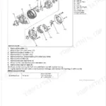
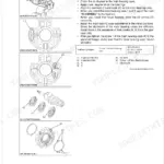
This document is a scanned PDF with an OCR layer, enabling you to search and copy text. The text quality is generally clear and readable, although some smaller labels within diagrams might appear less crisp. Diagrams and illustrations are primarily raster images or scanned photos, meaning they may not maintain sharpness when highly zoomed. Pages are mostly clean with minimal scan artifacts, and you will encounter several blank pages interspersed throughout.


Reviews
There are no reviews yet.