




This Kubota Workshop Manual is the factory service reference for the B2410, B2710, and B2910 compact tractors, powered by the D1105 and V1505 Kubota diesel engines. Its 381 pages take the tractor apart system by system for repair-level work.
Coverage runs from the General section and full engine teardown through the clutch, transmission and hydrostatic drive, rear axle, brakes, front axle, power steering, hydraulic system, and the complete electrical system. Each system carries features, structure, servicing specifications, tightening torques, and checking and disassembly procedures, and the electrical section includes the wiring diagram and starting circuit.
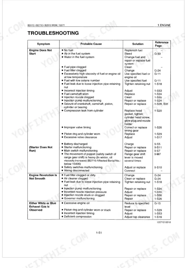
Owners, restorers, and independent mechanics can use it to diagnose drive and hydraulic faults, set head bolt and wheel torques, service the front axle and steering, and trace electrical problems. It downloads as a PDF you can read on any device and print at the bench.
Complete the set for your B2410, B2710, B2910
- Operator Manual: Kubota B2410 Operator Manual
- Operator Manual: Kubota B2710, B2910, B7800 Tractor Operator Manual
Other editions of this manual
What's Inside This Manual
| System | Pages | Key Topics |
|---|---|---|
| General | 11-65 | Tractor Identification, Model Name and Engine Serial Number, Cylinder Number, E2 Engine |
| Engine | 66-145 | Engine Body (Cylinder Block, Cylinder Head, Crankshaft, Piston and Piston Rings, Connecting Rod, Camshaft, Fuel Camshaft, Rocker Arm, Intake and Exhaust Valve, Valve Timing, Flywheel, Air Cleaner, Muffler) |
| Clutch | 146-162 | Linkage Mechanism, Operation |
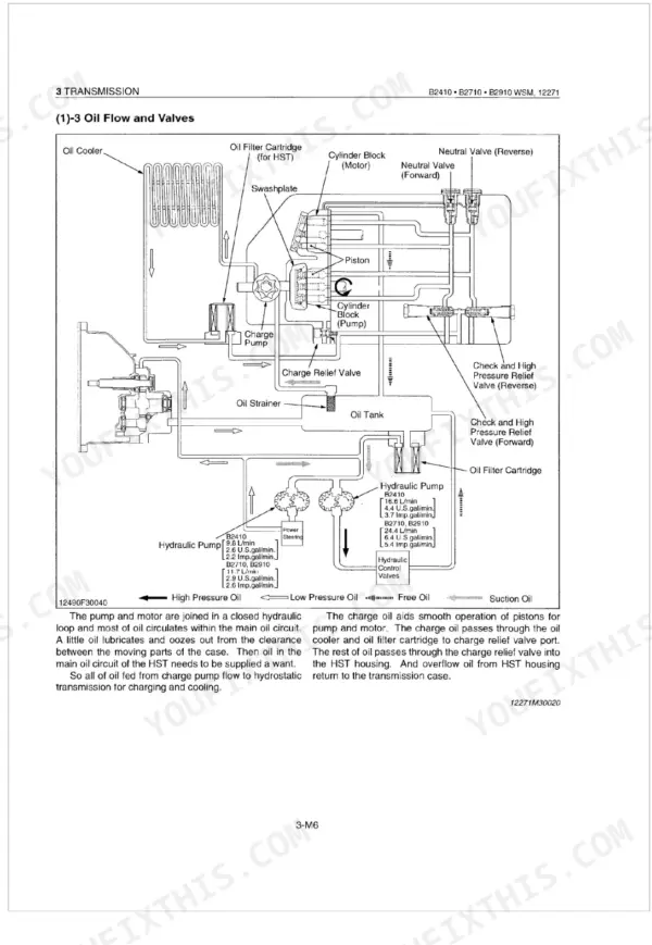
| Transmission | 163-219 | Structure (B2410, B2710 B2910), Travelling System (Hydrostatic Transmission, Hi-Lo Gear Shift Section, Range Gear Shift Section, Front Wheel Drive Section) |
| Rear Axle | 220-229 | Features, Separating Rear Axle Case, Draining Transmission Fluid, Rear Wheels (B2410 Only), Rear Wheels (B2710, B2910), Rear Axle Case (Bi-Speed Turn Type Only), Disassembling Rear Axle Case |
| Brakes | 230-241 | Features, Operation, During Braking, Brake Pedal, Adjusting Brake Pedal Free Travel, Separating Brake Pedal, Separating Rear Axle Case with Brake Assembly, Draining Transmission Fluid |
| Front Axle | 242-281 | Front Wheel Alignment (Wheel Drive Model, Bi-Speed Turn Type), Bi-Speed Turn Power Train (Standard 4WD, Bi-Speed Turn 4WD) |
| Steering | 282-304 | Hydraulic Pump, Hydraulic Circuit for Power Steering System, Power Steering Body, Oil Flow |
| Hydraulic System | 305-330 | Hydraulic Circuit, Hydraulic Pump, Hydraulic Block Type Outlet, Relief Valve, Position Control Valve, Feedback Linkage for Position Control, Hydraulic Cylinder |
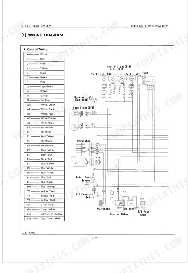
| Electrical System | 331-381 | Wiring Diagram, Electrical Circuit, Starting System (Starter, Glow Plug, Safety Switch), Engine Key Switch Shut-Off System (Engine Stop Solenoid) |
Quick Reference Specifications
| Specification | Value | Page |
|---|---|---|
| All Models | ||
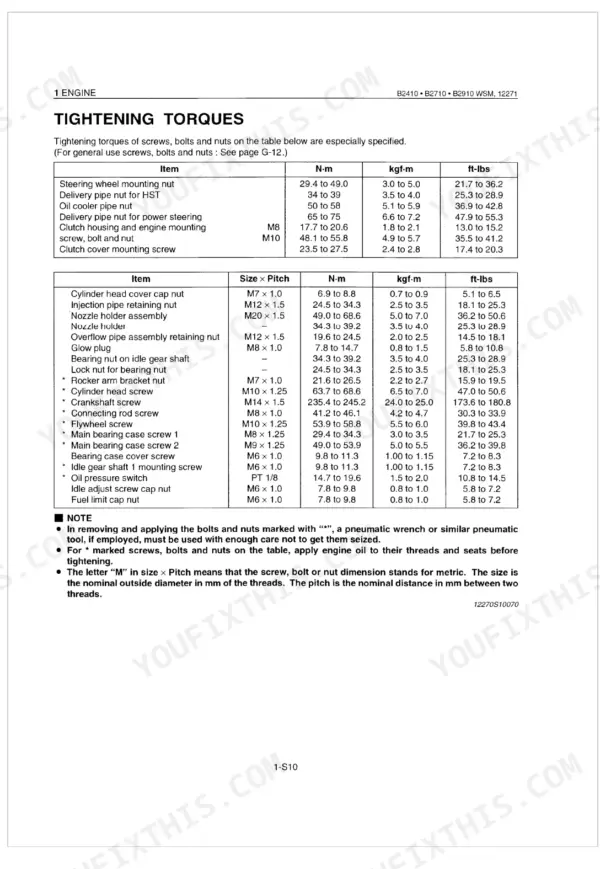
| Cylinder head screw torque (M10 x 1.25) | 63.7 to 68.6 N-m (6.5 to 7.0 kgf-m, 47.0 to 50.6 ft-lbs) | p. 99 |
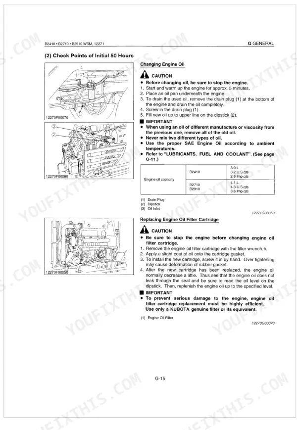
| Hydraulic oil filter replacement interval | Replace every 200 hours | p. 26 |
| Fuel filter element replacement interval | Replace every 200 hours | p. 26 |
| Air cleaner element (primary) replacement interval | Replace every 200 hours | p. 26 |
| Fan belt deflection | 7 to 9 mm (0.28 to 0.35 in.) | p. 39 |
| Starter Commutator O.D. (Allowable Limit) | 27.0 mm (1.063 in.) | p. 360 |
| Starter M terminal nut torque | 8.8 to 11.8 N-m (0.9 to 1.2 kgf-m, 6.5 to 8.7 ft-lbs) | p. 360 |
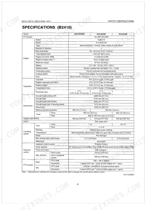
| Battery | 12 V, RC: 79 min, CCA: 433 A | p. 7 |
| Battery voltage (Factory spec) | More than 12 V | p. 361 |
| Relief Valve Setting Pressure | 13.2 to 13.7 MPa (135 to 140 kgf/cm², 1920 to 1991 psi) | p. 318 |
| B2410 | ||
| Transmission case capacity, B2410 | 12.5 L (3.30 U.S.gals, 2.75 Imp.gals) | p. 24 |
| B2710 Affected Serial No.: below 15496 | ||
| Transmission case capacity, B2710 Affected Serial No.: below 15496 | 14.0 L (3.70 U.S.gals, 3.08 Imp.gals) | p. 24 |


