
This is the Kubota workshop manual for the B2410, B2710, and B2910 tractors, with a dedicated B7800 HSD supplement, supplied as a 426-page PDF download. It documents the D1105-E-D16, V1305-E-D12, and V1505-E-D16 diesel engines and the hydrostatic drive used on these compact tractors.
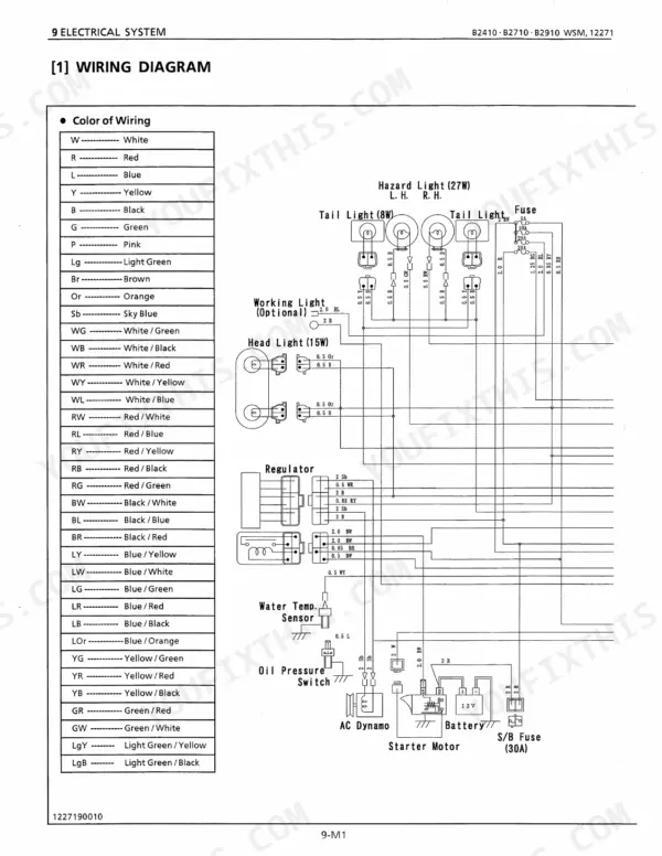
Organized by system, it takes you through the engine, clutch, transmission, rear axle, brakes, front axle, steering, hydraulic system, and the electrical system with wiring diagrams. Each part is split into mechanism and servicing, so you get the theory of operation followed by the disassembly, inspection limits, and reassembly steps.
This is the manual for real repair work: torque values, service intervals, factory specifications, and step-by-step procedures for owners and independent mechanics who service these Kubota tractors themselves.
Complete the set for your B2410–B7800 Series
- Parts Catalog: Kubota B7800HSD Tractor Parts Catalog
- Operator Manual: Kubota B2410 Operator Manual
- Operator Manual: Kubota B2710, B2910, B7800 Tractor Operator Manual
Other editions of this manual
- Kubota B1710, B2110, B2410, B2710 Tractor Shop Manual (incl. Wiring) Original price was: $61.99.$39.99Current price is: $39.99.
- Kubota B2410, B2710, B2910 Workshop Manual — Wiring Diagrams Original price was: $65.99.$39.99Current price is: $39.99.
What's Inside This Kubota B2410–B7800 Series Manual
| System | Pages | Key Topics |
|---|---|---|
| Specifications | Model B7800HSD | |
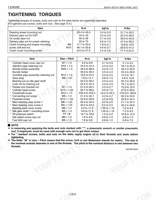
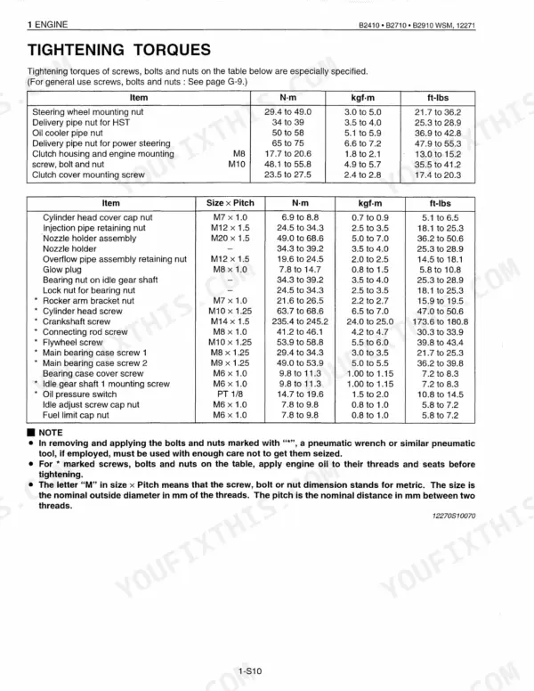
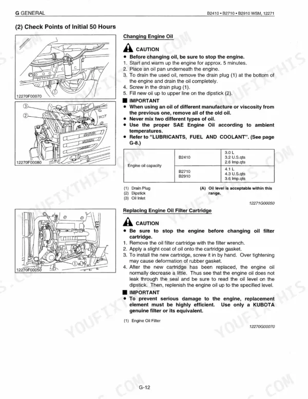
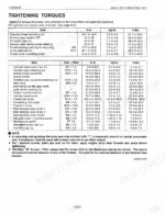
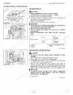
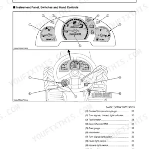
| General | Features, Tractor Identification, Handling Precautions for Electrical Parts and Wiring, Lubricants, Fuel and Coolant, Tightening Torques, Maintenance, Check and Maintenance | |
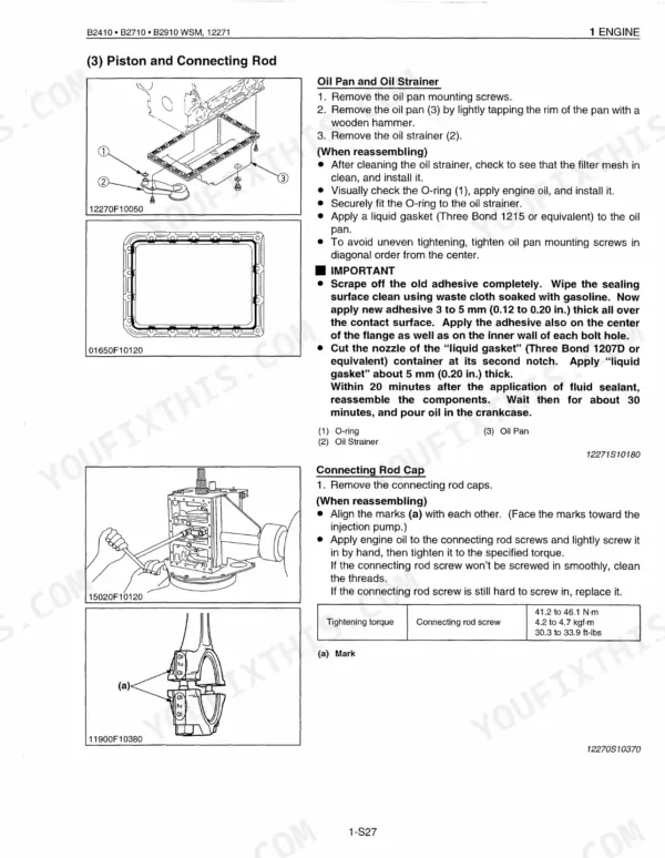
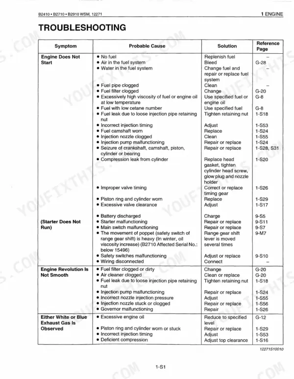
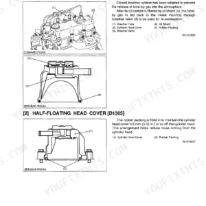
| Engine | Cylinder Block, Cylinder Head, Crankshaft, Piston and Piston Rings, Lubricating System, Fuel System | |
| Clutch | Clutch Disc, Pressure Plate Assembly, Release Bearing, Release Fork, Clutch Pedal, Clutch Shaft | |
| Transmission | Hydrostatic Transmission, PTO System, Differential Gear System, Hi-Lo Gear Shift Section, Range Gear Shift Section, Front Wheel Drive Section | |
| Rear Axle | Differential Gear Shaft, Rear Axle Case, Differential Gear, Spiral Bevel Gear | |
| Brakes | Brake Pedal, Parking Brake Lever, Brake Disc, Friction Plate, Cam Plate, Brake Shaft | |
| Front Axle | 2 Wheel Drive Model, 4 Wheel Drive Model, Bi-Speed Turn Type, Front Wheel Alignment, Knuckle Shaft, Front Axle Case | |
| Steering | Hydraulic Pump, Power Steering Body, Hydraulic Circuit, Control Valve, Sector Gear Shaft, Rack (Piston) | |
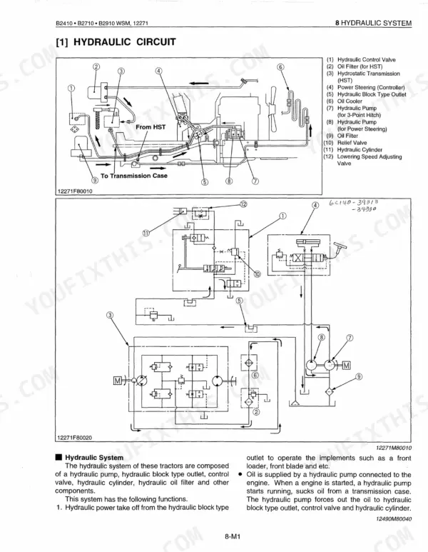
| Hydraulic System | Hydraulic Circuit, Hydraulic Pump, Hydraulic Block Type Outlet, Relief Valve, Position Control Valve, Hydraulic Cylinder | |
| Electrical System | Wiring Diagram, Starting System, Engine Key Switch Shut-Off System, Charging System, Lighting System, Easy Checker | |
| B7800 Hsd(Supplement) | Control Valve (Quarter Inching Valve), Relief Valve, Feedback Linkage, Hydraulic Cylinder, Wiring Diagram, Operators Presence Control (Opc) |
Quick Reference Specifications
| Specification | Value | Page |
|---|---|---|
| General Use Screws, Bolts and Nuts (M6, No-grade or 4T) | 7.85 to 9.31 N·m (0.80 to 0.95 kgf·m, 5.79 to 6.87 ft-lbs) | p. 24 |
| Rear wheel mounting screw and nut | 108 to 125 N·m (11.0 to 12.8 kgf·m, 80 to 93 ft-lbs) | p. 224 |
| Front wheel mounting nut (4WD) | 77.5 to 90.1 N·m (7.9 to 9.2 kgf·m, 57.1 to 66.5 ft-lbs) | p. 258 |
| Hydraulic oil filter (for HST) replacement interval | Every 200 Hours | p. 25 |
| Engine oil filter replacement interval | Every 200 Hours | p. 25 |
| Fuel filter element replacement interval | Every 400 Hours | p. 25 |
| Fuel filter element cleaning interval | Every 200 Hours | p. 25 |
| Air cleaner element cleaning interval (Primary) | Every 50 Hours | p. 25 |
| Air cleaner element replacement interval (Primary and Secondary) | Every 1 year or every 6 times of cleaning | p. 25 |
| Fan Belt Tension (deflection) | 7 to 9 mm (0.28 to 0.35 in.) deflection at 98 N (10 kgf, 22 lbs) of force | p. 93 |
| Radiator screen maintenance | Check and clean | p. 26 |
| Transmission oil strainer cleaning interval | Every 200 Hours | p. 25 |
Kubota B2410–B7800 Series Common Problems This Manual Covers
3-point hitch lifts weak or slowly
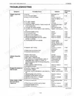
A lift that is slow or stops working under load usually traces to low fluid, a clogged filter, a worn pump, or internal leakage in the valves and cylinder. The hydraulic system section covers the circuit, pump, relief valve, position control valve, and hydraulic cylinder.
Manual Section: Hydraulic System p. 308HST loses drive or feels weak
An HST tractor that will not move or has weak forward and reverse response points to fluid or filter problems or wear in the hydrostatic unit. The transmission section documents the hydrostatic transmission along with the range and Hi-Lo gear shift sections.
Manual Section: Transmission p. 160Engine overheats during heavy work
Overheating while mowing or working hard is often a restricted radiator screen, dirty fins, a weak fan belt, or low coolant. The engine section covers the cooling and lubricating systems and the fan belt tension of 7 to 9 mm deflection.
Manual Section: Engine p. 64Will not start despite good battery
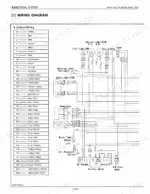
A no-start with a charged battery frequently comes down to a safety switch, the key shut-off system, or wiring in the start circuit. The electrical system section covers the starting system, the engine key switch shut-off system, and the wiring diagram.
Manual Section: Electrical System p. 334PTO will not engage or slips
A PTO that fails to engage or slips under load can be a clutch adjustment, linkage, or worn clutch components. The clutch section covers the clutch disc, pressure plate assembly, release bearing, release fork, and pedal adjustment.
Manual Section: Clutch p. 142Steering feels heavy or jerky
Heavy or jerky steering usually means low hydraulic oil, air in the system, or a worn pump or control valve. The steering section covers the hydraulic pump, power steering body, hydraulic circuit, and control valve.
Manual Section: Steering p. 284Frequently Asked Questions
Which models does this workshop manual cover?
It covers the Kubota B2410, B2710, and B2910 tractors, and includes a separate B7800 HSD supplement at the back for that model's specific hydraulic and electrical differences.
Does it include tightening torque specifications?
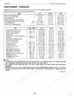
Yes. The general section covers lubricants, fuel, coolant, and tightening torques, and each system chapter lists its own factory torque values for that assembly. p. 14
What is the fan belt tension specification?
The engine section specifies a fan belt deflection of 7 to 9 mm (0.28 to 0.35 in.) at 98 N (10 kgf, 22 lbs) of applied force for all models. p. 64
Are wiring diagrams included?
Yes. The electrical system section contains the wiring diagram along with the starting, charging, and lighting systems and the Easy Checker. p. 334
What do I get after purchasing this Kubota B2410–B7800 Series manual?
A 426-page Workshop Manual in searchable PDF format, available the moment you finish checkout. View it on computer, tablet, or phone, with no shipping wait.
Am I free to print this Kubota B2410–B7800 Series Workshop Manual?
Yes. Print the sections you need to take out to the shop for your own use. Standard letter or A4 paper works.
Does this Kubota B2410–B7800 Series manual include hydraulic schematics?
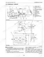
Full hydraulic system diagrams are included, covering circuits, valve locations, and hydraulic component specs for the Kubota B2410, B7800.



Reviews
There are no reviews yet.