

This is the Kubota service manual for the B2320, B2620, and B2920 compact tractors, supplied as a 406-page PDF download. It covers both the hydrostatic and manual transmission versions and the D1005-E3-D22, D1105-E3-D22, and D1305-E3-D22 diesel engines used across the range.
The manual is built around the machine's systems: engine, clutch, transmission, rear axle, brakes, front axle, steering, hydraulics, and electrical, with the general section holding tractor identification, lubricants and coolant, tightening torques, and the full maintenance check list. Wiring handling and the safety start circuit are documented in the electrical section.
Use it for real diagnosis and repair: torque tables, service intervals, safety switch values, and step-by-step procedures for owners and mechanics who service these Kubota tractors on their own.
What's Inside This Manual
| System | Pages | Key Topics |
|---|---|---|
| Intro | Safety First, Before Servicing And Repairing, Safety Starting, Safety Working, Avoid Fires, Ventilate Work Area, Prevent Acid Burns, Dispose Of Fluids Properly, Prepare For Emergencies, Safety Decals | |
| General | Tractor Identification (Model Name and Serial Number, Cylinder Number), Handling Precautions for Electrical Parts and Wiring (Battery, Fuse, Connector, Handling of Circuit Tester) | |
| Sect 1 Engine | Engine Body (Closed Breather, Half-Floating Head Cover, Governor, Half-Floating Head Cover [D1305], Three Lever Type Fork Lever, At Rated Operation, Overloaded Operation) | |
| Sect 2 Clutch | Linkage Mechanism | |
| Sect 3 Transmission | Structure (Hydrostatic Transmission Type, Manual Transmission Type) | |
| Sect 4 Rear Axle | Structure | |
| Sect 5 Brakes | Linkage, Operation (During Braking) | |
| Sect 6 Front Axle | Structure | |
| Sect 7 Steering | Structure (Steering Linkage, Power Steering, Manual Transmission Type, Hydrostatic Transmission Type) | |
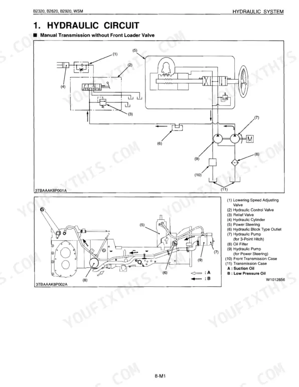
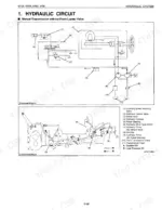
| Sect 8 Hydraulic | Hydraulic Circuit, Hydraulic Pump, Control Valve Assembly (Structure, Operation), Three Point Hydraulic System (Feedback Linkage, Control Valve, Relief Valve, Hydraulic Cylinder) | |
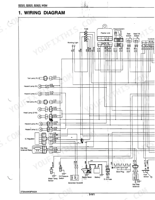
| Sect 9 Electrical | Wiring Diagram, Engine Starting System and Stopping System (Opc System Circuit, Controller, Safety Switch and Engine Condition) |
Quick Reference Specifications
| Specification | Value | Page |
|---|---|---|
| All Models | ||
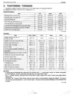
| Joint bolt (Front loader pipe) torque | 48 to 56 N·m (4.9 to 5.7 kgf·m, 36 to 41 lbf·ft) | p. 210 |
| Rear wheel mounting nut torque | 145 to 150 N·m (14.8 to 15.3 kgf·m, 107 to 111 lbf·ft) | p. 194 |
| Seat switch resistance (Operator on the seat) | 0 Ω | p. 387 |
| PTO Switch 1 resistance (PTO gear shift lever in "NEUTRAL" position) | 0 Ω | p. 392 |
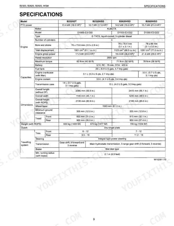
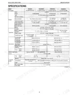
| Min. Turning Radius (with brake) | 2.1 m | p. 9 |
| Max. Lift Force (At lift points) | 615 kg | p. 10 |
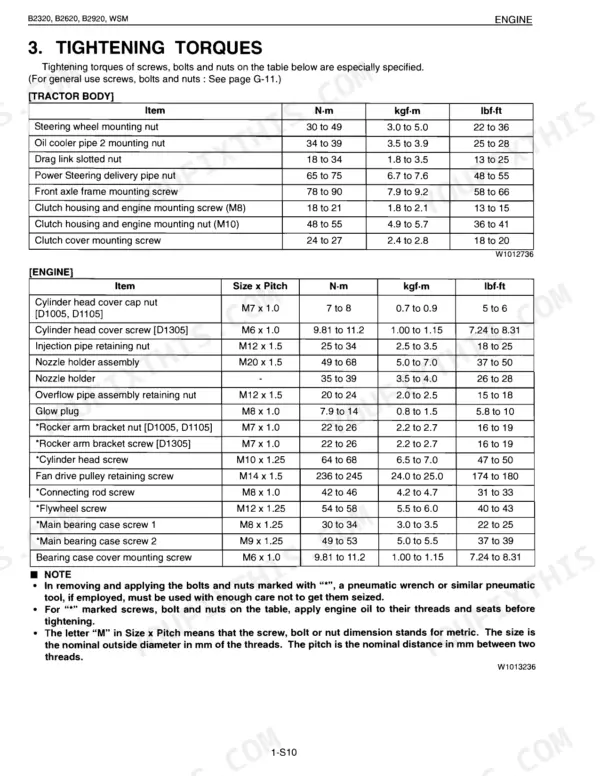
| General Use Bolt Torque (M10, Property class 8.8) | 48 to 55 N·m | p. 26 |
| B2320, B2620, B2920 (Manual Transmission Models) | ||
| Main Shift Switch resistance (Main gear shift lever in "NEUTRAL" position) | 0 Ω | p. 391 |
| B2320HSD, B2620HSD, B2920HSD (HST Models) | ||
| HST safety switch length A | 17.3 to 17.7 mm (0.682 to 0.696 in.) | p. 390 |
| B2320DT, B2620HSD | ||
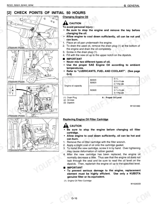
| Engine Crankcase Capacity (with filter) | 3.1 L | p. 9 |
| B2320DT | ||
| Transmission Case Capacity | 14 L | p. 9 |
| B2320 | ||
| Overall Length (without 3P) | 2385 mm | p. 9 |
