
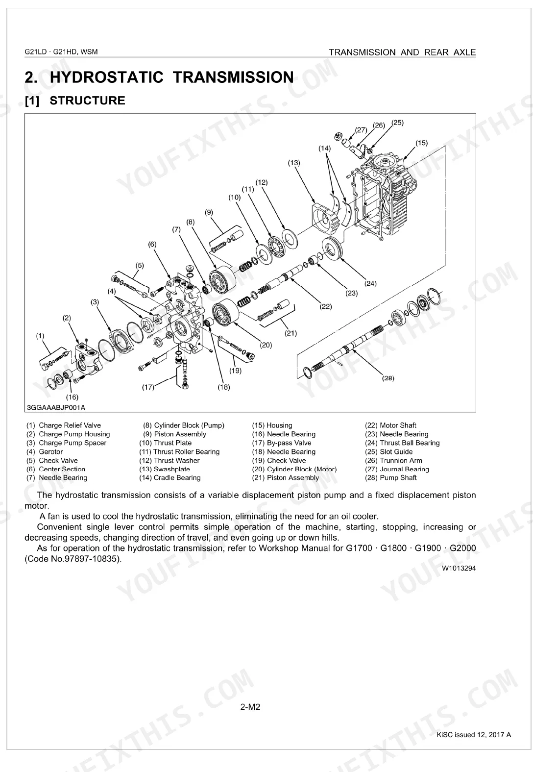
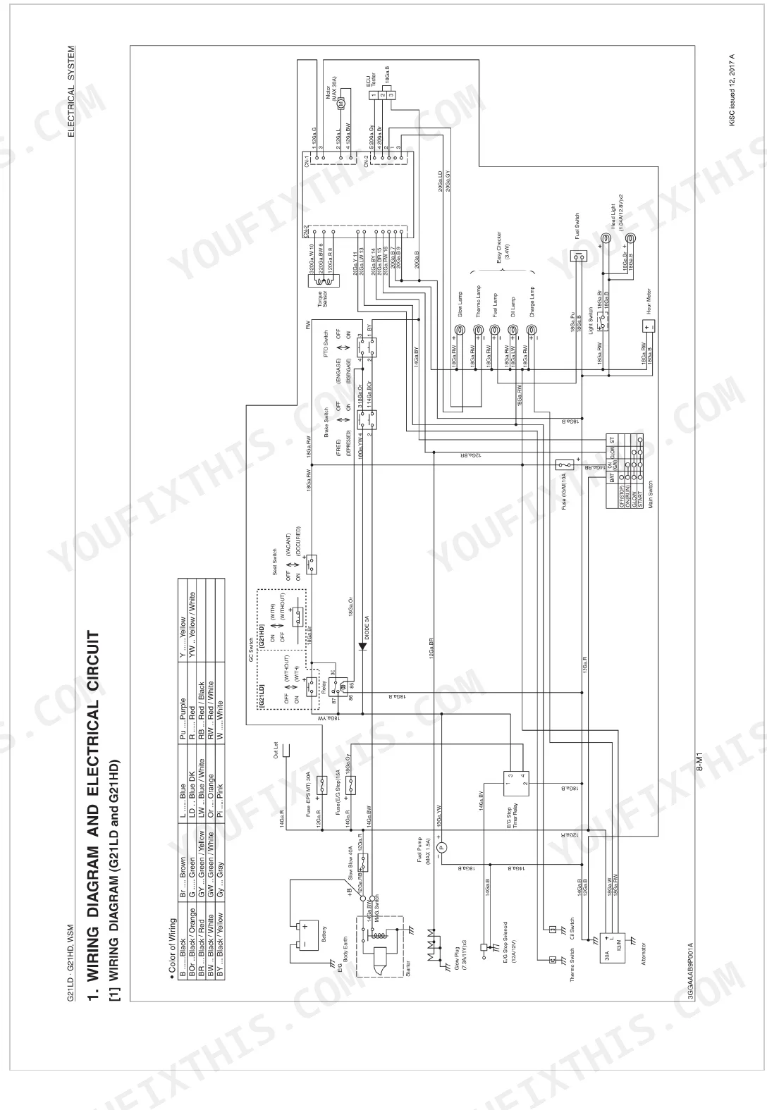
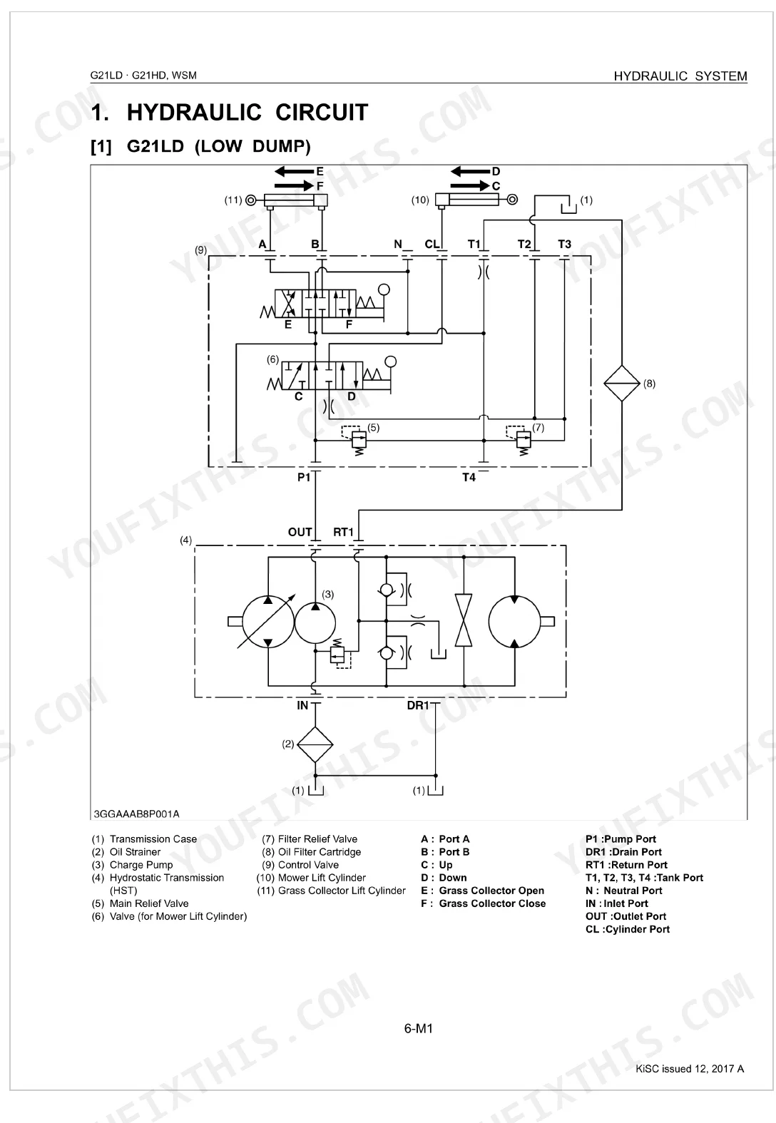
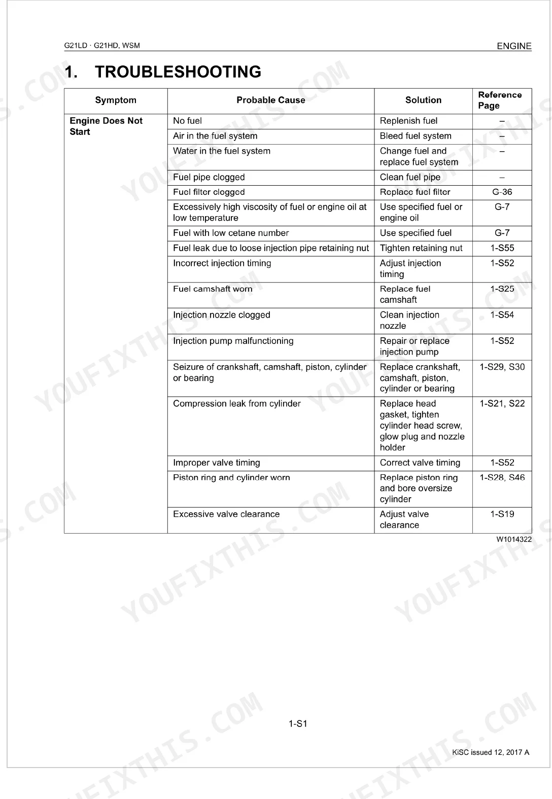
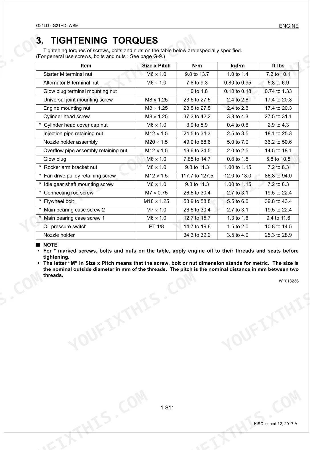
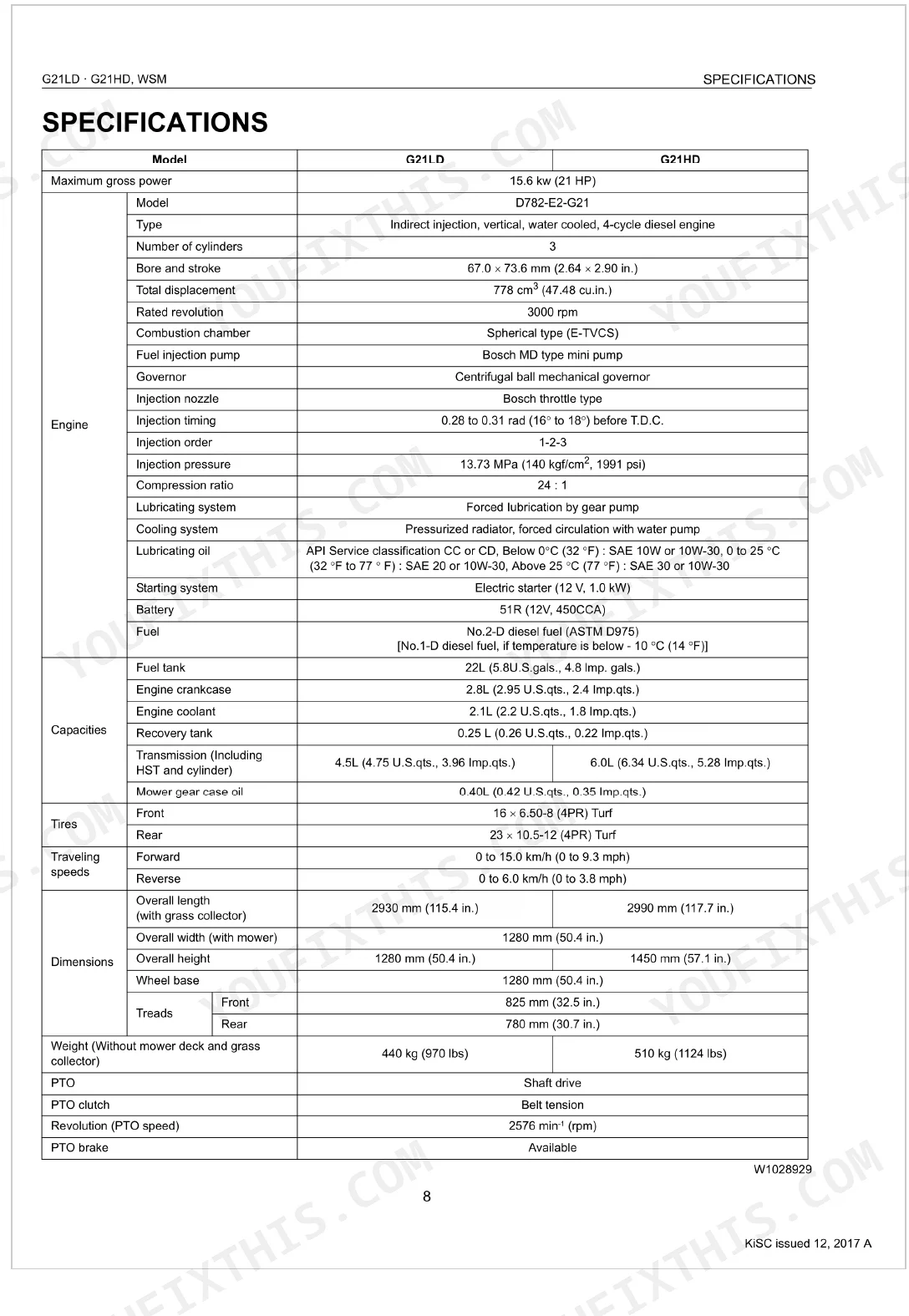
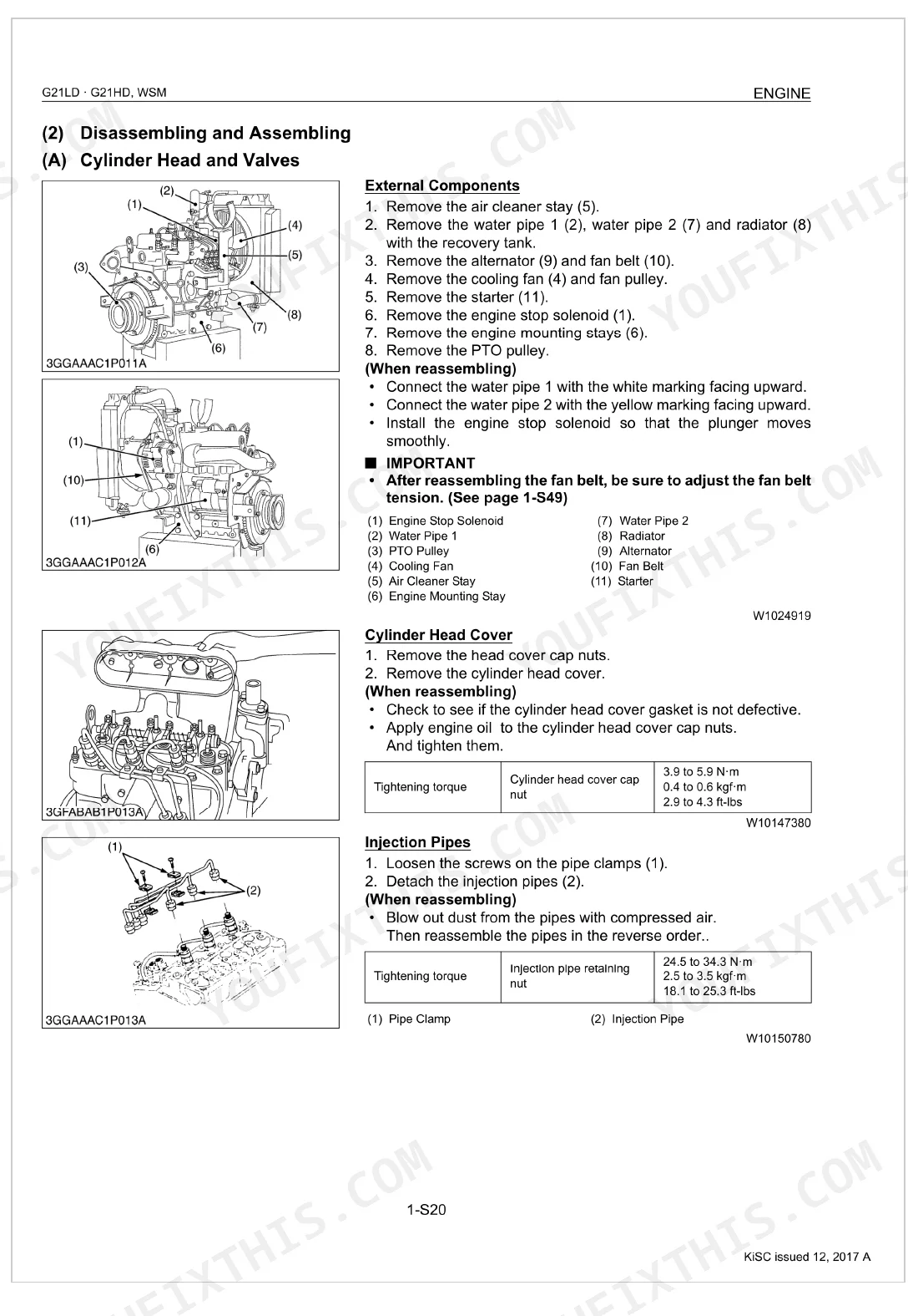
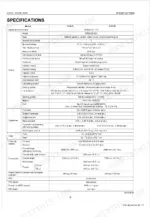
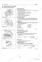
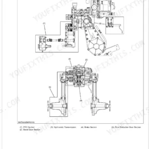
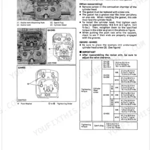
Kubota built the Low Dump and High Dump versions of this machine with enough mechanical difference to matter, and this 330-page Workshop Manual (OEM #9Y011-15092) covers both. Step-by-step procedures walk through disassembly, reassembly, and adjustment on every major assembly, while troubleshooting tables sort faults across the engine, HST transmission, brakes, PTO, and electrical system. For diagnosis there are hydraulic schematics (mower lift, grass collector cylinder, auxiliary control valve, EPS-assisted steering), exploded views, and a wiring diagram drawn for both the G21LD and G21HD. Specs sit where you need them: torque the center pulley holder mounting screw to 77.4-90.2 N·m, set the side blade pulley holder nut to 102.9-117.6 N·m, and hold belt retainer clearance at 2.0 mm. Search any value by keyword and get back to work.
What's Inside This Kubota G21LD, G21HD Manual
| System | Pages | Key Topics |
|---|---|---|
| Safety First | 4-10 | - |
| General | 15-72 | Identification, Wiring, Battery, Fuse, Connector, Handling of Circuit Tester, Lubricants, Fuel and Coolant |
| Engine | 73-129 | Engine Body, Lubricating System, Cooling System, Fuel System, Checking, Disassembling and Servicing, Separating Engine |
| Transmission and Rear Axle | 130-162 | Hydrostatic Transmission, Oil Flow, By-Pass Valve, Charge Pump, Checking, Disassembling and Servicing |
| Brakes | 163-174 | Parking Brake, Pedal System, Brake Assembly, Brake Lining, Brake Drum |
| Front Axle | 175-183 | Front Axle Support, Tie-rod, Knuckle Arm, Kingpin, PTO brake |
| Steering | 184-220 | System Configuration, Construction and Function of Main Components, Power Steering Assembly, EPS Controller, Troubleshooting Based on Each Symptom, Troubleshooting Based on Error Code, Checking, Disassembling and Servicing |
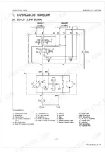
| Hydraulic System | 221-259 | Hydraulic Circuit, G21LD (Low Dump), G21HD (High Dump), Relief Valve (G21LD, G21HD), Mower Lifting Circuit (G21LD, Neutral, Down |
| PTO System | 260-268 | PTO clutch spring, front PTO belt, PTO brake, PTO shaft, tension arm, PTO pulley |
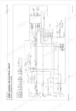
| Electrical System | 269-299 | Wiring Diagram and Electrical Circuit, Wiring Diagram (G21LD and G21HD), Electrical Circuit (G21LD and G21HD), Checking, Disassembling and Servicing, Battery, Starting System, Engine Key Switch Shut-Off System |
| Mower | 300-316 | Mower Blade, Mower Belts, Gear Case, Center Pulley Holder, Side Blade Pulley Holder |
| High Dump Grass Collector | 317-330 | Checking, Disassembling and Servicing, Disassembling Grass Collector Bag, Platform Complete, Lift Arm Assembly and Head Guard |
Every system also includes checking, disassembling and servicing, servicing specifications, tightening torques, and troubleshooting.
Quick Reference Specifications
| Specification | Value | Page |
|---|---|---|
| Belt Retainer to Front PTO Belt Clearance | 2.0 mm | p. 303 |
| Tension Collar to Tension Arm Bushing Clearance (Factory spec) | 0.002 to 0.114 mm | p. 303 |
| Center pulley holder mounting screw | 77.4 to 90.2 N·m | p. 304 |
| Side blade pulley holder mounting nut and bolt | 102.9 to 117.6 N·m | p. 304 |
| Front Tip of Blade to Rear Tip of Blade Difference (Allowable Limit) | Less than 5 mm | p. 303 |
| Left Tip of Blade to Right Tip of Blade Difference (Allowable Limit) | Less than 4 mm | p. 303 |
| Charge Relief Valve Setting pressure | 0.32 to 0.41 MPa | p. 139 |
| Transmission Fluid (Including HST and Cylinder) Capacity | 4.5 L | p. 139 |
| Fuel filter replacement frequency | Every 500 Hrs | p. 27 |
| Fuel tank capacity | 22 L (5.8 U.S.gal.) | p. 31 |
| Intake air line check frequency | Every 200 Hr | p. 27 |
| Air cleaner element cleaning frequency | Every 50 Hrs | p. 27 |
Kubota G21LD, G21HD Common Problems This Manual Covers
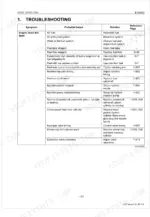
Weak forward or reverse movement under load, building toward complete hydrostatic drive loss
Drain the transmission fluid and pull the oil strainer for inspection. Check the charge relief valve setting against page 139, then adjust it to hold 0.32 to 0.41 MPa. Refill the G21LD with exactly 4.5 L of fluid.
Manual Section: Transmission and Rear Axle TroubleshootingEngine overheating, rapid coolant loss, and severe loss of power during continuous mowing
Inspect the cooling system for leaks, then pressure-test the radiator cap. It should hold 88 ~ 98 kPa as specified on page 83. If pressure bleeds off in under 10 seconds, replace the cap.
Manual Section: Engine TroubleshootingSevere mower deck vibration, slipping belts, and an uneven cut that leaves streaks of standing grass
Measure blade-tip alignment and reset the cutting height. Compare the left and right tips; if they differ by more than 4 mm, adjust the deck linkages. Torque the center pulley holder mounting screws to 77.4 to 90.2 N·m per page 311.
Manual Section: Mower TroubleshootingEngine cranks slowly, the glow plug indicator never lights, and the machine refuses to start
Test battery voltage at the terminals with a multimeter; a full charge reads at least 12.6 V per page 48. Clean the starter connections and torque the M terminal nut to 9.8 to 13.7 N·m as shown on page 279.
Manual Section: Electrical System TroubleshootingFrequently Asked Questions
How do I reset a Kubota G21LD/G21HD mower?
This falls under the steering system's "Resetting Neutral and Erasing Memory" procedure. Turn ON the main switch, disconnect the oil switch 1P connector (2), turn OFF the main switch, connect the connector for servicing (1), then reconnect the oil switch 1P connector (2). If the steering wheel still doesn't improve, check the torque sensor 3P connector terminal resistance (See page 5-S26).
What are the torque specs for Kubota G21LD/G21HD fasteners?
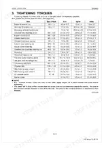
Fastener torque on the G21LD/G21HD varies by component. General use screws, bolts, and nuts carry the values listed on page 25, while specially specified torques for the engine, transmission, brakes, front axle, steering, hydraulic system, PTO, electrical system, mower, and high dump grass collector each live in their own "Tightening Torques" section, starting from page 85. As one example, the starter M terminal nut takes 9.8 to 13.7 N·m (7.2 to 10.1 ft-lbs).
What do Kubota G21LD/G21HD error codes mean?
Most G21LD/G21HD error codes point to the EPS (Electric Power Steering) system. Error Code 02 means a "4P connector disconnected"; Error Code 03 means the "4P and 16P connectors to the EPS controller disconnected". The full list of codes, their probable causes, and fixes starts on page 195, in the "Troubleshooting Based On Error Code" section.
Why does a Kubota G21 diesel mower keep cutting out?
When a Kubota G21 diesel mower dies as you engage the PTO lever, the usual culprits are an "Improper PTO wire cable adjustment" or a "Grass collector switch defective". Fixes are to "Readjust" the cable or "Replace" the switch. See page 10-S4 (page 322) for the cable adjustment and page 8-S25 (page 298) for the switch.
Is this Kubota G21LD, G21HD Workshop Manual a digital download?
A 330-page Workshop Manual in searchable PDF, available the moment your checkout completes. View it on a computer, tablet, or phone, with no shipping wait.
Can I print specific sections of this Kubota G21LD, G21HD Workshop Manual?
None at all. The PDF is DRM-free, so print whatever sections you want to carry out to the shop. Standard letter or A4 paper works fine.
Does this Kubota G21LD, G21HD manual include wiring diagrams?
Yes. You'll find full electrical schematics with wire routing diagrams, connector identification, and circuit descriptions.
Document Quality
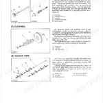
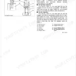
This document is a native digital PDF, allowing you to search and copy all text. The text quality is consistently crisp and clear throughout, ensuring easy readability. All diagrams and illustrations are sharp, appearing to be vector-based, with labels that are perfectly readable at any zoom level. Pages are clean, free from scan artifacts, stains, or skewed content, maintaining a professional presentation. Pages 15 and 73 serve as chapter title pages, which is standard for this type of manual.

Reviews
There are no reviews yet.