
Part of the Kubota Repair Manuals.
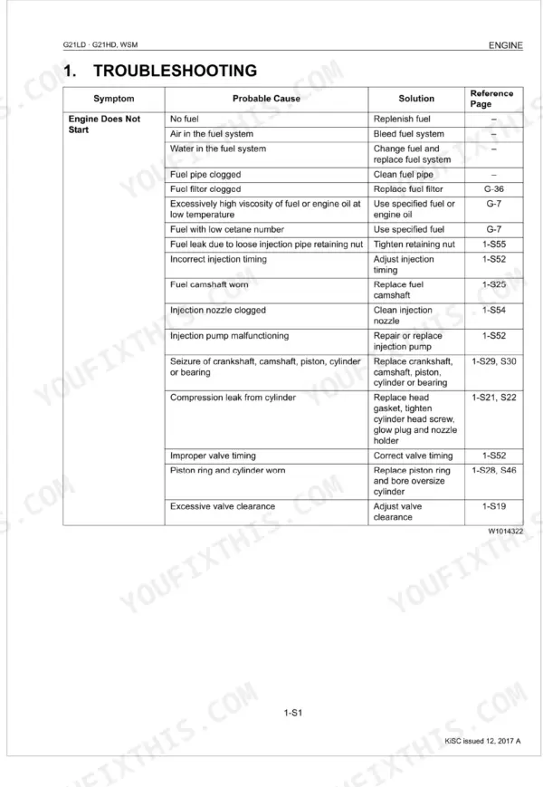
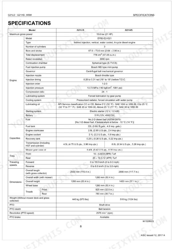
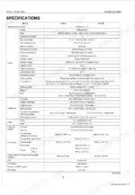
This Kubota Workshop Manual covers the G21LD and G21HD diesel front mowers. It runs to 330 pages under publication 9Y011-15092 and is written for machines powered by the D782-E2-G21 three cylinder diesel engine.
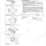
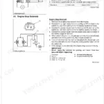
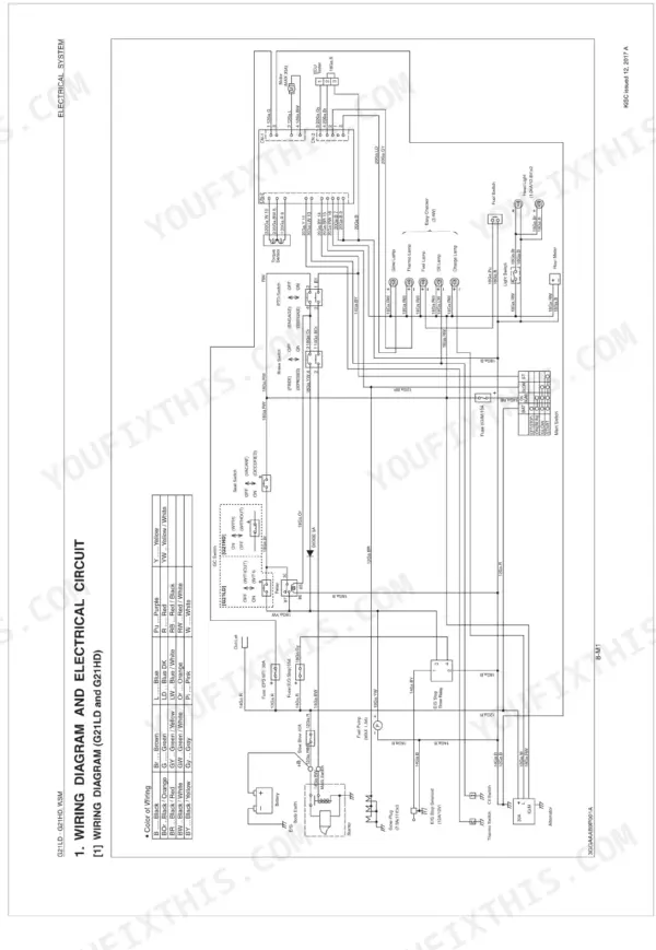
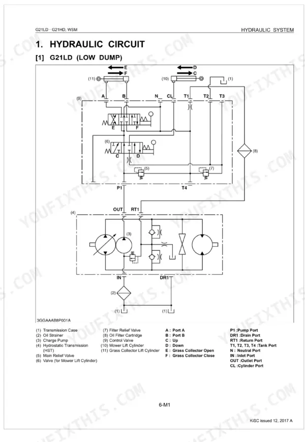
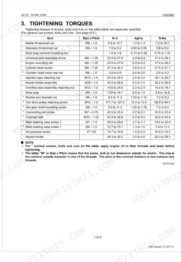
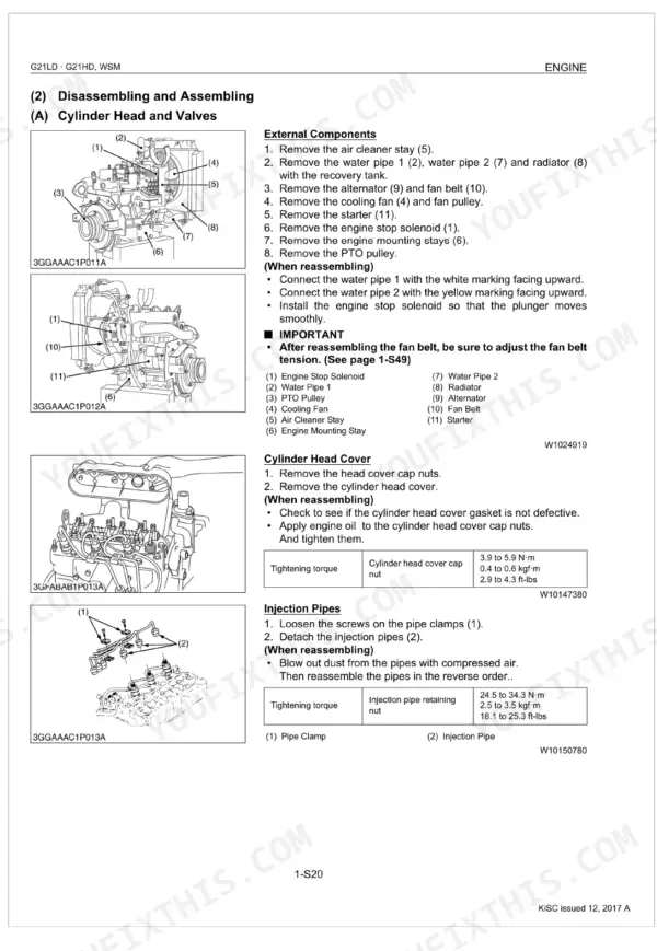
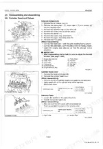
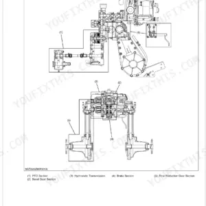
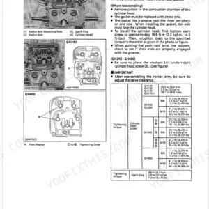
The manual works through every system: engine, the hydrostatic transmission and rear axle, brakes, front axle, steering with its power steering and EPS controller, the hydraulic system, the PTO, the electrical system with wiring diagrams, the mower deck, and the high dump grass collector. Each section carries servicing procedures, specifications, tightening torques and disassembly and assembly steps.
With this PDF an owner or independent mechanic can restore lost drive, service the mower deck, set a blade to the correct torque, diagnose the steering or hydraulics, or trace an electrical fault without a dealer visit. Download it once and keep it on a phone, tablet or shop computer, and print the pages you need at the machine.
What's Inside This Manual
| System | Pages | Key Topics |
|---|---|---|
| General | Identification, Wiring, Battery, Fuse, Connector, Handling of Circuit Tester, Lubricants, Fuel and Coolant | |
| Engine | Engine Body, Lubricating System, Cooling System, Fuel System, Checking, Disassembling and Servicing, Separating Engine | |
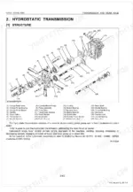
| Transmission and Rear Axle | Hydrostatic Transmission, Oil Flow, By-Pass Valve, Charge Pump, Checking, Disassembling and Servicing | |
| Brakes | Parking Brake, Pedal System, Brake Assembly, Brake Lining, Brake Drum | |
| Front Axle | Front Axle Support, Tie-Rod, Knuckle Arm, Kingpin, PTO Brake | |
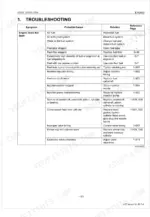
| Steering | System Configuration, Construction and Function of Main Components, Power Steering Assembly, EPS Controller, Troubleshooting Based on Each Symptom, Troubleshooting Based on Error Code, Checking, Disassembling and Servicing | |
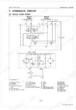
| Hydraulic System | Hydraulic Circuit, G21LD (Low Dump), G21HD (High Dump), Relief Valve (G21LD, G21HD), Mower Lifting Circuit (G21LD, Neutral, Down | |
| PTO System | PTO Clutch Spring, Front PTO Belt, PTO Brake, PTO Shaft, Tension Arm, PTO Pulley | |
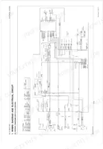
| Electrical System | Wiring Diagram and Electrical Circuit, Wiring Diagram (G21LD and G21HD), Electrical Circuit (G21LD and G21HD), Checking, Disassembling and Servicing, Battery, Starting System, Engine Key Switch Shut-Off System | |
| Mower | Mower Blade, Mower Belts, Gear Case, Center Pulley Holder, Side Blade Pulley Holder | |
| High Dump Grass Collector | Checking, Disassembling and Servicing, Disassembling Grass Collector Bag, Platform Complete, Lift Arm Assembly and Head Guard |
Every system also includes checking, disassembling and servicing, servicing specifications, tightening torques, and troubleshooting.
Quick Reference Specifications
| Specification | Value | Page |
|---|---|---|
| Belt Retainer to Front PTO Belt Clearance | 2.0 mm | p. 303 |
| Center pulley holder mounting screw | 77.4 to 90.2 N·m | p. 304 |
| Front Tip of Blade to Rear Tip of Blade Difference (Allowable Limit) | Less than 5 mm | p. 303 |
| Left Tip of Blade to Right Tip of Blade Difference (Allowable Limit) | Less than 4 mm | p. 303 |
| Charge Relief Valve Setting pressure | 0.32 to 0.41 MPa | p. 139 |
| Transmission Fluid (Including HST and Cylinder) Capacity | 4.5 L | p. 139 |
| Fuel filter replacement frequency | Every 500 Hrs | p. 27 |
| Fuel tank capacity | 22 L (5.8 U.S.gal.) | p. 31 |
| Intake air line check frequency | Every 200 Hr | p. 27 |
| Air cleaner element cleaning frequency | Every 50 Hrs | p. 27 |