


Part of the Kubota Repair Manuals.
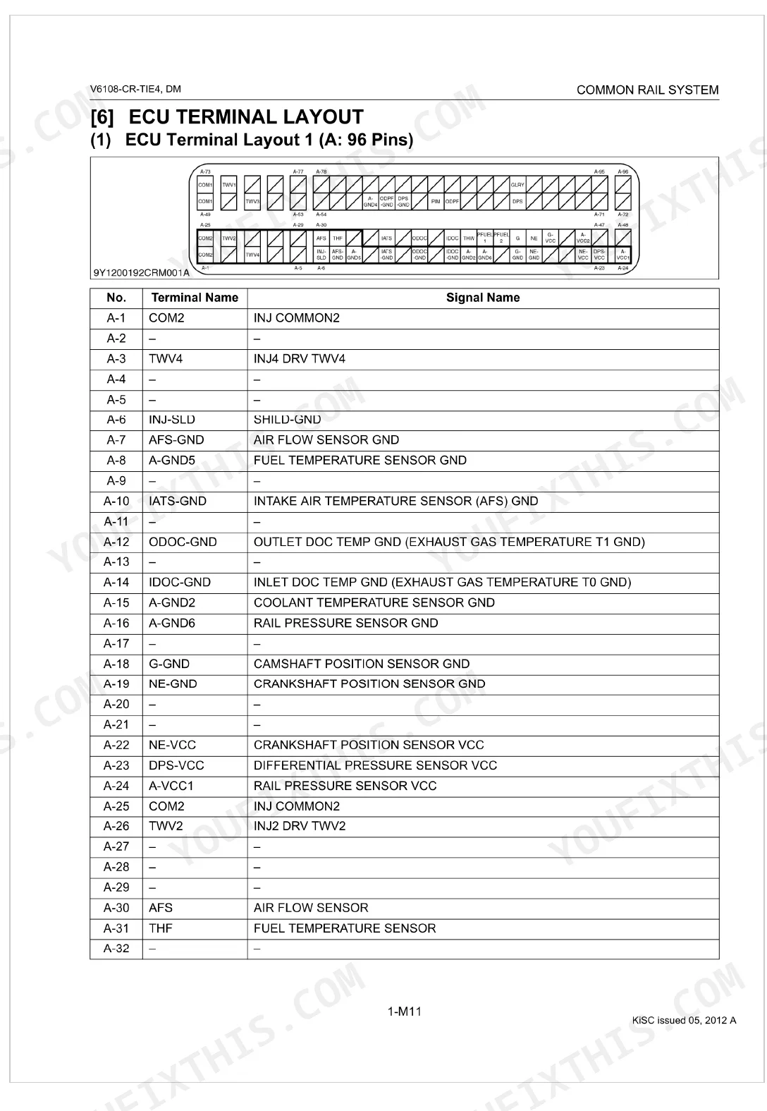
One job runs through all 317 pages of this Kubota V6108-CR-TIE4 Diagnostic Manual (OEM #9Y110-01860): pinpointing faults in the common rail system on your Kubota tractor. Coverage spans a full DTC list with SPN/FMI codes, step-by-step diagnostic procedures, ECU terminal layouts for the 96-pin A and 58-pin B connectors, and symptom-based troubleshooting for no-start, idle failure, and rail pressure faults. Active tests walk through injector cutoff, EGR actuation, glow relay checks, and supply pump difference learning. Confirm idle at 800 to 850 rpm, check no-load maximum at 2350 to 2400 rpm, and compare boost against the 100 kPa spec. When a generic scan tool leaves you burning time, pull the DTC by bookmark or keyword search and follow the factory procedure to the fix.
What's Inside This Kubota V6108-CR-TIE4 Manual
| System | Pages | Key Topics |
|---|---|---|
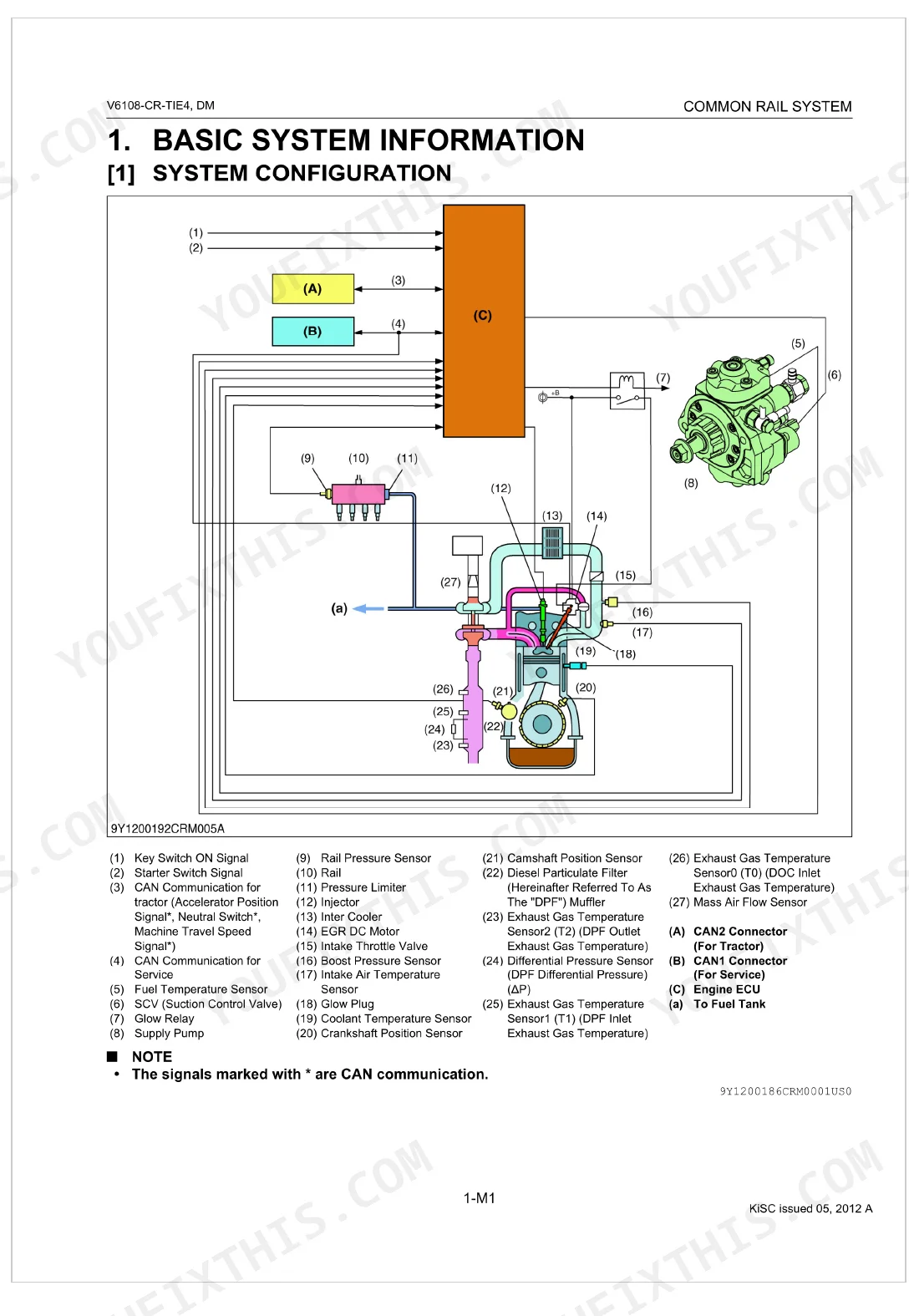
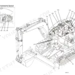
| Common Rail System Mechanism | 7-24 | Basic System Information, System Configuration, Fuel System, Intake and Exhaust System, Wiring Diagram, System Wiring Diagram, Available Data Monitor Signals (Level 2), Monitor Items |
| Active Test and Supply Pump Difference Learning | 43-44 | Injector Non-Injection Instruction, EGR Actuation Test, Glow Relay Actuation Test, Supply Pump Difference Learning, Operating Conditions → Specified Tool Conditions |
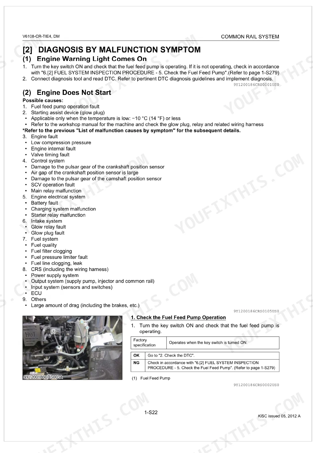
| Diagnosis by Malfunction Symptom | 45-86 | List of Malfunction Causes by Symptom, Engine Warning Light Comes on |
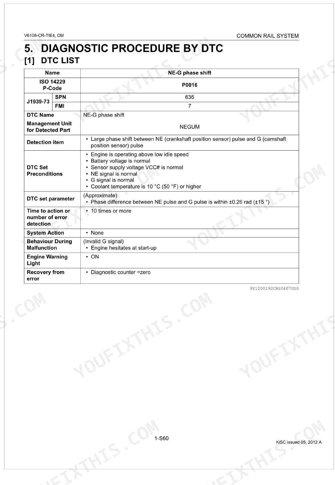
| Diagnostic Procedure by Dtc | 87-283 | Dtc List, Ne - G Phase Shift, Intake Air Temperature Built-In Maf Sensor: Abnormality, Pressure Limiter Emergency Open, High Rail Pressure, SCV Stuck, Fuel Leak |
| Inspection Procedure for Each System | 284-316 | ECU Circuit), Measure the ECU +Bp and Ground Voltage, Check the Relay Terminal Voltage -1, Check the Relay Terminal Voltage - 2, Check the Relay Terminal Voltage - 3, Check the Relay Terminal Voltage - 4, Check the Relay Terminal Voltage - 5, Check the Relay Terminal Voltage - 6 |
| Contact Information | 317 | Editor, Kubota Farm & Industrial Machinery Service, Ltd., Kubota Corporation |
Quick Reference Specifications
| Specification | Value | Page |
|---|---|---|
| Fuel filter replacement interval | every 500 operation hours | p. 306 |
| Air cleaner element cleaning interval | every 250 hours | p. 301 |
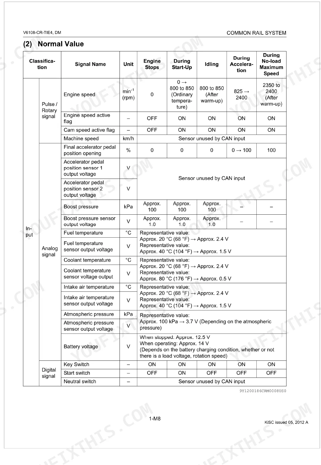
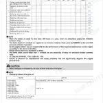
| Engine Speed (Idling) | 800 to 850 min⁻¹ (rpm) | p. 16 |
| Engine Speed (No-load Maximum Speed) | 2350 to 2400 min⁻¹ (rpm) | p. 16 |
| Boost Pressure (Approx.) | 100 kPa | p. 16 |
| Battery Voltage (Stopped) | Approx. 12.5 V | p. 16 |
| Battery Voltage (Operating) | Approx. 14 V | p. 16 |
| Target Rail Pressure (Idling) | 40 to 50 MPa | p. 17 |
| Target Rail Pressure (No-load Maximum Speed) | 95.0 to 115 MPa | p. 17 |
| Target Suction Control Valve (SCV) Current (Idling) | Approx. 1800 mA | p. 17 |
| DPF Regeneration Time Interval (High Frequency) | within 30 min. | p. 139 |
| Air Cleaner Element Cleaning/Replacement Interval | every 250 hours | p. 301 |
Kubota V6108-CR-TIE4 Common Problems This Manual Covers
Fault code P0087 pressure limiter emergency open logged, engine in derate
Check rail pressure in the live data monitor before and during fault onset. Verify no air exists in the fuel system by inspecting the high-pressure side connections. Confirm rail pressure sensor signal is within range; target idle pressure is 40 to 50 MPa per page 17. Pull the full DTC list on page 87 for any accompanying codes before replacing components.
Manual Section: Diagnostic Procedure by DTC p. 87Engine cranks normally but will not start, no active fault codes on data monitor
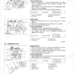
Verify fuel feed pump operation first: listen for the prime cycle at key-on. Follow the no-start diagnostic workflow on page 49, checking both crankshaft and camshaft position sensor signals at the ECU pinout. Confirm ECU supply voltage reads approximately 12.5 V with key off before suspecting injector circuit faults.
Manual Section: Diagnosis by Malfunction Symptom p. 49SCV stuck code P0089 active, rail pressure unstable and hunting at idle
Read rail pressure in data monitor mode; target at idle is 40 to 50 MPa per page 17. If pressure fluctuates beyond this range, inspect suction control valve wiring for open or short circuits. Verify SCV current at idle reads approximately 1800 mA. Confirm no air exists in the fuel system before condemning the SCV.
Manual Section: Diagnostic Procedure by DTC p. 87Battery voltage fault code P0562 or P0563 stored, ECU intermittently losing power
Measure ECU terminal voltage: should read approximately 14 V with engine running and 12.5 V with engine stopped, per page 16. Inspect the wiring harness at battery and ECU terminal connections for corrosion or spread pins. Test main relay continuity. Confirm alternator output is stable before condemning the ECU.
Manual Section: Diagnostic Procedure by DTC p. 87Injector circuit fault code active, rough idle with occasional misfires at low load
Test injector coil resistance at each injector connector: specification is 0.35 to 0.55 Ω per page 189. Resistance outside this range points to a failed injector or open harness. Run the injector non-injection instruction active test on page 43 to isolate the misfiring cylinder. Inspect connector pins for moisture or corrosion.
Manual Section: Diagnostic Procedure by DTC p. 189Poor acceleration and low power under load, DTC check clean, smoke visible at exhaust
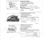
Inspect the air intake system: check air cleaner condition on page 301 (element cleaning interval is 250 hours). Verify boost pressure reaches approximately 100 kPa under full load. Review crankshaft and camshaft position sensor data and rail pressure in data monitor mode; target rail pressure at no-load maximum speed is 95 to 115 MPa per page 17.
Manual Section: Diagnosis by Malfunction Symptom p. 45Frequently Asked Questions
What are the recommended service intervals?
Clean the air cleaner element (Primary and Secondary) every 250 hours. Replace it once a year or after every sixth cleaning, whichever comes first. The fuel filter gets replaced every 500 operation hours. p. 301
What fluids and capacities does this machine require?
Diesel fuel needs a minimum Cetane Rating of 45, preferably above 50, with sulfur content no greater than 0.0015% (15 ppm) and water content below 0.05% (500 ppm). For engine oil, use API Service Classification CF grade or higher. p. 302
How to troubleshoot engine won't start?
Start by turning the key switch ON to confirm the fuel feed pump runs. If it does not, see page 1-S279 for the "Check the Fuel Feed Pump" procedure. Likely causes include a fuel feed pump fault, starting assist device problems (especially below 10 °C (14 °F)), engine faults, or control system malfunctions. p. 49
How to reset error codes or warning lights?
After completing repairs, erase the Diagnostic Trouble Codes (DTCs). Many recovery procedures, such as the one for P0016, specify "Diagnostic counter = zero" on recovery. Use the diagnosis tool to clear DTCs and check whether they return. p. 28
What are the common electrical problems?
Most electrical faults are open or short circuits in wiring harnesses and sensor circuits, flagged by DTCs like P0201 to P0204 for injector harness/coil open circuits. Others cover battery voltage abnormalities (P0562/P0563) and sensor supply voltage abnormalities (P0642/P0643, P0652/P0653). To inspect the system, check ECU terminal voltage and resistance as detailed on page 1-S281. p. 281
What format is this Kubota V6108-CR-TIE4 manual in?
It is a 317-page searchable PDF ready to download right away. The file opens on any device, so you can pull it up on your phone while you're under the hood. No shipping, no waiting.
Is this Kubota V6108-CR-TIE4 Diagnostic Manual printable?
None at all. The PDF is DRM-free, so print whatever sections you want to carry out to the shop. Standard letter or A4 paper works fine.


Reviews
There are no reviews yet.