


Match the part on your bench to a Kubota number before you call the counter. The LA703 catalog runs to 29 pages of exploded-view diagrams, one per assembly: main frame, side frame, boom, bucket, the control valve down to its detent plug kit and load check valve, control lever, hydraulic hoses and tubes, and the internals of both boom and bucket cylinders. Every callout ties back to a numbered parts list, so what you pulled off the machine lines up with a Kubota number in seconds. The factory reference puts the control valve assembly at 7.08 kgf; the boom and bucket seal kits each weigh 0.03 kgf. No more squinting at blurry microfiche. Jump straight to any section through the bookmarks and have the right reference on screen before the parts desk answers.
What's Inside This Kubota LA703 Parts Manual
| System | Pages | Key Topics |
|---|---|---|
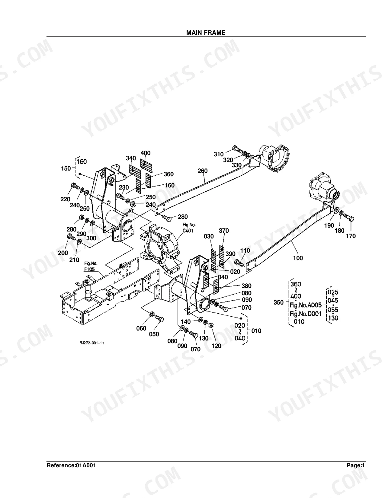
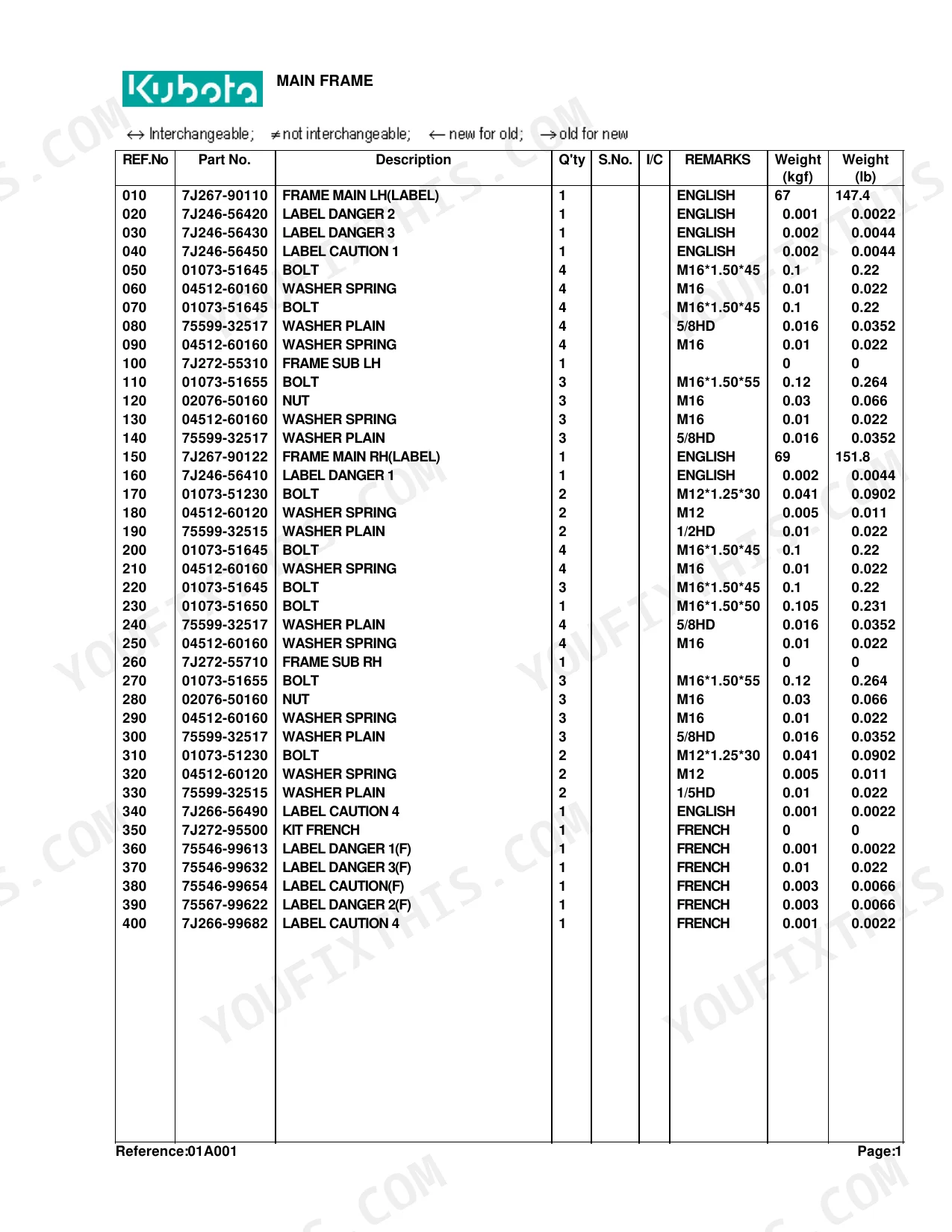
| Main Frame | 4-5 | Frame Main Lh(Label), Frame Sub Lh, Frame Main Rh(Label), Bolt, Washer Spring, Nut |
| Side Frame | 6-7 | Frame Side Lh(Label), Pin Mount, Kit Guard Front, Bolt, Washer Spring, Label Control |
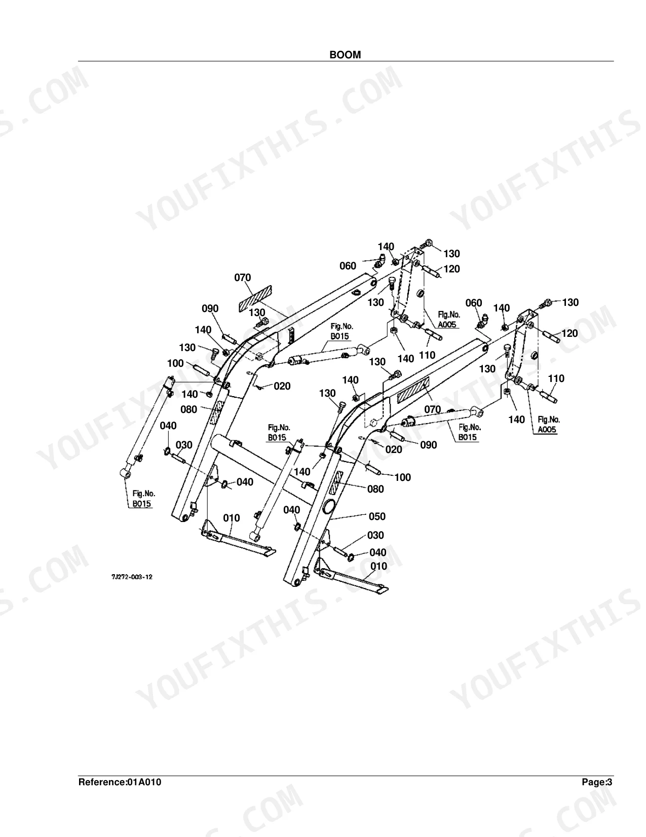
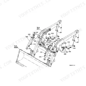
| Boom | 8-9 | Stand, Pin Spring Lock, Fitting Grease, Label Kubota, Nut Lock |
| Bucket | 10-11 | Edge 1 Cutting, Pin 3, Hex.Bolt, Nut Lock, Edge 2 Cutting |
| Control Valve | 12-13 | Stay Valve, Assy Valve Control, Assy Adapter, O-Ring, Nipple, Cap Dust |
| Control Valve [Component Parts] | 14-15 | Assy Valve Control, Kit Plug Detent 1, O Ring, Ring Back Up, Ball, Kit Valve Load Check |
| Control Lever | 16-17 | Lever, Bush, Joint Rod End, Grip Lever, Lever Control, Boot Control Lever |
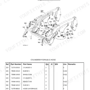
| Cylinder/Hydraulic Hose | 18-19 | Cylinder 1, Elbow 1, Adapter(Nptf), Cylinder 2, Band Code, Hose 8 Hydraulic |
| Hydraulic Hose(Hyd.Outlet Block) | 20-21 | Hose 5 Hydraulic, Hose 6 Hydraulic, Hose 10 Hydraulic, Band Code, Adapter 1, Block Hydraulic |
| Hydraulic Tube | 22-23 | Tube 1 Hydraulic, Tube 2 Hydraulic, Cover Clamp, Hose 2 Hydraulic, Coupler, Plug Dust |
| Cylinder (Boom) [Component Parts] | 24-25 | Nut, Tube 1 Comp, Rod 1 Comp, Head, Piston 1 |
| Cylinder (Bucket) [Component Parts] | 26-27 | Nut, Head, Kit 1 Seal, Tube 1 Comp, Piston 1 |
| Accessories and Service Parts | 28-29 | Operator's Manual |
Quick Reference Specifications
| Specification | Value | Page |
|---|---|---|
| ASSY VALVE CONTROL weight | 7.08 kgf | p. 13 |
| KIT VALVE LOAD CHECK weight | 0.04 kgf | p. 15 |
| KIT 1 SEAL(2328/11) weight | 0.03 kgf | p. 25 |
| KIT 1 SEAL(2326/11) weight | 0.03 kgf | p. 27 |
| BUSH weight | 0.01 kgf | p. 17 |
| PIN MOUNT weight | 1.35 kgf | p. 7 |
| PIN SPRING LOCK weight | 0.015 kgf | p. 9 |
| FRAME MAIN LH(LABEL) Weight | 67 kgf | p. 5 |
| BOLT Size | M16*1.50*45 | p. 5 |
| WASHER SPRING Size | M16 | p. 5 |
| FRAME SIDE LH(LABEL) Weight | 18 kgf | p. 7 |
| FITTING GREASE Type | 90DEG. | p. 9 |
Kubota LA703 Common Problems This Manual Covers
Need the correct seal kit part number for a leaking Kubota LA703 main boom cylinder. p. 25
Start with the exploded cylinder view on page 24 to pin down the seal kit components. Match KIT 1 SEAL(2328/11) on page 25 to your cylinder bore, and note its 0.03 kgf weight. Then cross-check the piston and head part numbers before ordering.
Manual Section: Cylinder (Boom) [Component Parts]Internal leakage past the main control valve with the loader unable to lift or curl. p. 13
Trace the hydraulic parts diagram on page 12 to the ASSY VALVE CONTROL. Confirm you need the full 7.08 kgf assembly listed on page 13. Pull the matching O-rings, nipples, and 3/8NPT adapter fittings from the parts list so nothing is missed on the order.
Manual Section: Control ValveWorn pivot pins and bushings with excessive play and clunking in the loader arms. p. 9
Compare the boom attachment diagram on page 8 to find the correct pin placements. Locate the pin spring locks on page 9, listed at 0.015 kgf. Order the 90DEG. grease fittings with them to finish the linkage rebuild.
Manual Section: BoomInternal fluid bypass at the curl cylinder seals with the bucket drifting down under load. p. 27
Open the exploded view on page 26 to break down the curl cylinder. Pick out KIT 1 SEAL(2326/11) on page 27, listed at 0.03 kgf. Then tie the piston and head part numbers to your exact serial number break before ordering.
Manual Section: Cylinder (Bucket) [Component Parts]Frequently Asked Questions
Where can I find the Kubota LA703 parts list or owner’s manual?
This catalog lists parts for the main components of the LA703 loader, including the Main Frame, Side Frame, Boom, and Control Valve. The Operator's Manual shows up as an accessory too, under part number 7J272-69110 (English) or 7J272-95910 (French).
What are the replacement specifications for control valve?
The control valve breaks down into numbered parts: YW240-00102 for the ASSY VALVE CONTROL, 7J243-61850 for the ASSY ADAPTER, and 75560-61950 for ASSY ELBOW 2 ADJUSTA. Bolts, nuts, and O-rings carry their own numbers and sizes too, for instance bolt 01173-51230 at M12*1.25*30.
What are the replacement specifications for hydraulic hoses?
Each hydraulic hose carries its own number: 7J267-66610 for HOSE 8 HYDRAULIC, 7J267-66620 for HOSE 9 HYDRAULIC, and 7J272-66630 for HOSE 10 HYDRAULIC. The hydraulic outlet block adds its own, such as 7J266-66710 (HOSE 5 HYDRAULIC) and 7J261-66410 (HOSE 6 HYDRAULIC).
What do I get after purchasing this Kubota LA703 manual?
The full 29-page searchable Parts Catalog downloads as a PDF the moment payment clears. Open it on a laptop, tablet, or phone right at the workbench.
Is this Kubota LA703 Parts Catalog printable?
Yes. The PDF carries no DRM, so you can print any page or section your shop needs. It works with any standard printer.
Document Quality
This document is a scanned copy of a parts book, featuring an OCR layer that allows you to search and copy text from the part number lists. Text quality on these searchable pages is crisp and easy to read. The diagrams and illustrations are clear raster images, and all labels within them are readable. The pages are clean with no noticeable scan artifacts or marks, and there are no blank or filler pages.


Reviews
There are no reviews yet.