


Need the correct part number for your TL420A loader? This 30-page Kubota TL420A Parts Catalog spans every assembly: side frame, boom, control valve, levers, link, cover, hydraulic cylinders, tubes, and hose routing. Fourteen pages of indexed parts lists break down the control valve internals (inlet section, spool, detent kit), with separate cylinder sections for boom and bucket that each show tube, rod, piston, head, and seal kit at the individual part number. Check the weight spec before you order: the left-hand side frame is 16 kgf, the right is 16.5 kgf, and boom pins are called out individually at 0.365 and 0.425 kgf. Quit paying dealer markup on parts you can't identify. Bookmarked by assembly, it opens on a tablet so you jump straight to a section without scrolling.
What's Inside This Kubota TL420A Parts Manual
| System | Pages | Key Topics |
|---|---|---|
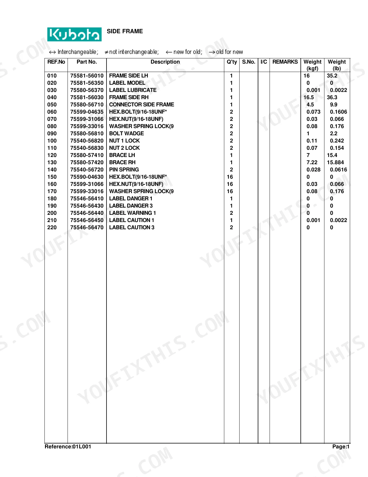
| Side Frame | 3-4 | Frame Side Lh, Frame Side Rh, Connector Side Frame, Brace Lh, Brace Rh, Hex.Bolt |
| Boom | 5-6 | Pin, Fitting Grease, Comp Link, Bucket, Edge Cutting |
| Control Valve | 7-8 | Stay Valve, Hex.Bolt, Washer Spring Lock, Valve Control, Assy Adapter, O-Ring |
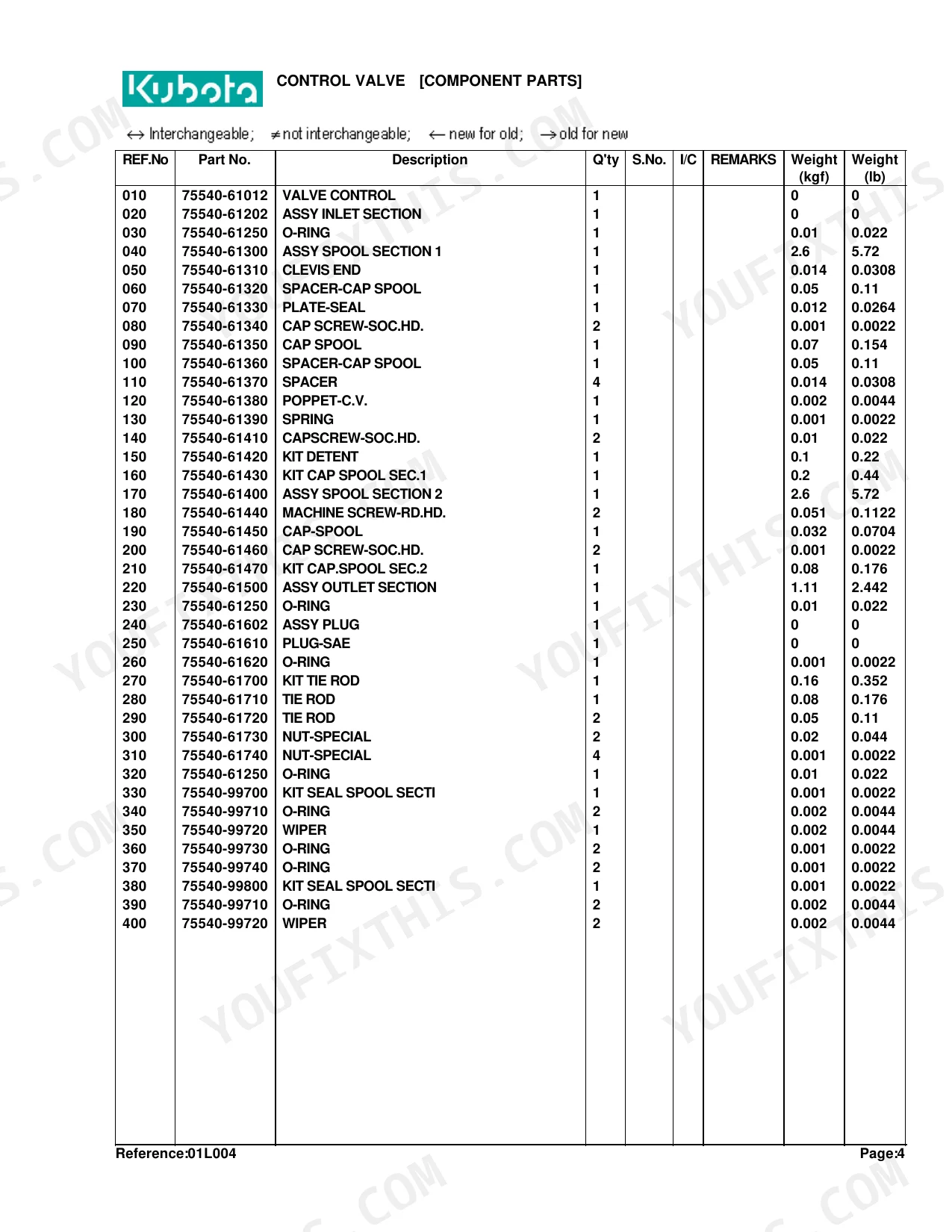
| Control Valve [Component Parts] | 9-10 | Valve Control, Assy Inlet Section, Assy Spool Section, Cap Spool, Kit Detent, Kit Tie Rod |
| Lever | 11-12 | Bushing, Collar, Cir-Clip External, Rod, Pin Cottre |
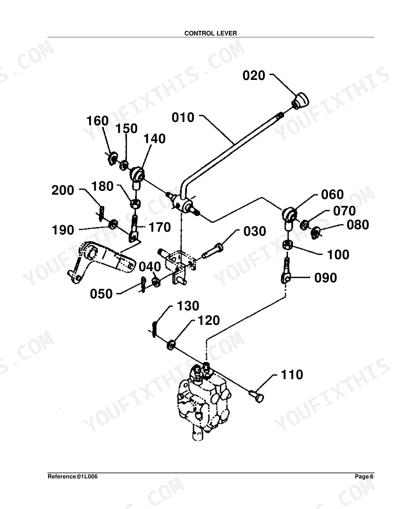
| Control Lever | 13-14 | Lever Control, Grip Lever, Pin Clevis, Joint Rod End, Hex.Jam Nut, Rod |
| Control Cover | 15-16 | Cover, Hex.Bolt, Washer Sprint Lock, Label Control, Assy Limiter, Cushion |
| Link | 17-18 | Bushing, Collar, Cir-Clip External, Rod, Hex.Jam Nut |
| Cylinder and Hydraulic Hose | 19-20 | Cylinder 1, Cylinder 2, Band Code, Hose 1 Hydraulic, Hose 2 Hydraulic, Hose 8 Hydraulic |
| Cylinder (Boom) [Component Parts] | 21-22 | Tube 1 Comp, Rod 1 Comp, Head 1, Piston 1, Kit 1 Seal |
| Cylinder (Bucket) [Component Parts] | 23-24 | Tube 2 Comp, Rod 2 Comp, Head, Piston, Kit Seal |
| Hydraulic Tube | 25-26 | Tube 1 Hydraulic, Tube 2 Hydraulic, Tube 3 Hydraulic, Tube 4 Hydraulic, Clamp 1, Clamp 2 |
| Delivery and Return Hose | 27-29 | Hose 5 Hydraulic, Hose 6 Hydraulic, Hose 7 Hydraulic, Band Code, Adapter, Joint |
| Accessories and Service Parts | 30 | - |
Quick Reference Specifications
| Specification | Value | Page |
|---|---|---|
| FRAME SIDE LH Weight | 16 kgf | p. 4 |
| FRAME SIDE RH Weight | 16.5 kgf | p. 4 |
| CONNECTOR SIDE FRAME Weight | 4.5 kgf | p. 4 |
| BOOM PIN 1 Weight | 0.365 kgf | p. 6 |
| BOOM PIN 2 Weight | 0.425 kgf | p. 6 |
| HOSE 1 HYDRAULIC Length | 27.8 inches | p. 20 |
| HOSE 2 HYDRAULIC Length | 29.3 inches | p. 20 |
| HOSE 8 HYDRAULIC Length | 22.0 inches | p. 20 |
| HOSE 9 HYDRAULIC Length | 41.5 inches | p. 20 |
| HOSE 5 HYDRAULIC Length | 53.6 inches | p. 28 |
Kubota TL420A Common Problems This Manual Covers
Kubota TL420A boom cylinder rod seal leaking, can't confirm correct seal kit for the assembly p. 21
Open to page 21 for the Cylinder (Boom) Component Parts exploded view. Kit 1 Seal appears as a discrete line item alongside Tube 1 Comp, Rod 1 Comp, Head 1, and Piston 1. If you are replacing the delivery hose at the same time, cross-check page 27, where Hose 5 Hydraulic measures 53.6 inches.
Manual Section: Cylinder (Boom) [Component Parts]Loader arms drift down after shutdown, can't identify the failed control valve component to order p. 9
Go to page 9 for the Control Valve Component Parts exploded view. Assy Inlet Section, Assy Spool Section, Kit Detent, and Kit Tie Rod each list as separate orderable assemblies. Cross-reference the Control Valve assembly view on page 7 first. Hose 8 Hydraulic measures 22.0 inches (page 19); inspect the adjacent hose if the valve fitting shows wear.
Manual Section: Control Valve [Component Parts]Hydraulic hose damaged or leaking, can't match the correct replacement length from the catalog p. 19
Check page 19 for the Cylinder and Hydraulic Hose exploded view, which shows Hose 1 (27.8 inches), Hose 2 (29.3 inches), and Hose 8 (22.0 inches) with their routing positions. For main delivery and return lines, turn to page 27, where Hose 5 Hydraulic runs 53.6 inches. Measure the damaged hose first to confirm the replacement length.
Manual Section: Cylinder and Hydraulic HoseExcessive play at boom or frame pivot points, can't identify correct replacement pins and bushings p. 5
Turn to page 5 for the Boom exploded view, which lists pins, grease fittings, and comp link components. Boom Pin 1 weighs 0.365 kgf and Boom Pin 2 weighs 0.425 kgf (page 6); use those specs to verify the right pin before assembly. For side frame pivot hardware, see pages 3-4.
Manual Section: BoomBucket cylinder leaking, need to identify seal kit and internal component part numbers p. 23
Flip to page 23 for the Cylinder (Bucket) Component Parts exploded view. The parts list separates Tube 2 Comp, Rod 2 Comp, Head, Piston, and Kit Seal as individual line items. While ordering, also verify Hose 2 Hydraulic at 29.3 inches (page 20) if the adjacent hose shows swelling or fitting damage alongside the cylinder leak.
Manual Section: Cylinder (Bucket) [Component Parts]Side frame cracked or damaged, need to identify correct replacement parts and connector hardware p. 3
Pull up pages 3-4 for the Side Frame exploded view and parts list. Frame Side LH weighs 16 kgf and Frame Side RH weighs 16.5 kgf; the Connector Side Frame is a separate part at 4.5 kgf. Cross-reference these individually, since left, right, and connector pieces carry separate part numbers and are not sold as one assembly.
Manual Section: Side FrameFrequently Asked Questions
What are the replacement specifications for boom cylinder seals?
Boom cylinder seals are sold as "KIT 1 SEAL," part number 75545-63400. Each cylinder takes 2 kits, and each kit weighs 0.1 kgf (0.22 lb). See the CYLINDER (BOOM) [COMPONENT PARTS] section on page 22.
What are the replacement specifications for loader control valve components?
The control valve uses several O-rings and seal kits. "KIT SEAL SPOOL SECTI" (Part No. 75540-99700) replaces at 0.001 kgf (0.0022 lb), and the listing also covers "O-RING" (Part No. 75540-61250) and "WIPER" (Part No. 75540-99720), each with its own part number and quantity. Full detail sits in the CONTROL VALVE [COMPONENT PARTS] section on page 10.
What do I get after purchasing this Kubota TL420A manual?
A 30-page searchable PDF, ready to download the moment you buy. It works on any device, so you can pull it up on your phone right at the machine. No shipping, no waiting.
Is this Kubota TL420A Parts Catalog printable?
Yes. The PDF carries no DRM, so print any page or section your shop needs. It runs on any standard printer.
Document Quality
This document is a scanned PDF with an OCR layer, allowing you to search and copy text from the parts lists and instruction pages. The text is crisp and easy to read, though some minor OCR errors are present in the searchable layer. Diagrams are clear raster images, and all labels are easily readable. Pages are clean with no notable scan artifacts, and there is one 'IMAGE NOT AVAILABLE' placeholder page for a missing diagram.


Reviews
There are no reviews yet.