


All 298 pages of this Case Ih Agriculture Flex Air 810 Service Manual (OEM #84588406) focus on one machine: the Air 810 Applicator, from drop box transmission through granular chemical delivery. Inside: hydraulic schematics for both fixed and variable displacement pump circuits, wiring diagrams covering harnesses and application fertilizer control, and torque tables for standard and hydraulic hardware. You also get pneumatic system procedures covering the foam marker, boom locks, auger cleanout doors, and rear spray bar, plus a full granular chemical hydraulic fan system breakdown. Fill the hydraulic tank to 113.6 l (30 US gal), set the boom and auger gate relief valve to 124 bar (1800 psi), and torque the fixed displacement pump mounting bolts to 34 N·m (25.1 lb ft). Your machine is down. Search by keyword, jump to any bookmarked section, and pull up the factory spec before you reach for a wrench.
What's Inside This Case IH Flex Air 810, Flex Air 810 Applicator Manual
| System | Pages | Key Topics |
|---|---|---|
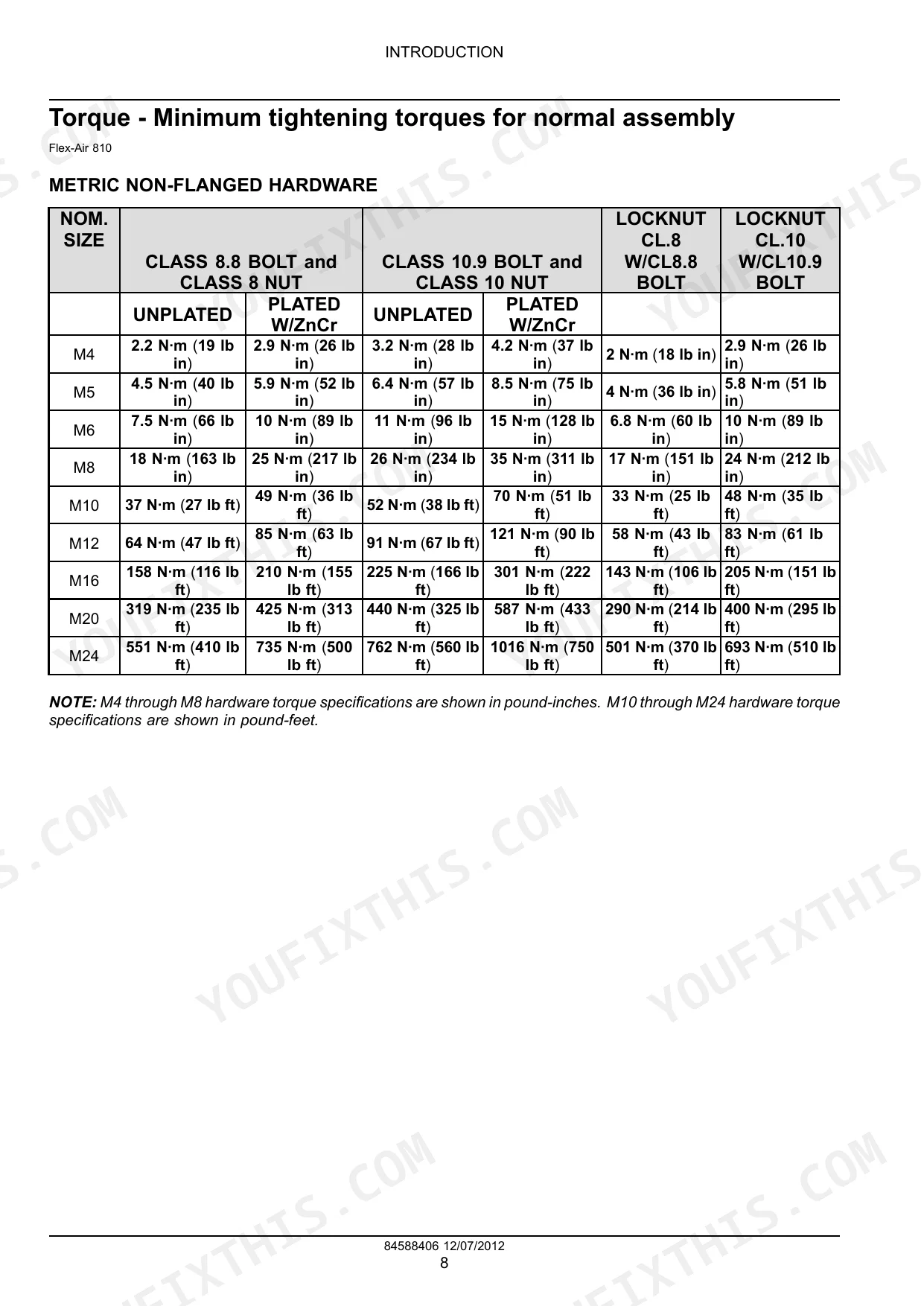
| Introduction | 4-21 | Personal Safety - Do Not Operate Tag, Personal Safety - Signal Words, Personal Safety - California Proposition 65 Warning, Basic Instructions - Shop and Assembly |
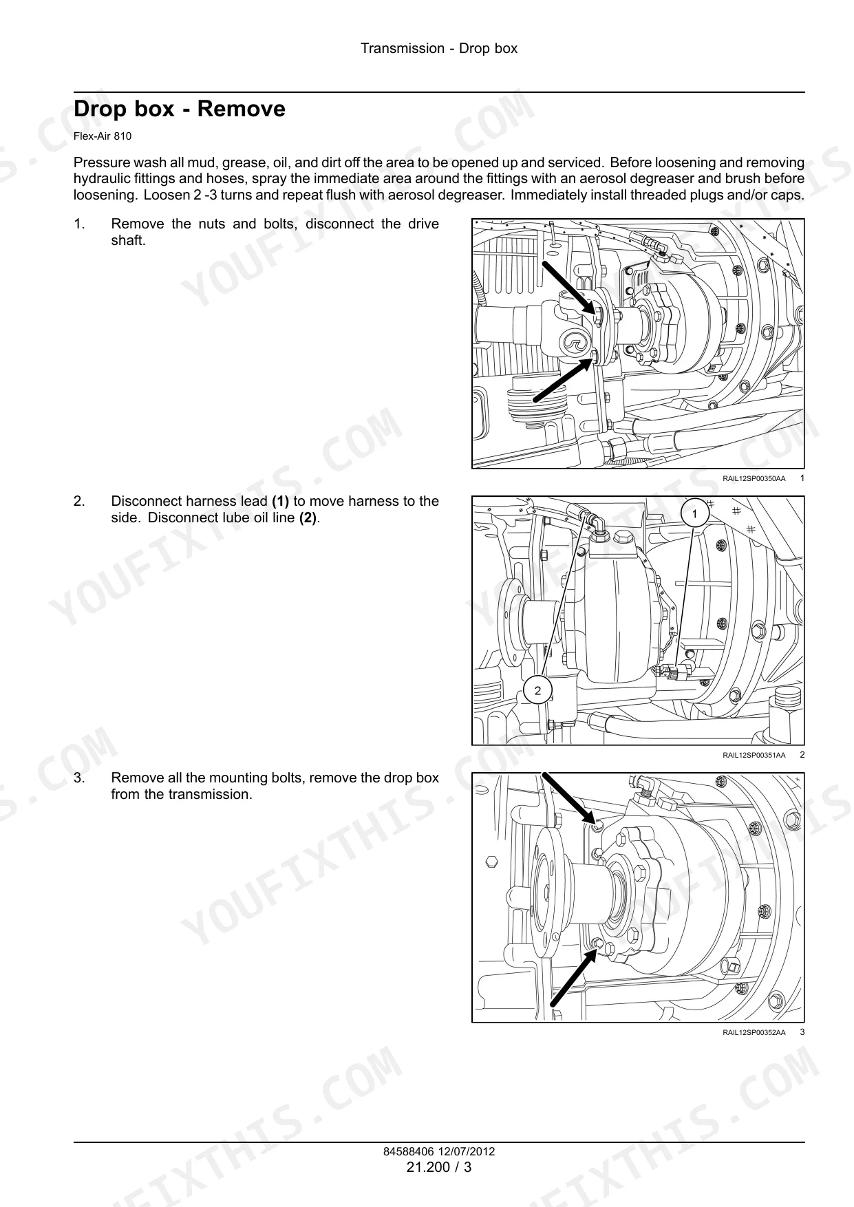
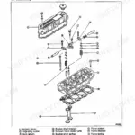
| Transmission - 21 | 22-41 | Drop Box |
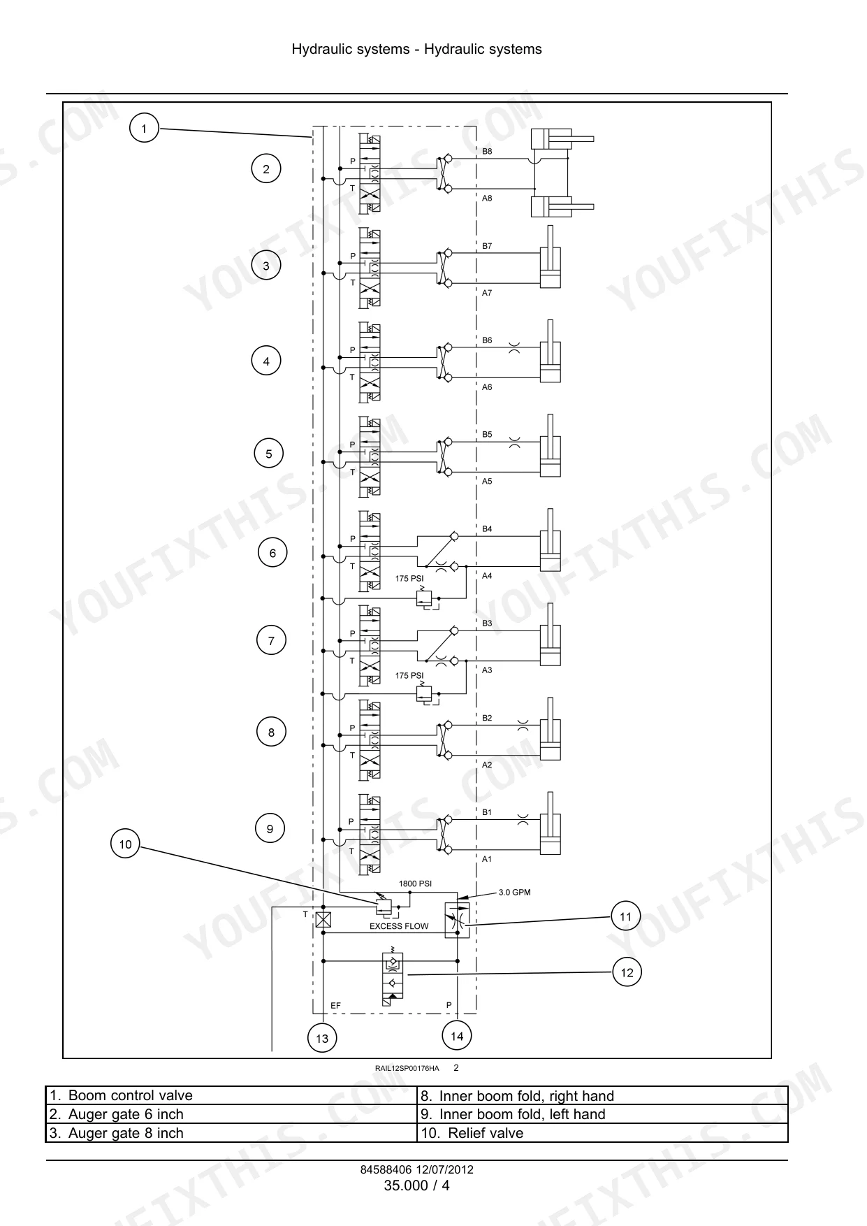
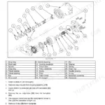
| Hydraulic Systems - 35 | 42-103 | Boom and Auger System Control Overview, Fixed Displacement Pump, Variable Displacement Pump, Granular Chemical Hydraulic Fan System, Hydraulic Part Replacement |
| Pneumatic System - 36 | 104-115 | Foam System Overview, Boom Locks Overview, Auger Cleanout Doors Overview, Rear Spray Bar Overview |
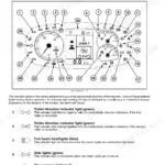
| Electrical Systems - 55 | 116-235 | Harnesses and Connectors, Application Fertilizer Control |
| Chemical Applicators - 63 | 236-283 | Granular Chemical System |
| Spraying - 78 | 284-292 | Spraying Pump |
| Electrical Schematic | 293-298 | Compartment Interface, Foam Marker, Boom Controls, Gate Controls, Transmission Controls, CAN Speed Node |
Quick Reference Specifications
| Specification | Value | Page |
|---|---|---|
| Blower magnetic speed sensor adjustment clearance | 3 - 6 mm (0.125 - 0.25 in) | p. 77 |
| Hydraulic Tank Capacity | 113.6 l (30 US gal) | p. 55 |
| Fixed Displacement Pump Mounting Bolt Torque | 34 N·m (25.1 lb ft) | p. 56 |
| Boom and Auger Gate Circuit Relief Valve Setting | 124 bar (1800 psi) | p. 45 |
| Auger Hydraulic Circuit Relief Valve Setting | 186.0 bar (2700 psi) | p. 49 |
| Auger Motor Flow Control Valve Setting | 49.0 l/min (13.0 US gpm) | p. 48 |
| Blower Magnetic Speed Sensor Adjustment Gap | 3 - 6 mm (0.125 - 0.25 in) | p. 77 |
| Granular Chemical Hydraulic Fan System Charge Pressure | 25 - 26 bar (360 - 380 psi) | p. 79 |
| Maximum Allowable Continuous Case Pressure | 3.0 bar (44 psi) | p. 83 |
| Blower Motor Circuit Loop Flushing Flow Rate | 11.4 l/min (3 US gpm) | p. 85 |
| Pressure Compensated Pump Displacement | 57 cm³ (3.47 in³) | p. 240 |
| Metering Circuit Relief Valve Setting | 150.0 bar (2175 psi) | p. 241 |
Case IH Flex Air 810, Flex Air 810 Applicator Common Problems This Manual Covers
Auger motor turns slowly or stalls completely under a full hopper load
Verify the auger hydraulic circuit relief valve setting is 186.0 bar (2700 psi) per page 49. Check flow control valve output; it should supply 49.0 l/min (13.0 US gpm) to auger motors per page 48. If pressure is within spec but the motor still stalls, remove and inspect the auger motor per the Chemical Applicators section, page 236.
Manual Section: Hydraulic Systems - 35 p. 49Frequently Asked Questions
How do you fix case IH Flex Air 810 booms drift off level after one hour of operation, require manual reset?
Check the boom and auger gate circuit relief valve; it must hold 124 bar (1800 psi) per page 45. Inspect hydraulic cylinders for internal leakage by extending them fully under load and watching for drift. Pull the hydraulic schematic to trace the cylinder circuit, isolate the leaking component, and schedule replacement. p. 45
How do you fix right shutoff valve cuts out randomly during half-swath passes, valve stays open?
Inspect the shutoff valve actuator connector and wiring harness for corroded pins or chafed insulation; a broken circuit triggers error E02. Trace the circuit through the wiring diagram. Test solenoid coil continuity, then verify boom gate circuit pressure holds 124 bar (1800 psi) per page 45 before condemning the control module. p. 131
How do you fix hydraulic fan motor overheats and trips thermal shutdown after two to three hours of operation?
Verify granular chemical hydraulic fan system charge pressure reads 25-26 bar (360-380 psi) per page 79; low charge causes heat buildup. Measure blower motor circuit loop flushing flow; it must reach 11.4 l/min (3 US gpm) per page 85. Set the blower magnetic speed sensor gap to 3-6 mm (0.125-0.25 in) per page 77 and clean all fan inlet screens. p. 79
How do you fix hopper sensor reads erratically, application rate jumps and drops unpredictably during a run?
Inspect the hopper sensor connector and harness for corrosion or loose terminals. Measure the metering circuit relief valve; it must hold 150.0 bar (2175 psi) per page 241. Confirm the Flex-Air return manifold relief valve reads 24.0 bar (350 psi) on page 243. Clean the sensor mounting surface and reseat the connector before swapping the module. p. 241
Is this Case Ih Agriculture Flex Air 810, Air 810 Applicator manual a digital?
You get a 298-page searchable PDF that downloads instantly after checkout. Open it on your laptop, tablet, or phone, and bring it right to the shop floor.
Reviews
There are no reviews yet.