


Need the exact rebuild procedures for your Case IH Maxxfarm 40 tractor? This 230-page service manual (OEM #47673550) covers R41 and R47 configurations from cylinder head to final drive. You get hydraulic schematics with full fluid routing, wiring diagrams for the starter, alternator, and glow plug circuits, plus a troubleshooting section that maps every fuel, lubrication, cooling, electrical, and mechanical complaint to a specific root cause. The transmission section walks through clutch housing, HST unit, 4WD quick-turn, independent PTO, and final drive in complete factory sequence. Thermostat opens at 76.5±1.5°C (170±2.7°F); schedule your fuel filter swap every 500 service hours. No more forum rabbit holes for a spec your machine needs today. Bookmarked and keyword-searchable: open it on any device and start wrenching.
What's Inside This Case IH MaxxFarm 40-50 Manual
| System | Pages | Key Topics |
|---|---|---|
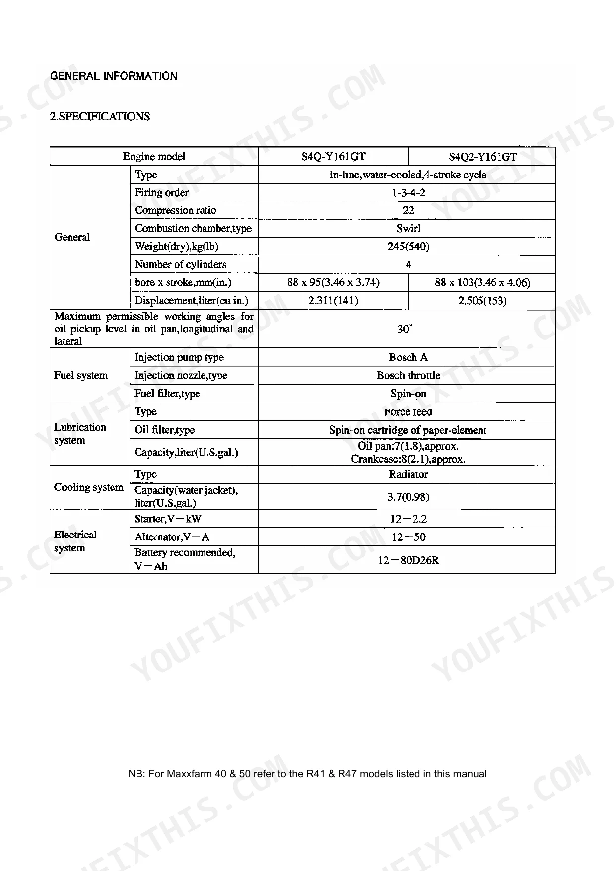
| General Information | 3-10 | General, Typical Engine Arrangements, Engine Serial Number Location, Engine Model Designation, Specifications |
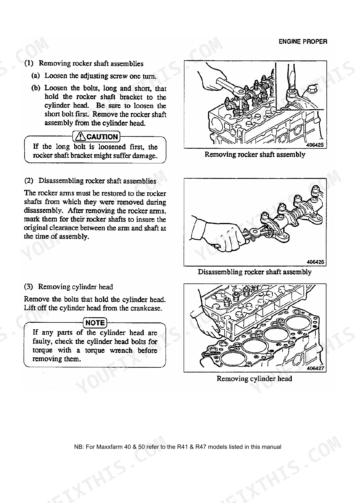
| Engine | 11-72 | Cylinder Head and Valve Mechanism (Disassembly, Removing Rocker Shaft Assemblies, Disassembling Rocker Shaft Assemblies, Removing Cylinder Head, Removing Valves and Valve Springs, Removing Valve Stem Seals, Cleaning Cylinder Head, Measuring Piston Projection) |
| Cooling System | 73-74 | General, Water Pump (Inspection), Thermostat (Testing) |
| Fuel System | 75-83 | General, Priming the Fuel System (Filter, Injection Pump), Disassembly (Disconnecting Fuel Pipes, Removing Fuel Injection Nozzles, Removing Fuel Injection Pump) |
| Lubrication System | 84-87 | General, Oil Pump (Disassembly, Inspection, Assembly), Oil Filter (Inspection), Pressure Relief Valve (Inspection) |
| Electrical System | 88-100 | Starter (Disassembly) |
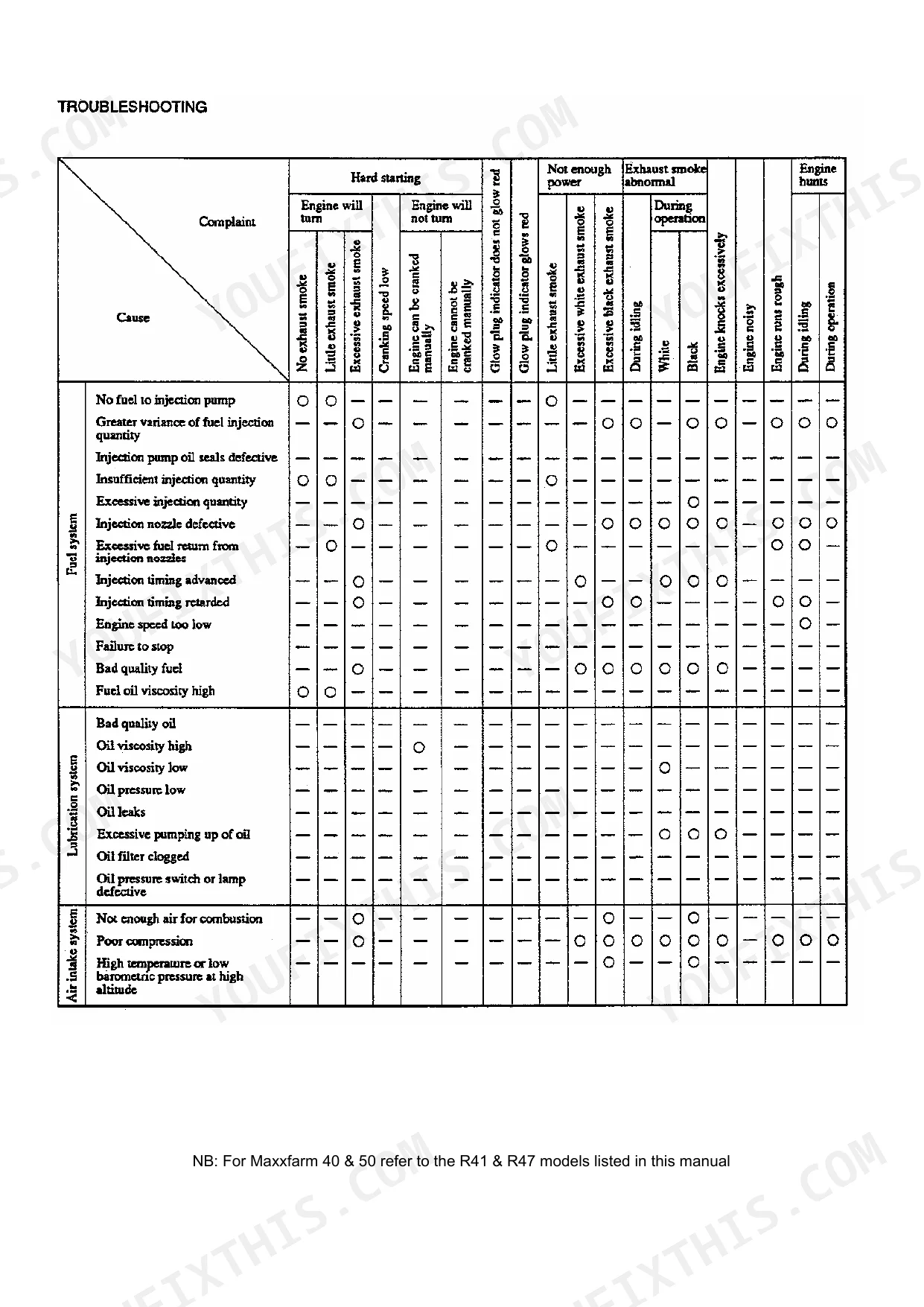
| Troubleshooting | 101-107 | Fuel System Complaints (No Fuel to Injection Pump, Greater Variance of Fuel Injection Quantity, Insufficient Injection Quantity, Excessive Injection Quantity, Injection Nozzle Defective, Excessive Fuel Return From Injection Nozzle, Injection Timing Advanced, Injection Timing Retarded, Engine Speed Too Low, Failure to Stop, Bad Quality Fuel, Fuel Oil Viscosity High) |
| Maintenance Standards | 108-113 | Engine Oil Pressure, Fuel Injection Timing, Valve Timing, Warpage of Top Face, Valve Stem Clearance, Rocker Arm Clearance, Crankshaft Journal Diameter, Crankpin Diameter |
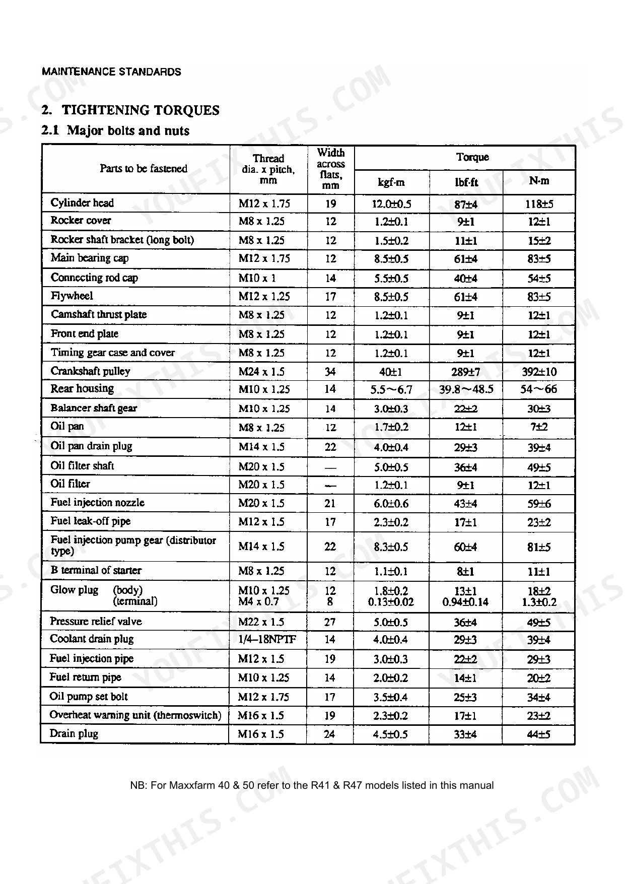
| Tightening Torques | 114-115 | Major Bolts and Nuts, Standard Bolts, Standard Studs, Standard Plugs |
| Thread Sealants | 116 | Cylinder Head Coolant Hole Plug, Crankcase Coolant Hole Plug, Crankcase Oil Gallery Plug, Crankcase Oil Return Pipe, Crankcase No. 1 and No. 5 Bearing Cap Grooves |
| Maintenance Schedule | 117 | Walk-Around Inspection, Valve Clearance, Cylinder Head Bolts, Oil Pan, Oil Filter, Fuel Injection Nozzles, Radiator, Fan Belt |
| Special Tools | 118-119 | Valve Spring Pusher, Valve Guide Remover, Valve Guide Installer, Valve Seat Insert Caulking Tool, Stem Seal Installer, Idler Gear Bushing Installer, Idler Gear Shaft Puller |
| Transmission | 120-162 | General Notices, Notices in Assembling, Power Transition, Dimension (Mechanical) |
Quick Reference Specifications
| Specification | Value | Page |
|---|---|---|
| Steering Unit O-ring (I.D.) | Ø47.2 x Ø3.5 | p. 203 |
| Thermostat valve start opening temperature | 76.5±1.5°C (170±2.7°F) | p. 74 |
| Thermostat valve full lift temperature (lift > 8mm) | 90°C (194°F) | p. 74 |
| Fuel filter replacement interval | Every 500 service hours | p. 79 |
| Glow plug current | 4.4A, approx. (15 second rating) | p. 99 |
| Glow plug voltage | 22V | p. 99 |
| Firing order | 1-3-4-2 | p. 5 |
| Flywheel tightening torque | 8.5±0.5 kgf·m | p. 31 |
| Alternator voltage reading (at 20°C) | 14.7±0.3 V | p. 221 |
| Fuel solenoid pull coil current | 50A | p. 227 |
| Glow plug resistance | 0.55Ω | p. 228 |
| Front axle gear oil amount | 10 ℓ | p. 188 |
Case IH MaxxFarm 40-50 Common Problems This Manual Covers
Case IH Maxxfarm 40 engine hard to start in cold weather, cranks slowly or not at all
Check each glow plug with a multimeter — resistance should read 0.55Ω per plug (page 228). If a plug reads open or significantly higher, replace it. Verify glow plug current draw at 4.4A per plug during the 15-second preheat cycle (page 99). Inspect battery voltage under load; a weak battery won't sustain the starter draw needed for cold diesel ignition.
Manual Section: Electrical System p. 99Engine overheats, coolant full but temperature gauge climbs to red
Remove the thermostat and test it in a water bath with a thermometer: it must begin opening at 76.5±1.5°C (170±2.7°F) and reach full lift above 8mm at 90°C (194°F) per page 74. If the thermostat fails to open or does not reach the specified lift, replace it.
Manual Section: Cooling System p. 74Frequently Asked Questions
What are the torque specs for the engine bolts on Case IH Maxxfarm 40?
The manual provides specific torque specifications for various engine bolts. For instance, the cylinder head bolts (M12 x 1.75) should be tightened to 12.0±0.5 kgf·m (87±4 lbf·ft) or 118±5 N·m. The connecting rod cap bolts (M10 x 1) require a torque of 5.5±0.5 kgf·m (40±4 lbf·ft) or 54±5 N·m. p. 114
What are the torque specs for the axle mounting bolts on Case IH Farmall R47?
The torque specifications for front axle bolts vary by component. For example, the fixing bolt for the knuckle arm should be tightened to 9.5 ~ 11.0 kgf·m. The reamer bolt requires a torque of 13 ~ 15 kgf·m, and the fixing bolt for the king pin case should be tightened to 12.0 ~ 13.5 kgf·m. p. 183
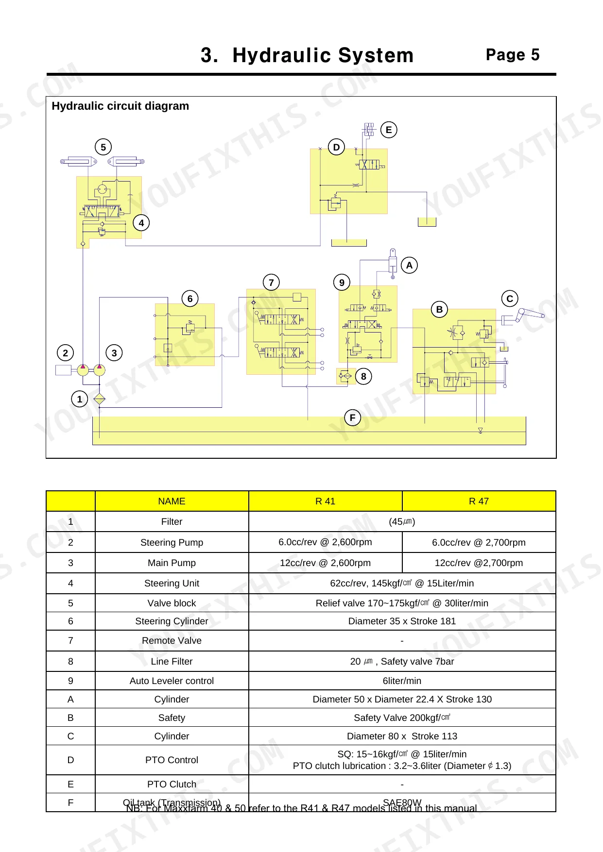
What are the replacement specifications for O-rings for hydraulic stacks?
The manual provides O-ring specifications for the steering unit, which is a hydraulic component. These include O-rings with an inner diameter (I.D.) of Ø47.2x Ø3.5, Ø9.3xØ1.8, and Ø7.6xØ1.8. When installing, ensure to use the correct size for the specific location, such as the two O-rings (I.D: Ø7.6 X Ø9.0) on the check seat. p. 203
What are the replacement specifications for Thermostat?
The thermostat specifications indicate that the valve should start opening at 76.5±1.5°C (170±2.7°F). The valve lift should be more than 8 mm (0.3 in.) at 90°C (194°F). If the thermostat does not open to the correct lift, it should be replaced.
What do I get after purchasing this Case IH Maxxfarm 40 & variants?
A 230-page Service Manual in searchable PDF format, available the moment you complete checkout. View on computer, tablet, or phone, with no shipping wait.
Is this Case IH Maxxfarm 40 & variants Service Manual printable?
The PDF is DRM-free. Print whatever sections you need to take out to the shop. Standard letter or A4 paper works.
Can I find wiring schematics in this Case IH Maxxfarm 40?
Yes, full electrical schematics are included with wire colors, connector locations, and circuit descriptions.


Reviews
There are no reviews yet.