


All 254 pages of this CNH F5 Series Repair Manual PDF (OEM #87736548A) cover five engine variants from one factory source: F5AE9484, F5AE9454, F5CE9484, F5CE9454, and F5CE5454. Inside you get wiring diagrams for the complete electrical system, full system diagrams routing lubrication, cooling, EGR, and fuel supply, plus a dedicated troubleshooting section and detailed clearance data and torque tables for every major assembly. Exploded views walk you through cylinder unit teardown, timing system, valves, valve guides, and engine drive shaft work. Pre-tighten the injector fastening nut to 15 ± 5 Nm, torque the stud screws to 25 ± 4 Nm, and set injector protrusion to 1.7–2.35 mm. No more chasing engine faults with nothing but forum threads and guesswork. Bookmarked by section; pull it up on any device and jump straight to the spec you need.
What's Inside This CNH F5 Series Repair Manual
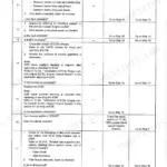
| System | Pages | Key Topics |
|---|---|---|
| Repair Instruction Manual | 1-2 | Preface to USER’S Guideline Manual, Symbols, Warnings, Service Operations, General Warnings, Optional Electrical and Mechanical Parts Installations |
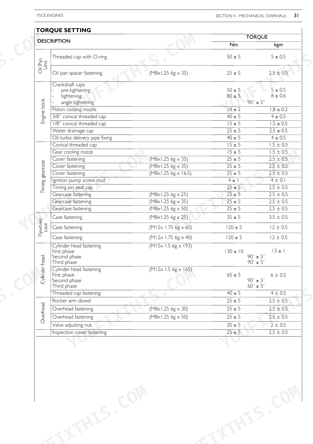
| Special Remarks | 5-6 | Housing for Connecting Rod Small End Bush, Housing for Connecting Rod Bearings, Tighten to Torque, Tighten to Torque + Angular Value |
| Introduction | 7-16 | Prefacetouser’Sguidelinemanual, General Warnings, General Warningson the Electricsystem, Bonding and Screening, Optional Electrical |
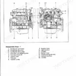
| F5Ae Engines | 141-142 | Technical Coding, Engine Views, Lubrication, Oil Pump, Counterotating Mass Balancing Device, Engine Oil Filter |
| General | 143-158 | Technical Coding, Engine Views, Lubrication, Oil Pump, Engine Oil Filter, Engine Oil Vapour Recirculation, Coolingsystem, Water Pump |
| Supply | 159-170 | Pipe Layout, Supply Pump, Working System Description, L.D.A. Load Delivery Adjustment Device, Priming Pump, Fuel Filter |
| Industrial Appliance | 171-212 | Main Specifications, Part One -Mechanical Components, Part Two - Electrical Equipment, Part Three - Diagnosis, Part Four Scheduled Maintenance |
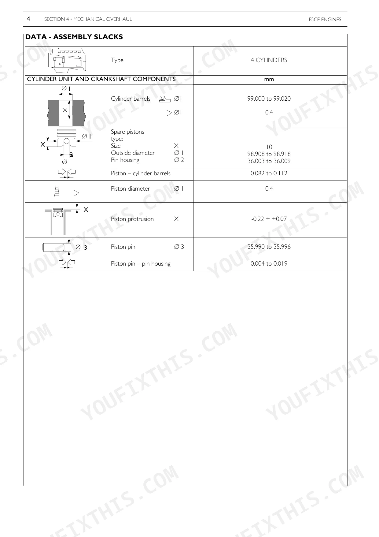
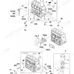
| Mechanical Overhaul | 213-244 | General Specifications, Engine Overhaul, Repairs Cylinder Unit, Timing System, Engine Drive Shaft, Valves, Valveguide, Valvesprings |
| Tools | 245-252 | - |
Quick Reference Specifications
| Specification | Value | Page |
|---|---|---|
| All Models | ||
| Nozzle type | BOSCH DSLA138PV 33 | p. 99 |
| Injector protrusion | 1.7 to 2.35 | p. 104 |
| Condition for replacement (Obstructed fuel pipes) | Disassemble the pipes, clean them and replace those that are seriously dented. | p. 90 |
| Condition for replacement (Incorrect ignition pipe internal diameter, dented pipe ends due to repeated locking) | Check the conditions of the pipe ends or pipe fittings and eventually replace the pipes. | p. 92 |
| L.D.A. device counter spring condition | Check that the counter spring is appropriate and correctly loaded (test on bench). | p. 90 |
| Cylinder unit processing caps condition | Replace them if oxidized or in case their tight is doubtful. | p. 107 |
| Cylinder head base surface processing caps condition | Replace them if oxidized or in case their tight is doubtful. | p. 108 |
| Intake manifold pressure check (Defective L.D.A. device) | Check the pressure within the intake manifold is correct in relation to the engine speed at full load. | p. 90 |
| Engine Oil Pump Feed Pressure | 2 Bar - 4 Bar | p. 28 |
| Engine Oil Filter Torque Setting | 18 ±2 Nm | p. 29 |
| F5CE5454B | ||
| Injection pump static advance control on engine at cylinder 1 TDC (61 kW engines) | 1 ± 0.05 mm | p. 70 |
| F5CE9454E | ||
| Injection pump static advance control on engine at cylinder 1 TDC (55 kW engines) | 0,88 ± 0.05 mm | p. 70 |
CNH F5 Series Common Problems This Manual Covers
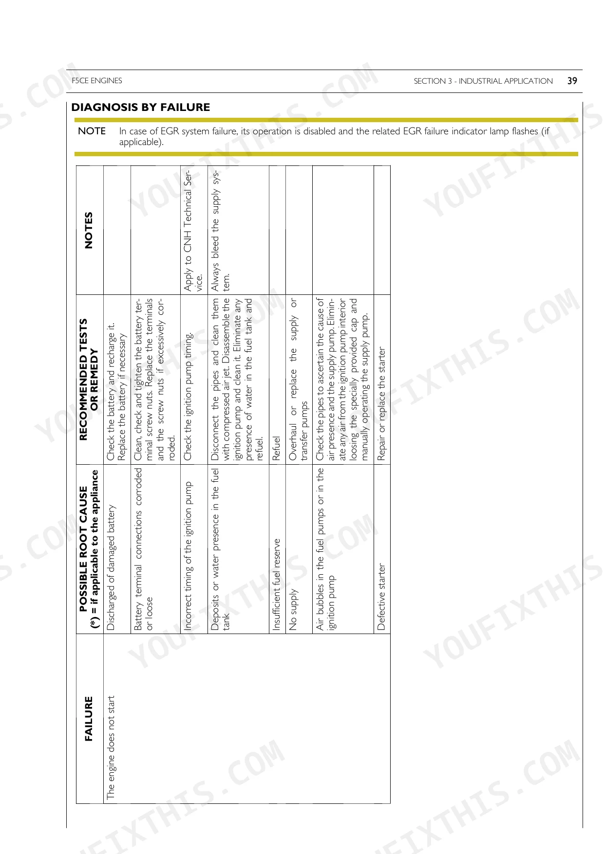
Engine cranks but won't fire or turns over very slowly in cold weather
Check the K.S.B. cold-start device for full engagement and verify no fuel system obstruction is present. Confirm the fuel filter is clean and the priming pump builds adequate delivery pressure. After the engine fires, confirm idle stabilizes at 1150 ± 50 rpm (page 51) before applying any load.
Manual Section: Engine does not start at low temperaturesEngine bogs under throttle, fuel delivery inconsistent, injector pipes obstructed or dented
Disassemble the fuel pipes and blow each line clear with compressed air. Replace any pipe with serious deformation, especially at the ends from repeated locking (page 90). Inspect all pipe fittings and replace where the internal bore is reduced (page 92). After reconnecting, prime the system and verify idle holds steady at 1150 ± 50 rpm (page 51).
Manual Section: Insufficient engine power and irregular functioning p. 90Engine temperature climbs above normal range, coolant boiling or steam from overflow
Inspect the water pump drive belt for slippage and check coolant level before anything else. Bench-test the thermostat; stroke should begin at 79° ± 2°C (page 32). If the thermostat passes, flush the cooling passages for scale buildup and check the air filter for restriction. Correct injection timing per the diagnostic index if overheating persists.
Manual Section: Engine excessively heats up p. 32Coolant loss with no visible crack, block processing caps oxidized or loose
Remove the cylinder unit and inspect all processing caps for surface oxidation or seating failure (page 107). Check the cylinder head base surface caps as well and replace any that are oxidized or show doubtful sealing (page 108). After fitting new caps and reassembling, torque cylinder head fasteners to 130 ± 10 Nm for the first phase (page 127).
Manual Section: Mechanical Overhaul p. 107Frequently Asked Questions
How to adjust ignition pump setting for correct spark lead angle on F5AE9484
To adjust the ignition pump setting for the correct spark lead angle on the F5AE9484 engine, use a dial gauge (380000228) and holder (380000229) with a 2.5 mm preloading rod. The dial gauge should display 0,76 ± 0,05 mm for 48 kW, 57 kW, 65 kW engines, or 0,88 ± 0,5 mm for 55 kW engines. Rotate the pump anticlockwise or clockwise until the required run is achieved, then lock the pump and related nuts at the predefined torque. p. 192
What are the replacement specifications for Injectors?
For F5CE and F5AE engines, the nozzle type for injectors is BOSCH DSLA138PV 33. When fastening injectors, the injector fastening nut requires a pre-tightening torque of 15 ± 5 Nm (1.5 ± 0.5 kgm) and a final tightening torque of 30 ± 5 Nm (3 ± 0.5 kgm) for F5CE models, or 30 ± 2 Nm (3 ± 0.5 kgm) for F5AE models. p. 128
How do you fix CNH F5 engine injection pump timing off after service, insufficient power and irregular ignition?
Bring cylinder 1 to TDC and measure static pump advance with a dial gauge. F5AE engine plunger lift targets 0.76 ± 0.05 mm (page 192); F5CE variants: confirm your spec on page 70. After adjusting, torque the pump gear pre-tighten to 18 ± 2 Nm, then final to 90 ± 5 Nm (page 129).
How do you fix engine misfires and loses power under load, nozzles fouled or worn?
Remove the BOSCH DSLA138PV 33 nozzles and bench-test each for spray pattern and opening pressure (page 99). Check injector protrusion after reinstall; it must fall between 1.7 and 2.35 mm (page 104). Torque the fastening nuts to 30 ± 2 Nm on F5AE9484/F5AE9454 (page 242) or 30 ± 5 Nm on F5CE models (page 243). p. 99
What do I get after purchasing this Cnh F5 Series manual?
Immediate download of the complete 254-page searchable Repair Manual. Access it on any device, from a laptop at your desk to a phone in the field.
Am I able to print pages from this Cnh F5 Series manual?
Yes, print as many copies as you want, and there are no restrictions. Many mechanics print the section they need and bring it to the shop floor.
Does this Cnh F5 Series Repair Manual have electrical diagrams?
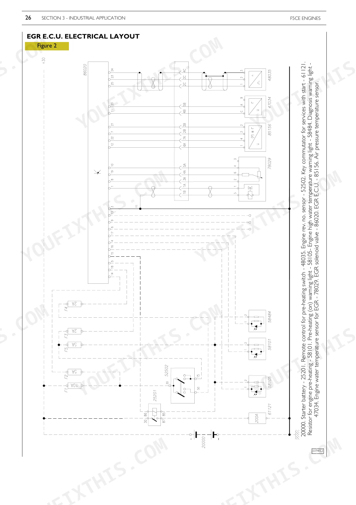
Yes, full electrical schematics are included with wire colors, connector locations, and circuit descriptions.
Reviews
There are no reviews yet.