


![Fiat 466, 566, 666, 766 Repair Manual [Tractor]](https://youfixthis.com/wp-content/uploads/2013/10/YouFixThis_Traktor_Screen_2_S-300x300.jpg)
Complete Workshop Repair Manual Fiat agri 115-90 130-90 140-90 Tractor. Detailed Step by Step Instructions, diagrams, illustrations make easy any repair, Overhaul, Disassembly and Assembly, Testing and Tuneup, Replacement and Change, Inspection and Adjustment.
= Printable
= Zoom able
= Clickable index
= Bookmarks
= Searchable Text
MODELS Covered
Fiat Tractor
115-90
130-90 Turbo
140-90 Turbo
SECTIONS covered
* Index
* Section
* General
* Specification
* Engine
* Powertrain
* Front Axle — Steering
* Front Wheel Drive (Dt)
* Hydraulic Lift Unit
* Electrical System
* Service Tools
GENERAL
General instructions
Safety
SPECIFICATIONS
Identification data – Weights
Engine
Power Train – Brakes – Steering
Front axle • Front wheel drive – Rear wheels – Power take-ott – Lift
Towing attachments – Ballasting – Body
Electncal system – Lighting – Instrument and accessories – Tire sizes
Mod 115-90H
Main Dimension
Power train schematics
Ricefield version tractors
Mods. 160-90 Turbo and 160-90 Turbo
Late mod, engine
ENGINE: Specifications and data
Engine block – Cylinder head
Crank Gear
Velve Gear
Lubriacation system
Cooling system
Fuel system
Torque data
Faseners
Engine sections
ENGINE: Description
Engine performance data
Turbocharged engine performance test
Compression Test
Removal – Installation
ENGINE: Engine block – Cylinder head
Cylinder liners
Cylinder head
Oil pan
ENGINE: Valve gear
Camshaft – Valves, guides and springs
Tappets, pushrods and rockers
Valve gear train
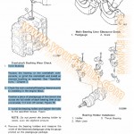
ENGINE: Crankgear
Crankshaft
Main and big end bearings and caps
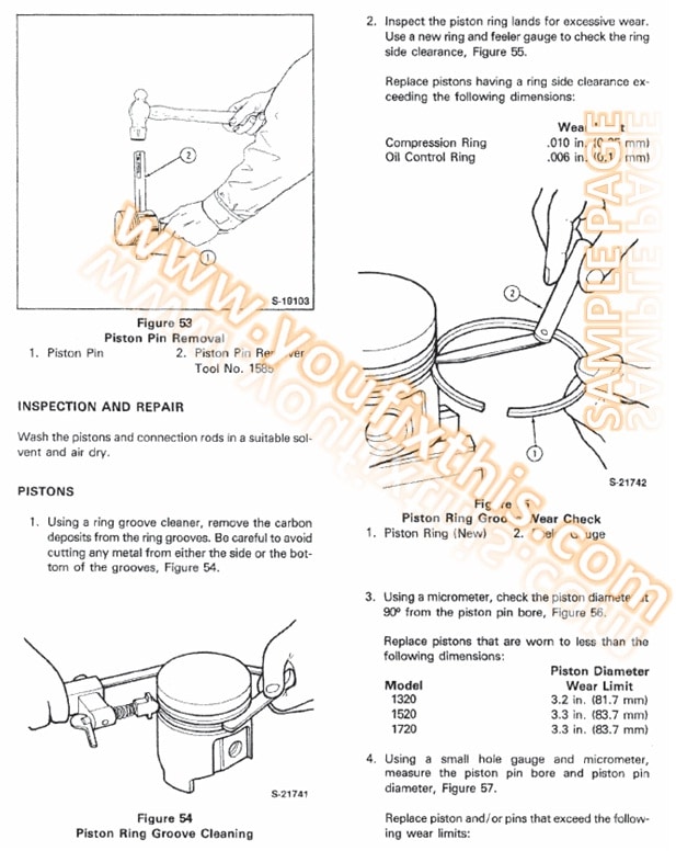
Pistons and rings
Connecting rods
Flywheel
ENGINE: Fuel system
Air Cleaner
Fuel titters
Youfixthis.com
Turbocharger components
Turbocharger: Description and operation – General
GARRETT turbocharger service
HOLSET turbocharger service
Turbocharger trouble shooting
ENGINE: Lubrication system
Lubrication system diagram
Oil pump – Oil filter
Heat exchanger – Low oil pressure indicating system
Pump removal and replacement
Removal a n d replacement
ENGINE: Cooling system
Cooling system diagram
Description – Water pump
Radiator
Belt tension ad|ustment – Water temperature gauge – Thermostal
Water pump – Late Mods
Turbo
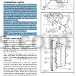
POWER TRAIN: Specifications and data
Clutch
Transmission and splitter
POWER SHIFT transmission
Creeper
Reverser
Rear bevel drive and differential
Brakes
Power take-off
Torque data
Longitudinal and cross sections through
powertrain
Power train cross section
Late Model master clutches
FronlP.T.o
Late Model P.T.O. clutch
POWER TRAIN: Removal and installation
Platform removal and installation
Platform removal and installation together with FIAT cab
POWER TRAIN: Master clutch
Removal and installation
VALEO clutch service
VALEO clutch adjustment
LUK 12712″ clutch service
LUK 12712″ clutch adjustment
Clutch linkage adjustment
Section through VALEO clutch
Section through LUK clutch
LUK 12″ + 12″ clutch service
LUK 12″ + 12″ clutch adjustment
Master clutch hydraulic control
VALEO 12″/12″ clutch service
VALEO 12712″ clutch late Models
OMG 12712″ clutch service
OMG 1Z712″ clutch service
POWER TRAIN: Transmission and Splitter
Removal and installation
Disassembly
Inspection – Assembly
Longitudinal and cross sections through transmission and splitter
Transmission lubrication circuil
POWER TRAIN: POWER SHIFT transmission
Removal and installation
Disassembly
Clutch B service
Longitudinal and cross sections through
POWER SHIFT transmission
Clutch C (or D) service
Control valve service
Accumulator service
Sections through control valve and accumulators 26
Assembly
Installation – Hydraulic test
Hydraulic tests
Drive shaft bearing replacement
Transmission and steering pump
Hydraulic system schematics
Transmission and control valve modifications
POWER TRAIN: Creeper Mechanical reverser
Creeper Descnption – service
Mechanical reverser: Descnption vice
Creeper and reverser linkage adjustment
POWER TRAIN: Bevel drive and differential
Removal
Removal and installation – Bevel drive and differential (mechanical differential lock version)
Removal and installation – Bevel drive and differential (hydraulic differential lock version)
Bevel pinion shaft removal and installation
Longitudinal and cross sections through bevel drive and differential
Bevel drive adjustment
Differential pinion and side gear backlash adjjstment
Mechanical differential lock assembly and adjustmenl
Mechanical differential lock pedal adjustment
Hydraulic differential lock pedal adjustment
Hydraulic differential lock – Removal and installation
Hydraulic differential lock – Circuit pressure test
Hydraulic pump
Hydraulic differential lock schematics
POWER TRAIN: Brakes
Hydraulic system operation
Brake unit assembly and disassembly
Master cylinder assembly and disassembly
Brake pedal adjustment
Brake pedal installation – Brake system bleeding
Master cylinder bench test
Parking brake
Parking brake lever adjustment
POWER TRAIN: Final drives
Removal
Assembly
Side final drive units with twin wheels
Double-flange side final drives
POWER TRAIN: Power take-off
Removal and installation
Disassembly and assembly
Longitudinal section through PTO
PTO hydraulic clutch removal and installation
PTO hydraulic clutch pressure relief valve
setting check
Hydraulic pump – service
PTO hydraulic operation schematics
Front power take-off
Late PTO hydraulic clutch
Front PTO; Removal and installation
Hydraulic system schematics
FRONT AXLE – STEERING: Specifications and data
Front axle
Power steering
Torque data
FRONT AXLE – STEERING: Front axle
Removal and installation – Steering knuckle service
Axle check
FRONT AXLE – STEERING: Power steering
Power steering service
Hydraulic cylinder service
Power steering checks
Power cylinder pressure relief/safety valve setting
Hydraulic system operation schematics
and sections
Trouble-shooting chart
Hydraulic pump service
Output test
FRONT WHEEL DRIVE: Specifications and data
Live front axle – Early Models
Live front axle – Late Models (50° – steer)
Axle drive – Mechanical
Axle drive – Electrohydraulic
Torque data
FRONT WHEEL DRIVE; Live front axle
Early models; Removal – Final drive; wheel hub and steenng knuckle service
Early models: Bevel dnve adjustment and service
Early models: Differential hydraulic lock clutch service
NO-SPIN differential
Late models: Differential hydraulic lock clutch service
Late models: Removal – Final drive, wheel hub and steering knuckle service (50° – steer)
Late models: Bevel drive adjustment and service (50° – steer)
FRONT WHEEL DRIVE: Drive shafts – Axle drive
Drive shaft disassembly a n d assembly
Mechanical axle drive removal, disassembly, adjustment, assembly and installal
Early model axle sections
Late model axle sections (50″ – steer)
Electro-hydraulic axle drive removal, disassembly, adjustment, assembly and installation
HYDRAULIC LIFT UNIT: Specifications and data Lift
Lift pump
Implement attachment
Auxiliary cylinder
Remote control valves
Tornue data
Trailer brake control valve trouble shooting chart
Lift trouble shooting chart
Electronically controlled lift
HYDRAULIC LIFT UNIT: Lift
Removal – Disassembly
Inspection
Assembly
Liftadjustments
Lift control linkage adjustments
Control valve assembly with LIFT-O-MATIC
Valve checks
Hydraulic system schematics
Opiration
Electronically controlled lift
Removal – Disassembly
Front lift
Operation schematics
Description – Operation stages
Disassembly – Assembly – Adjustment
HYDRAULIC LIFT UNIT: Lift pump
Service
Output test
HYDRAULIC LIFT UNIT: Implement attachment
Three point linkage – Right-hand lifting rod .
Draft control device
Three point linkage with hydraulic adjustment
HYDRAULIC LIFT UNIT: Remote control valves
Description and operation
Hydraulic system diagrams
Disassembly
Relief valve adjustment
Spool return test
Remote control valve leakage test
Trailer brake remote control valve
Description
Hydraulic system diagram
ELECTRICAL SYSTEM – Specifications and data
Charging system – Battery – Lighting – Signals – Accessories
MARELLI starter
BOSCH starter
Fuses – Switches
Control and instruments
Control operation
Wiring diagram
Data monitor panel operation check
SERVICE TOOLS
Reviews
There are no reviews yet.