


This Gehl service manual covers the SL7600 and SL7800 skid steer loaders (Gehl form number 908275), powered by the Yanmar 4TNE106 and 4TNE106T diesel engines. It runs 205 pages with a full text layer and factory bookmarks for quick navigation.The manual guides you through assembly and disassembly, removal and installation, adjustment, testing, and troubleshooting across every major system: mainframe, wheel drives, controls, the hydrostatic drive, the hydraulic system, electrical, and the engine. Specifications and lubrication sections list horsepower, capacities, and torque values up front.With it you can diagnose slow or drifting lift and tilt, test hydrostatic charge pressure, service the drive chains and axles, replace the hydraulic oil filter element, and rebuild cylinders correctly. It downloads as a PDF you can print or search on any device.
What's Inside This Gehl SL7600, SL7800 Manual
| System | Pages | Key Topics |
|---|---|---|
| Specifications | 8-9 | Dimensional Specifications |
| Safety | 10-17 | - |
| Lubrication | 18-21 | Safety Reminders, Hydraulic Oil Reservoir, Crankcase Oil, Chaincases, Grease Fitting Locations, Cooling System Drain Procedures (Additional Safety Reminders, Signal Words) |
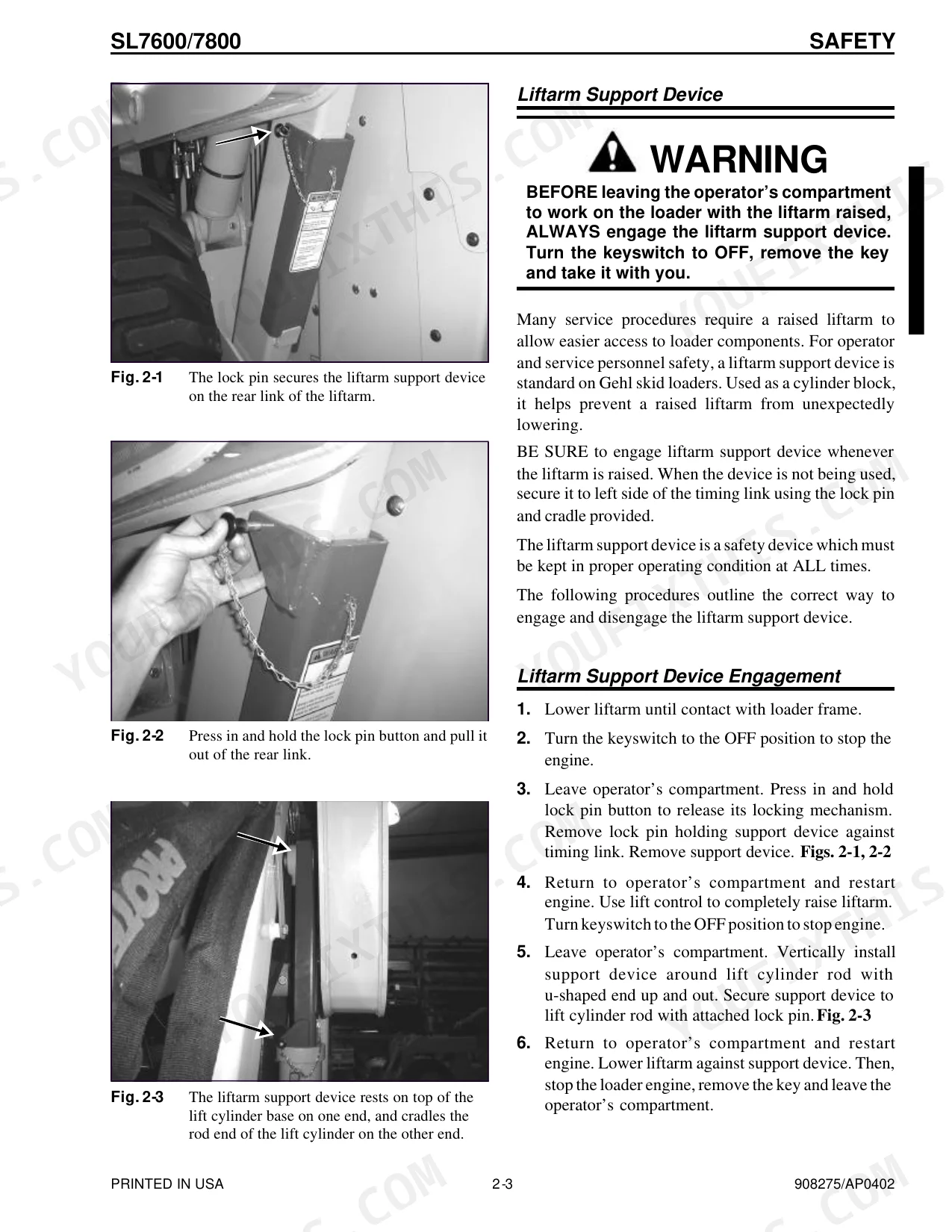
| Mainframe | 22-47 | Engine Access Covers - Removal and Installation, ROPS, Raising (Liftarm Support Device Disengagement), Rollover Protective Structure Removal and Installation, Lowering |
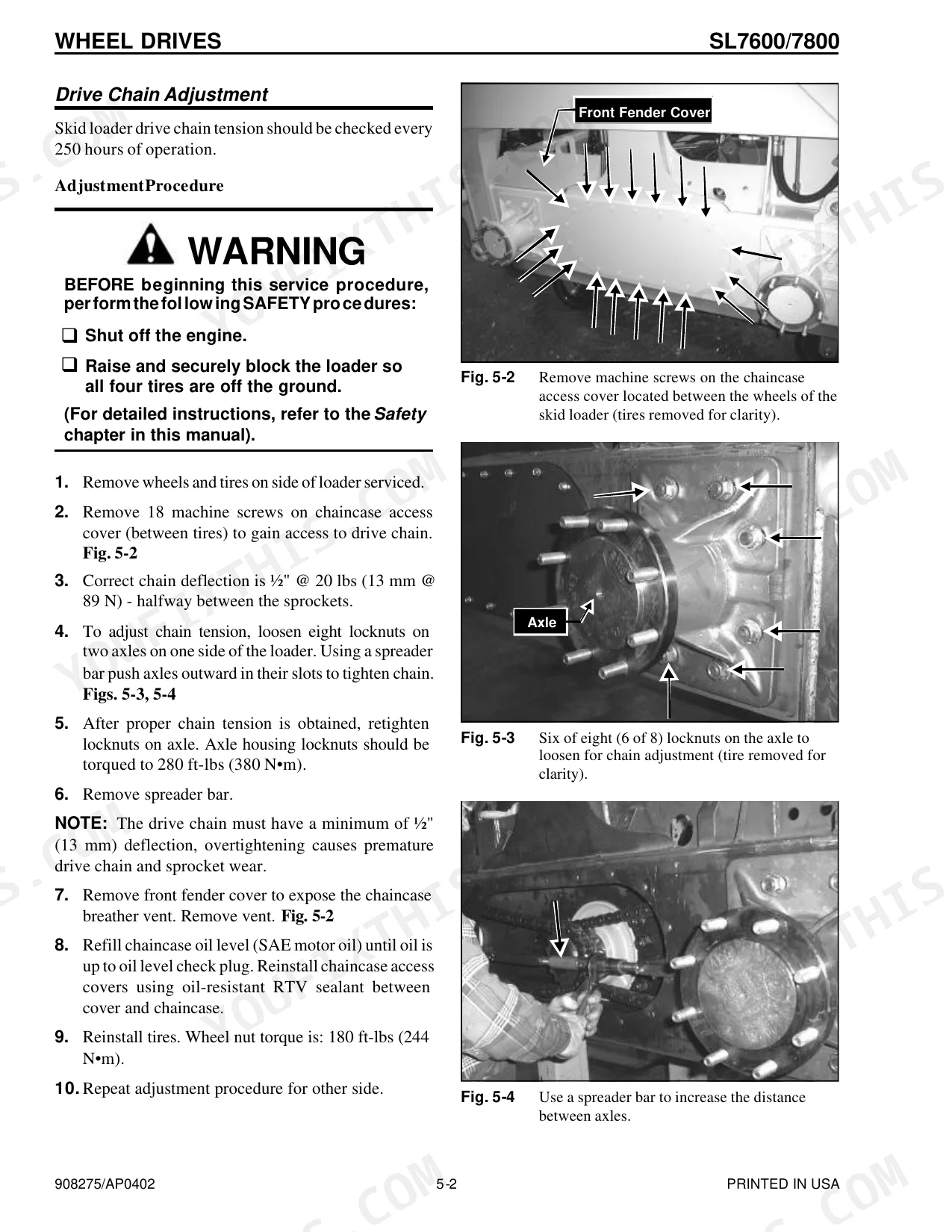
| Wheel Drives | 48-55 | Restraint Bar Components, Drive Chain Adjustment, Hitch Removal and Installation, Axle Housing Assembly Removal and Installation, Drive Chain Removal and Installation |
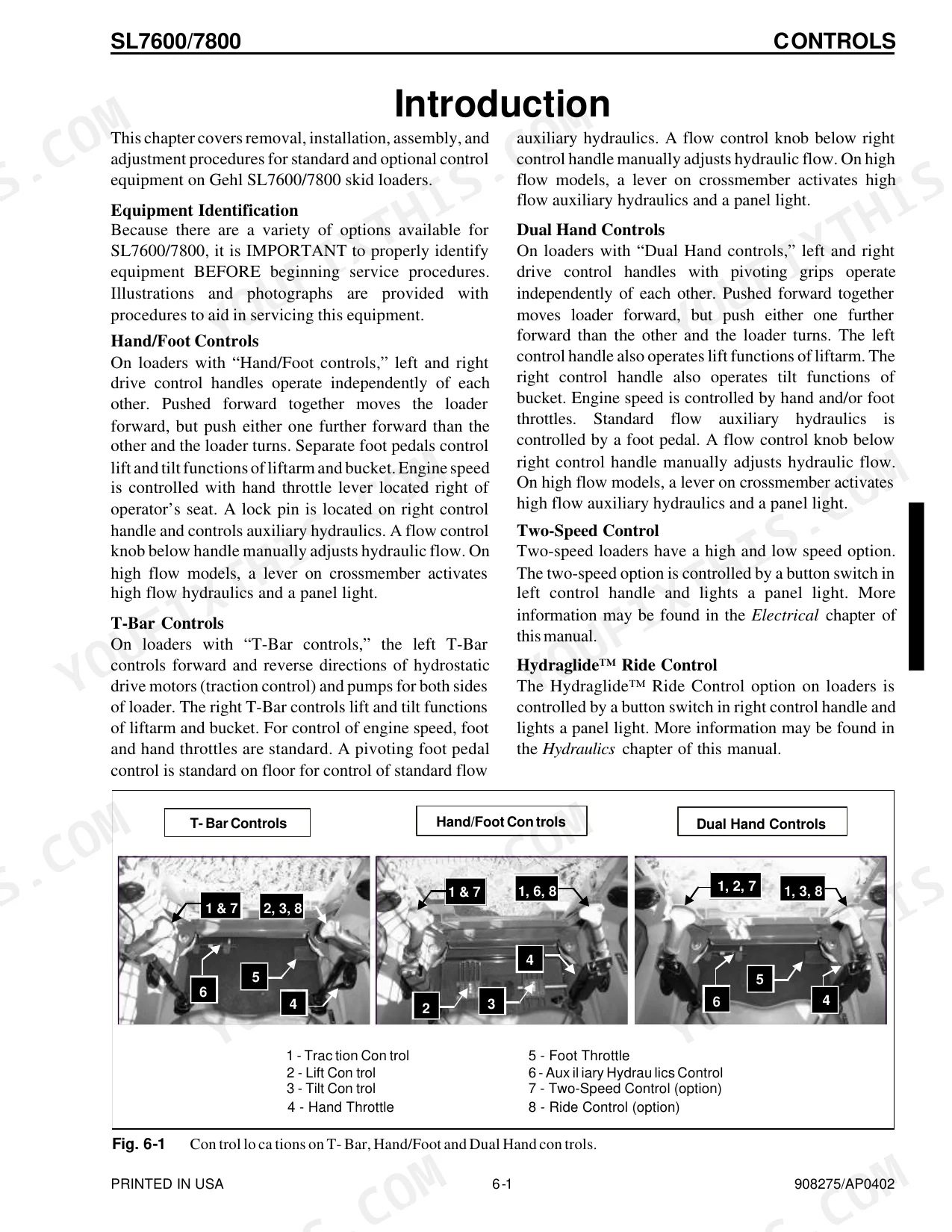
| Controls | 56-91 | Control Handle Removal and Installation, Control Handle Position Adjustment, T-Bar Control Models - Lift and Tilt, Control Handle Tracking Adjustment |
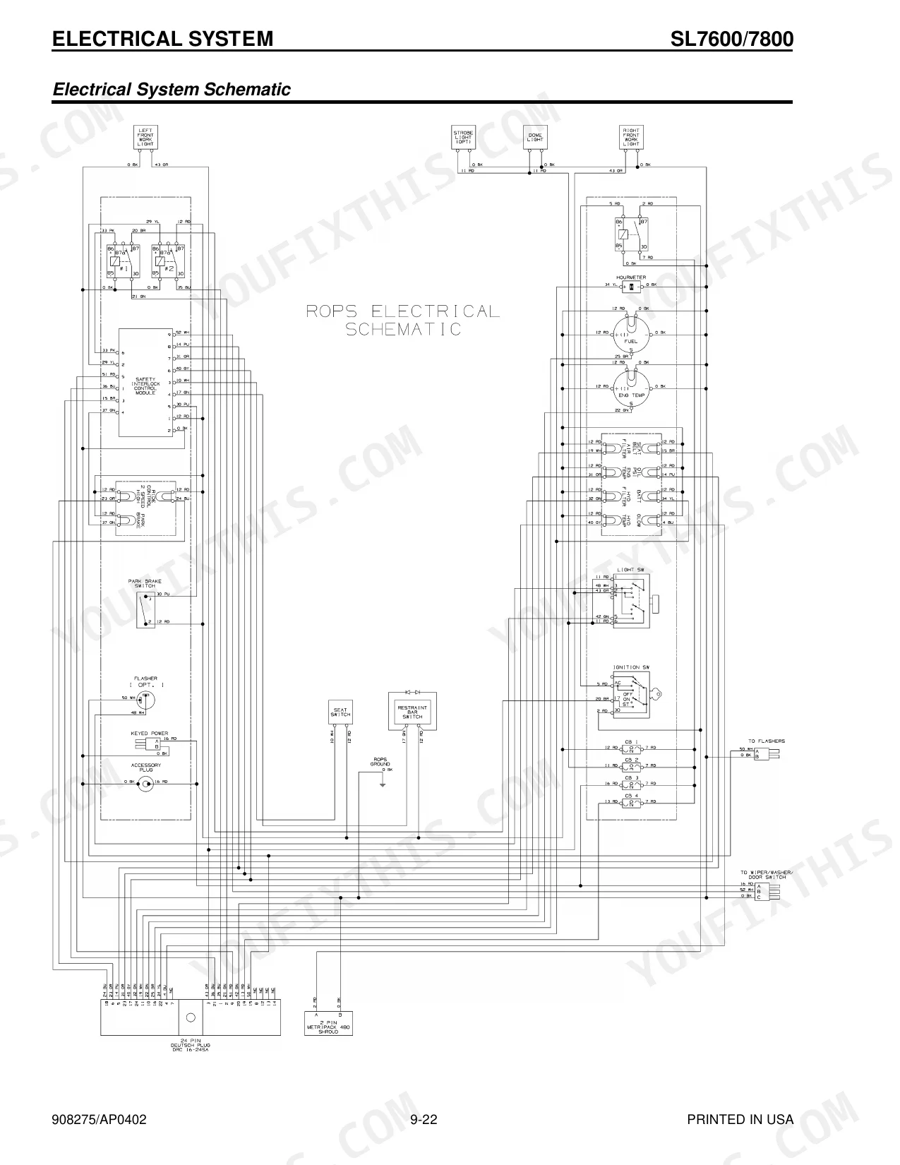
| Hydrostatic System | 92-103 | ROPS Electrical Components (Module and Relay Test and Operation), Module and Relay, Power Relay, Starter Relay, Hydrostatic Pump Removal / Installation, Horn Relay |
| Hydraulic System | 104-149 | Tilt Cylinder Test, Self-Leveling Valve Test, Lift Cylinder Test, Solenoid Valve Test - Safety Lock, Brake and Two-Speed, Hydraulic Oil Filter Element Replacement |
| Electrical System | 150-173 | Operation - Right and Left Instrument Panels, Interlock Control Module Truth Table, Seat Switch Removal and Installation, Restraint Bar Switch Removal and Installation |
| Engine | 174-193 | Starter Removal and Installation, Exhaust Assembly Removal and Installation, Fan Belt Adjustment, Cooler Radiator Removal and Installation, Fan Shroud Removal and Installation |
Every system also includes introduction.
Quick Reference Specifications
| Specification | Value | Page |
|---|---|---|
| All Models | ||
| Axle housing locknuts torque | 280 ft-lbs (380 N•m) | p. 49 |
| Wheel nut torque | 180 ft-lbs (244 N•m) | p. 49 |
| Upper tilt cylinder pin capscrew torque | 80 ft-lbs (108 N•m) | p. 122 |
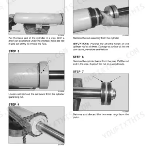
| Cylinder rod assembly locknut torque (head gland and piston) | 350 ft-lbs (474 N•m) | p. 127 |
| Hydraulic oil filter element replacement condition | when filter indicator on filter head shows red | p. 19 |
| Hydraulic oil filter element installation torque | hand tighten, then turn another 3/4 turn to seat gasket | p. 120 |
| Fan belt deflection | ½" (13 mm) under a load of 20 lbs (90 N) | p. 185 |
| Hydrostatic pump to flywheel housing capscrews torque | 55 ft-lbs (73 N•m) | p. 100 |
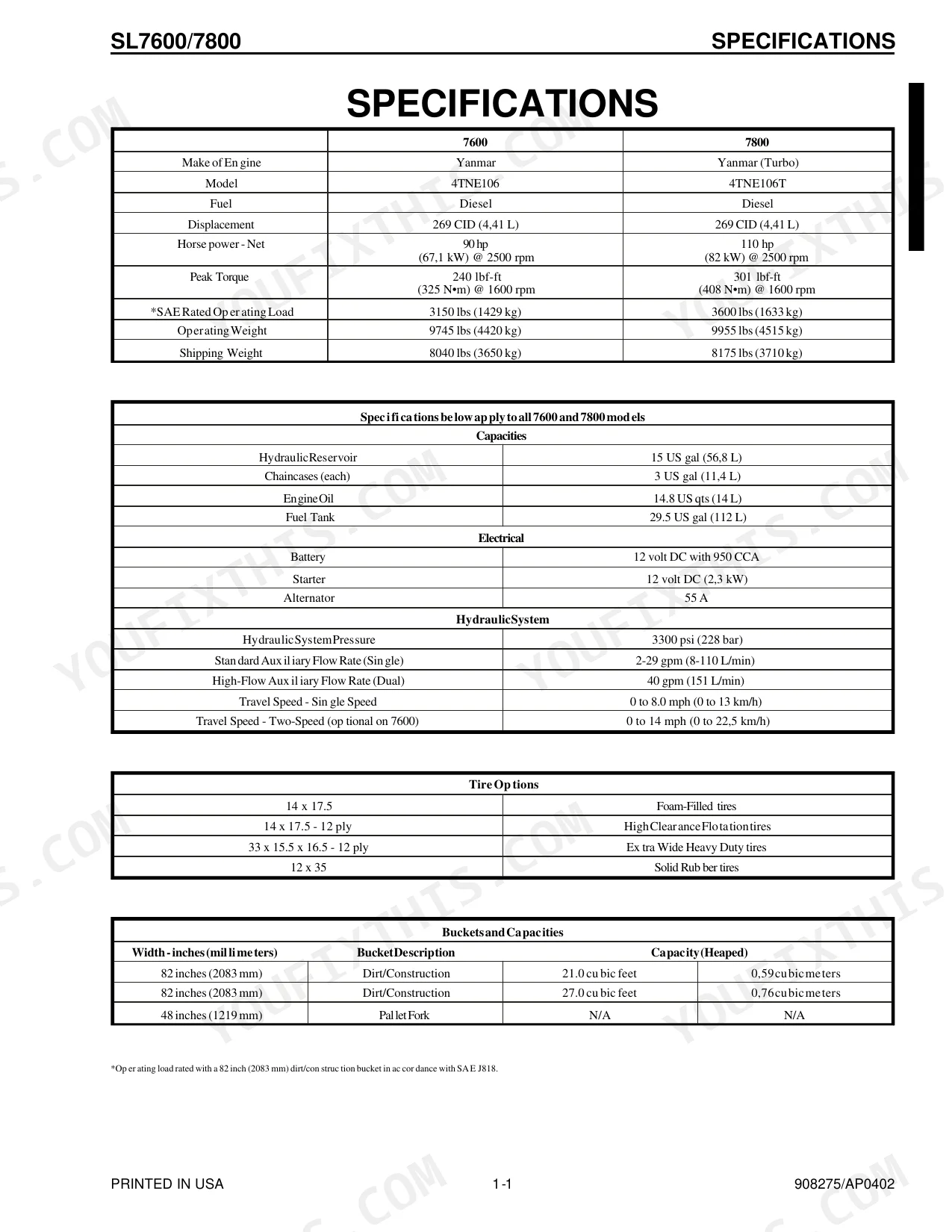
| Hydraulic Reservoir Capacity | 15 US gal (56.8 L) | p. 8 |
| Engine Oil Capacity | 14.8 US qts (14 L) | p. 8 |
| SL7600 | ||
| Engine Horsepower (Net) | 90 hp (67.1 kW) @ 2500 rpm | p. 8 |
| SL7800 | ||
| Engine Horsepower (Net) | 110 hp (82 kW) @ 2500 rpm | p. 8 |
Gehl SL7600, SL7800 Common Problems This Manual Covers
No start or cranks but will not run
A loader that cranks without firing, or will not crank, usually has a fault in the starting circuit, an interlock, or fuel and ignition supply. The Electrical System section covers the instrument panels, interlock control module, and the seat and restraint bar switches.
Manual Section: Electrical System p. 150Slow, weak, or unresponsive drive and lift
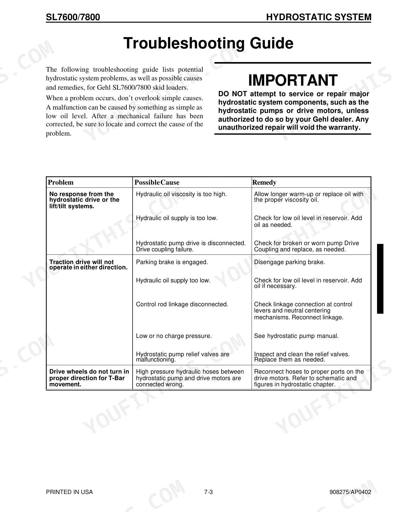
Drive or lift functions that feel weak point to hydraulic pump wear, low oil, clogged filters, or internal leakage. The Hydraulic System section covers tilt and lift cylinder tests, the self-leveling valve test, and hydraulic oil filter element replacement.
Manual Section: Hydraulic System p. 104Overheating or rising oil temperature
Excessive engine or hydraulic oil temperature often comes from restricted airflow, a dirty cooler or radiator, or a slipping fan belt. The Engine section covers fan belt adjustment plus cooler radiator and fan shroud removal and installation.
Manual Section: Engine p. 174Loader arms or bucket drift down
Attachments that settle when the controls are in neutral usually mean internal leakage in the lift or tilt cylinders or past control valve spools. The Hydraulic System section covers cylinder testing and the self-leveling valve test to confirm the leak.
Manual Section: Hydraulic System p. 104Will not steer or creeps in one direction
A machine that pulls to one side or creeps in neutral points to a hydrostatic drive issue such as charge pressure loss or a control linkage fault. The Hydrostatic System section covers charge pressure and hydrostatic pump service.
Manual Section: Hydrostatic System p. 92Drive chain stretch and axle wear
Loose drive chains and worn axle components cause wander and lost traction. The Wheel Drives section covers drive chain adjustment and removal along with axle housing assembly service.
Manual Section: Wheel Drives p. 48Frequently Asked Questions
Which machines and engines does this manual cover?
It covers the Gehl SL7600 and SL7800 skid steer loaders under form number 908275, powered by the Yanmar 4TNE106 and 4TNE106T diesel engines. The SL7600 is rated at 90 net horsepower and the SL7800 at 110, per the specifications.
Does it include torque specs for wheels and axles?
Yes. The Wheel Drives section covers drive chain and axle service, and the manual lists torque values such as the axle housing locknut and wheel nut figures alongside those procedures. p. 48
How do I check hydrostatic charge pressure?
The Hydrostatic System section gives the charge pressure range and covers hydrostatic pump removal and installation, so you can verify charge pressure before deciding whether the drive pump needs work. p. 92
How do I get the manual after purchase?
It is an instant digital download. After purchase you receive the PDF to save on your computer, tablet, or phone, with no waiting for a shipped copy.
Is this Gehl SL7600, SL7800 Service Manual a digital download?
This is a 205-page searchable PDF, and it downloads the moment you check out. Open it on a laptop, tablet, or phone and take it straight to the shop floor.
Is this Gehl SL7600, SL7800 Service Manual printable?
Yes. Print as many copies as you like; there are no restrictions. Plenty of mechanics run off just the section they need and keep it at the workbench.
Are hydraulic system diagrams in this Gehl SL7600, SL7800 Service Manual?
Included. Hydraulic system schematics cover all circuits, control valves, and component specifications for the Gehl SL7600, SL7800.


Reviews
There are no reviews yet.