
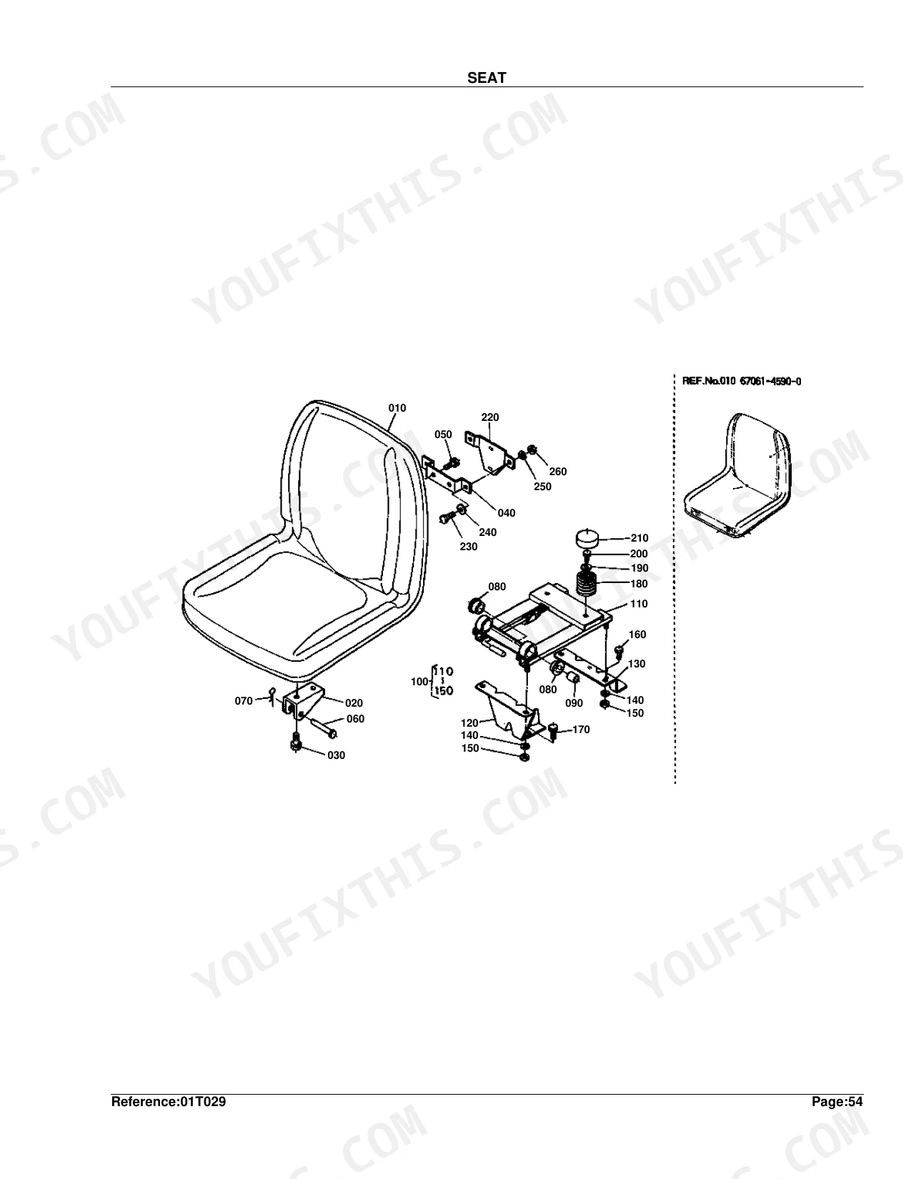
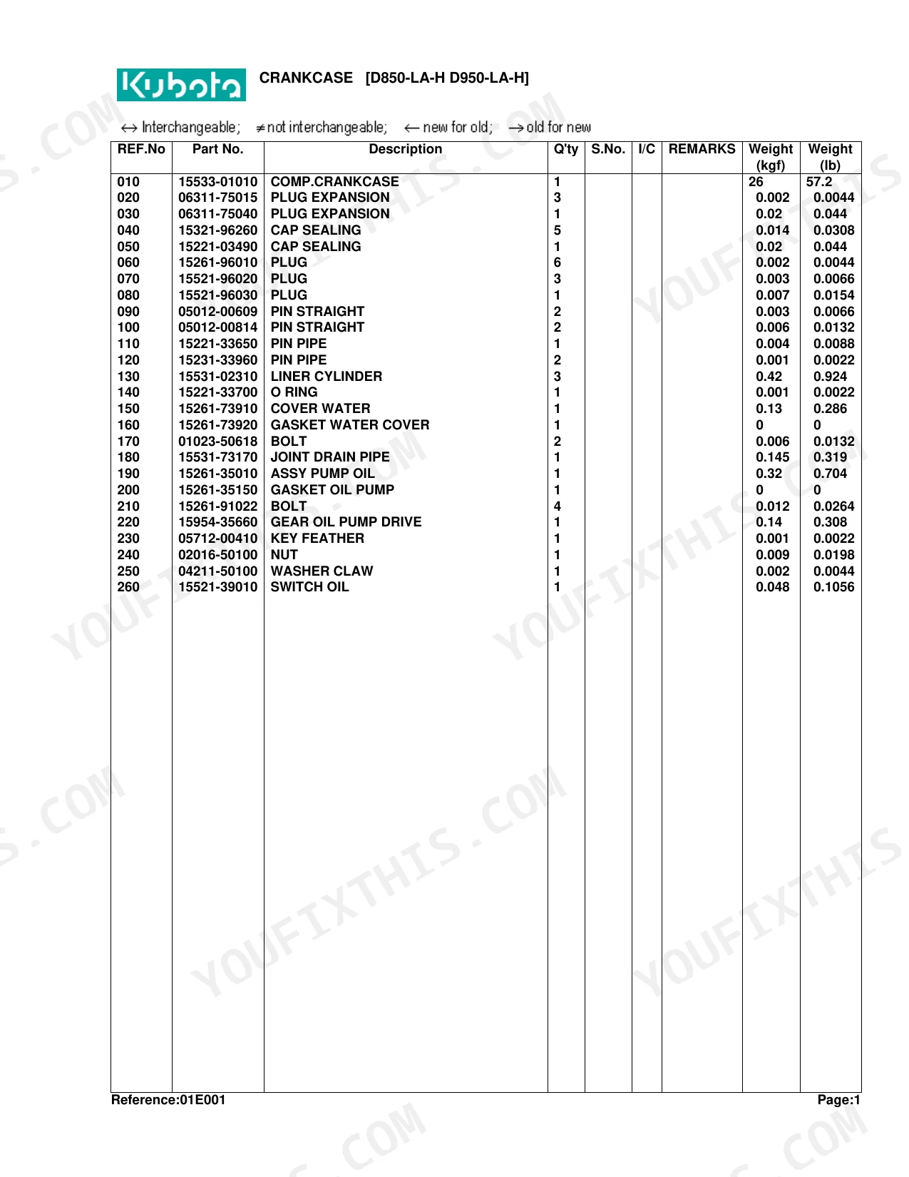
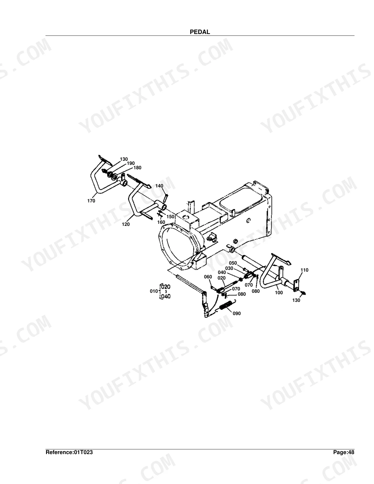
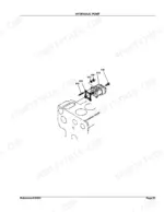
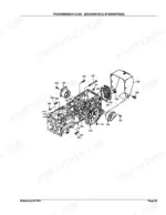
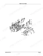
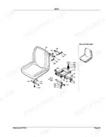
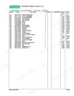
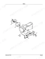
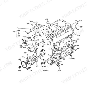
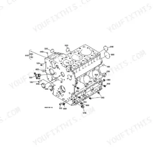
Skip the trip to the dealer counter. This Kubota B7200HSTD Parts Catalog (OEM #100K0070) hands you the right part number across 168 pages, built from 60 parts lists matched to exploded-view diagrams. Coverage runs the full machine: D850/D950 engine internals, the HST transmission, front and rear differentials, hydraulic pump and block, 3-point linkage, and the control valve. Every diagram lays out how components fit together, and each parts list carries reference numbers, part numbers, quantities, and interchangeability data for compatible machines B6200HSTE(D) and B7200HSTE(D). Hydraulic exploded diagrams for the pump, pipe routing, and hydraulic block are included. Tired of squinting at blurry microfiche scans? Search any component by keyword and jump straight to its exploded view, on whatever device sits on your bench.
What's Inside This Kubota B7200HSTD Parts Manual
| System | Pages |
|---|---|
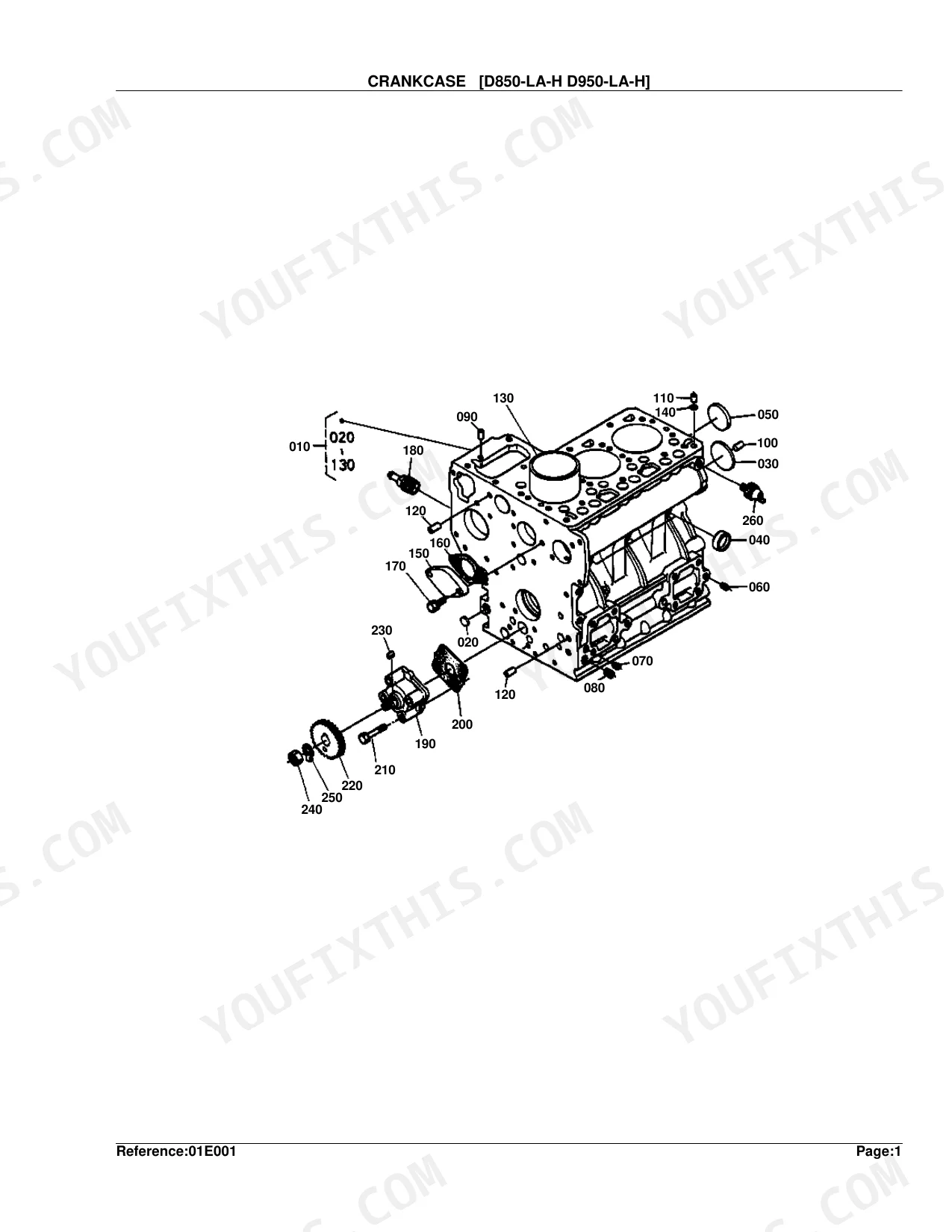
| Crankcase [D850-La-H D950-La-H] | 5-6 |
| Oil Pan | 7-8 |
| Cylinder Head | 9-10 |
| Gear Case | 11-12 |
| Main Bearing Case | 13-14 |
| Cylinder Head Cover | 15-16 |
| Manifold | 17-18 |
| Valve/Rocker Arm | 19-20 |
| Camshaft | 21-22 |
| Piston/Crankshaft | 23-24 |
| Flywheel | 25-26 |
| Injection Pump | 27-46 |
| Nozzle Holder | 29-48 |
| Engine Stop Lever | 31-32 |
| Speed Control Plate | 33-34 |
| Governor | 35-36 |
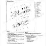
| Dynamo/Starter | 37-38 |
| Water Flange | 39-40 |
| Water Pump | 41-42 |
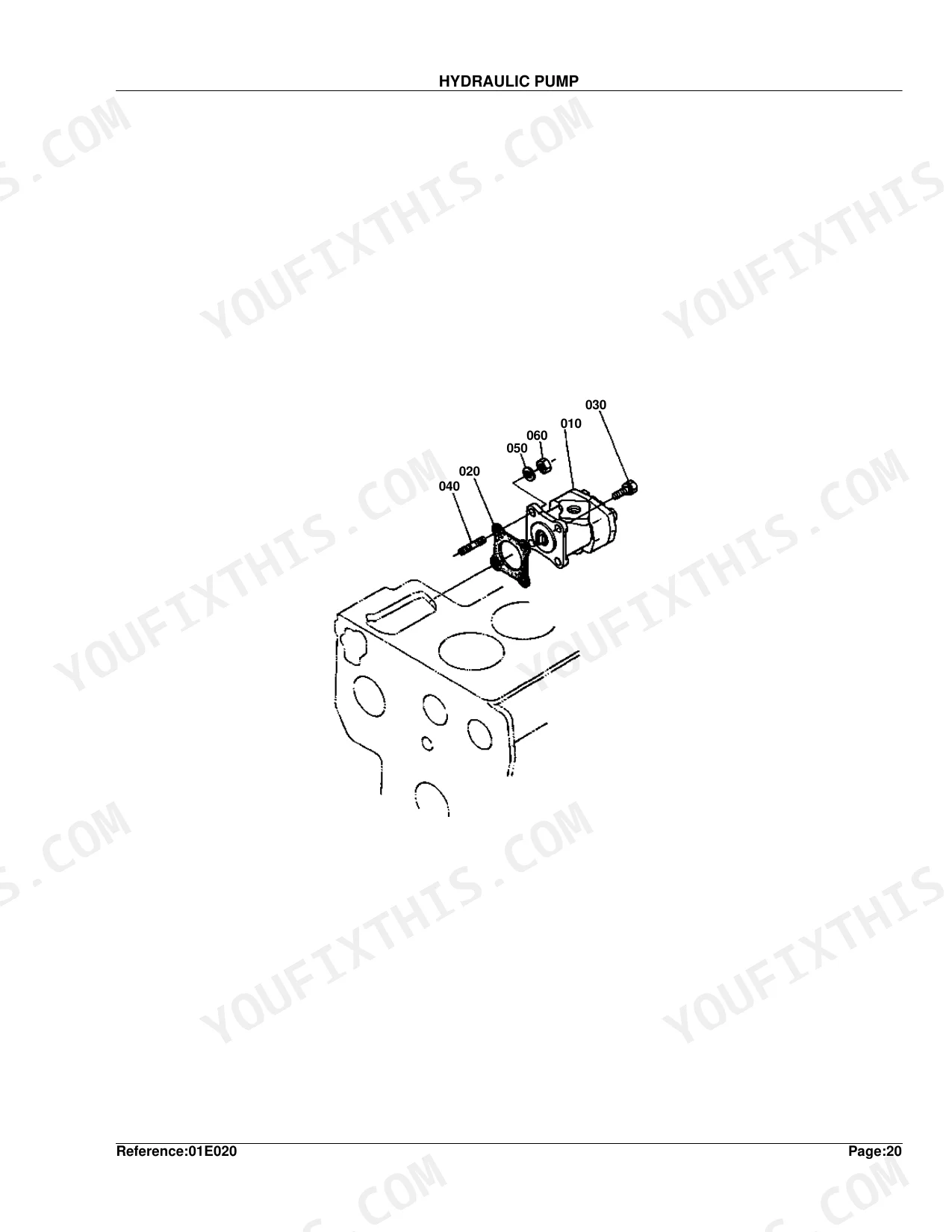
| Hydraulic Pump | 43-54 |
| Starter | 49-50 |
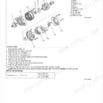
| Dynamo | 51-52 |
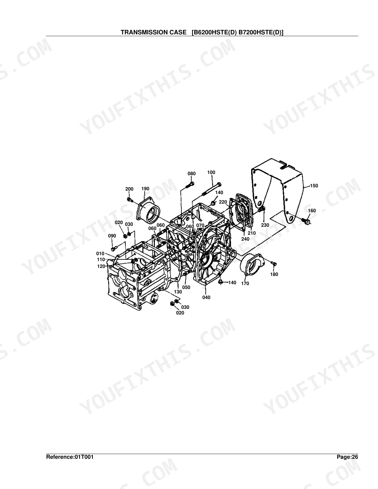
| Transmission Case [B6200Hste (D) B7200Hste (D)] | 55-56 |
| Case Cover | 57-58 |
| Rear Axle Case | 59-60 |
| Clutch Rod | 61-62 |
| Clutch | 63-64 |
| 4th Shaft | 65-66 |
| 2nd Shaft | 67-68 |
| 3rd 5th and PTO Shaft | 69-70 |
| Rear Differential | 71-72 |
| Rear Axle | 73-74 |
| Rear Wheel (9.5-16) | 75-76 |
| Rear Wheel (31 X 13.5-15) | 77-78 |
| Rear Wheel Hub | 79-80 |
| Aux.Speed Change | 81-82 |
| PTO Speed Change | 83-84 |
| Mid PTO | 85-86 |
| Brake | 87-88 |
| Hydraulic Pipe | 89-90 |
| HST | 91-92 |
| Hydraulic Block | 93-94 |
| Hydraulic 2 | 95-96 |
| Steering | 97-98 |
| Pedal | 99-100 |
| Speed Change Lever | 101-102 |
| Brake Rod | 103-104 |
| Release Rod | 105-106 |
| Speed Change 1 | 107-108 |
| Speed Change 2 | 109-110 |
| Seat | 111-112 |
| Label | 113-114 |
| Clutch Housing | 115-116 |
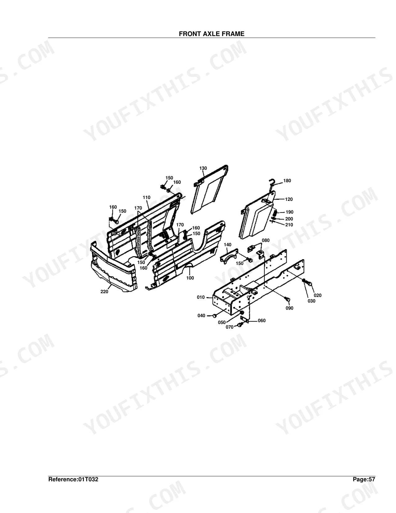
| Front Axle Frame | 117-118 |
| Radiator | 119-120 |
| Fender | 121-122 |
| Hood | 123-124 |
| Battery | 125-126 |
| Muffler | 127-128 |
| Fuel Tank | 129-130 |
| Fuel Filter | 131-164 |
| Air Cleaner | 133-134 |
| Decompress Wire/Engine Stop Wire | 135-136 |
| Panel | 137-138 |
| Panel Switch | 139-140 |
| Light | 141-142 |
| Front Axle Arm | 143-144 |
| Bevel Gear Case | 145-146 |
| Front Axle Case | 147-148 |
| Knuckle Arm | 149-150 |
| Front Differential | 151-152 |
| Bevel Gear | 153-154 |
| Drive Shaft | 155-156 |
| Front Wheel (6-12) | 157-158 |
| Front Wheel (20.5-8.00 X 10) | 159-160 |
| 3-Point Linkage | 161-162 |
| Control Valve | 165-167 |
| Accessories and Service Parts | 168-168 |
Every system also includes a diagram, interchangeability information, and a parts list.
Quick Reference Specifications
| Specification | Value | Page |
|---|---|---|
| Torque specs for wheel lug nuts | Not found | p. -1 |
| Fuel filter specifications | Not found | p. -1 |
| Air filter specifications | Not found | p. -1 |
| Hydraulic fluid specifications | Not found | p. -1 |
| Transmission fluid specifications | Not found | p. -1 |
| Battery specifications | Not found | p. -1 |
| Starter motor specifications | Not found | p. -1 |
| Ignition switch specifications | Not found | p. -1 |
| Fuses specifications | Not found | p. -1 |
| Alternator specifications | Not found | p. -1 |
| CRANKCASE [D850-LA-H D950-LA-H] weight | 26 kgf | p. 6 |
| OIL PAN weight | 1.1 kgf | p. 8 |
Kubota B7200HSTD Common Problems This Manual Covers
Kubota B7200HSTD fuel filter part number hard to confirm when engine sputters and stalls after brief run p. 131
Check the Fuel Filter exploded view on page 131. Locate each numbered callout to identify the filter element, sediment bowl, and drain plug individually. Cross-reference the Injection Pump section on page 27, where the complete pump assembly is listed at 2.1 kgf (page 28), to confirm you have all fuel delivery parts before placing your order.
Manual Section: Injection PumpCan't locate correct hydraulic pipe and seal part numbers after system was opened during extended storage p. 89
Open the Hydraulic Pipe diagram on page 89 and trace each hose, fitting, and O-ring against the parts list. Cross-reference Hydraulic Block on page 93 and Hydraulic 2 on page 95 for secondary fittings. The HST assembly (14 kgf, page 92) ties directly into these lines, so capture every interface-point part number at once to avoid a second teardown.
Manual Section: Hydraulic PipeHST assembly component parts unclear, can't determine individual pieces needed after loss of forward or reverse drive p. 91
Turn to the HST exploded view on page 91. Since the complete HST assembly weighs 14 kgf (page 92), confirm whether you need sub-assembly or full-unit part numbers before ordering. The Transmission Case diagram on page 55 shows surrounding drivetrain components, and the Clutch section on page 63 covers clutch-side parts that interface with the HST.
Manual Section: HSTStarter motor and ignition parts difficult to identify for intermittent no-start or dead electrical system p. 49
Scan the Starter exploded view on page 49 to pin down individual components, then cross-reference Dynamo on page 51 for alternator parts. Verify the battery part number on page 125; its assembly weight, 9.3 kgf (page 126), works as an ordering double-check. Panel Switch on page 139 lists the ignition switch and fuse part numbers.
Manual Section: StarterInjection pump and nozzle holder component numbers unclear when sourcing parts for fuel delivery failure p. 27
Locate the Injection Pump diagram on page 27. The pump assembly is listed at 2.1 kgf (page 28), so use that to confirm full-assembly vs. sub-part ordering. The Nozzle Holder explodes separately on page 29 at 0.26 kgf (page 30). Match callout numbers on both diagrams to their parts lists to identify plungers, delivery valves, and seals.
Manual Section: Injection PumpFrequently Asked Questions
What are the replacement specifications for fuel filter?
Part No. 15751-43010 (ASSY FILTER FUEL) is the fuel filter replacement. It weighs 0.41 kgf (0.902 lb).
What are the replacement specifications for air filter?
Part No. 67800-58400 (ASSY CLEANER AIR) is the air filter replacement, weighing 1.41 kgf (3.102 lb).
Is this Kubota B7200HSTD Parts Catalog a digital download?
Yes. It's a 168-page searchable PDF ready to download right away. Pull it up on your phone while you're under the hood, since it runs on any device. No shipping, no waiting.
Can I print specific sections of this Kubota B7200HSTD Parts Catalog?
Yes, print as many copies as you like; there are no restrictions. Plenty of mechanics print just the section they need and carry it to the shop floor.
Does this Kubota B7200HSTD manual include hydraulic schematics?
This is a parts catalog, so it shows exploded parts diagrams rather than circuit schematics. It includes detailed exploded views of the hydraulic components — pump, control valve, cylinder, and oil lines — with OEM part numbers, not wiring-style circuit diagrams.
Document Quality
This document is a scanned PDF with an OCR layer, allowing you to search and copy the full text. The text is crisp and consistently easy to read throughout. The diagrams and illustrations are clear raster images, with all labels readable, though they may show pixelation if highly magnified. Pages are clean with no scan artifacts, marks, or skewed content, and there are no notable blank or filler pages.


Reviews
There are no reviews yet.