
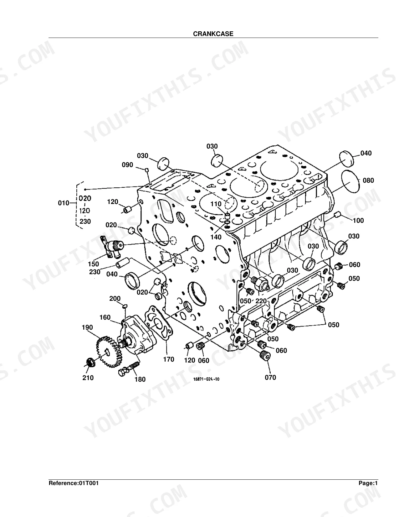
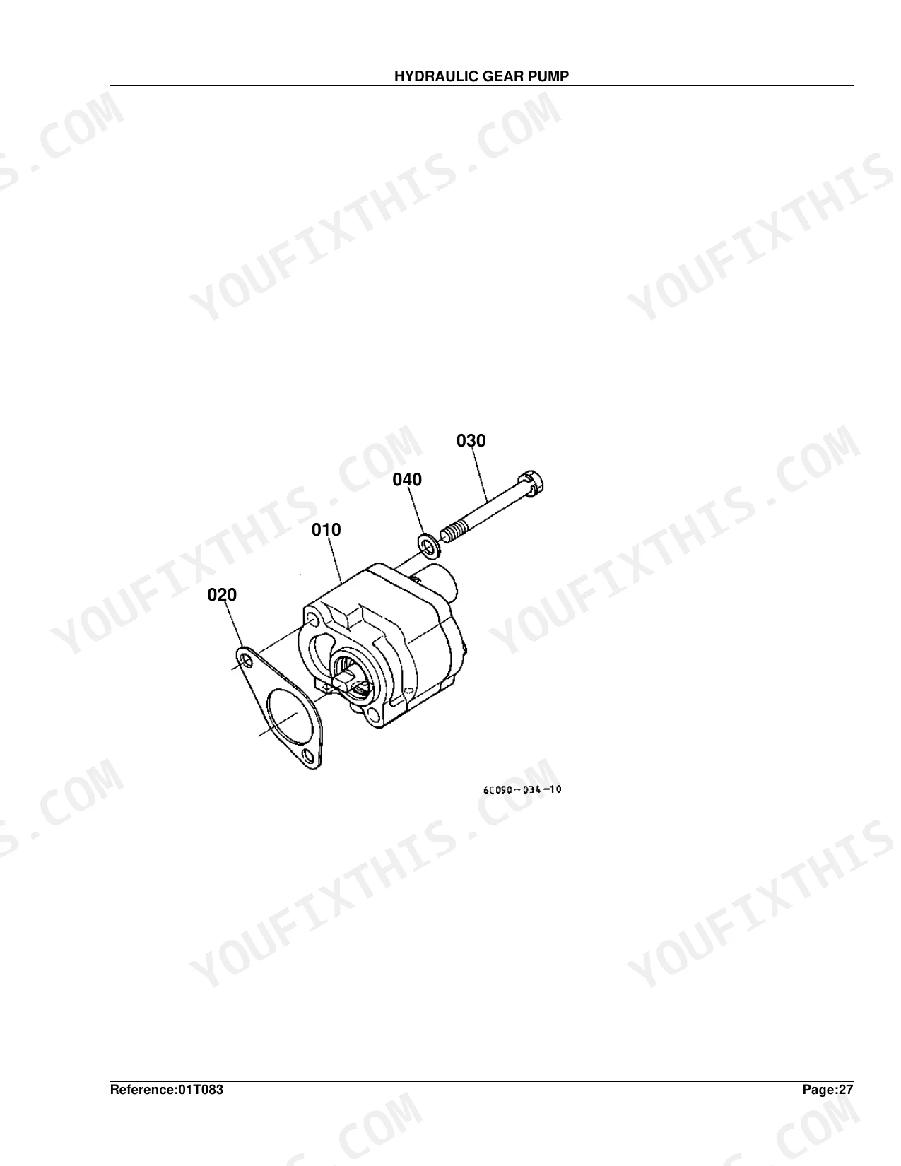
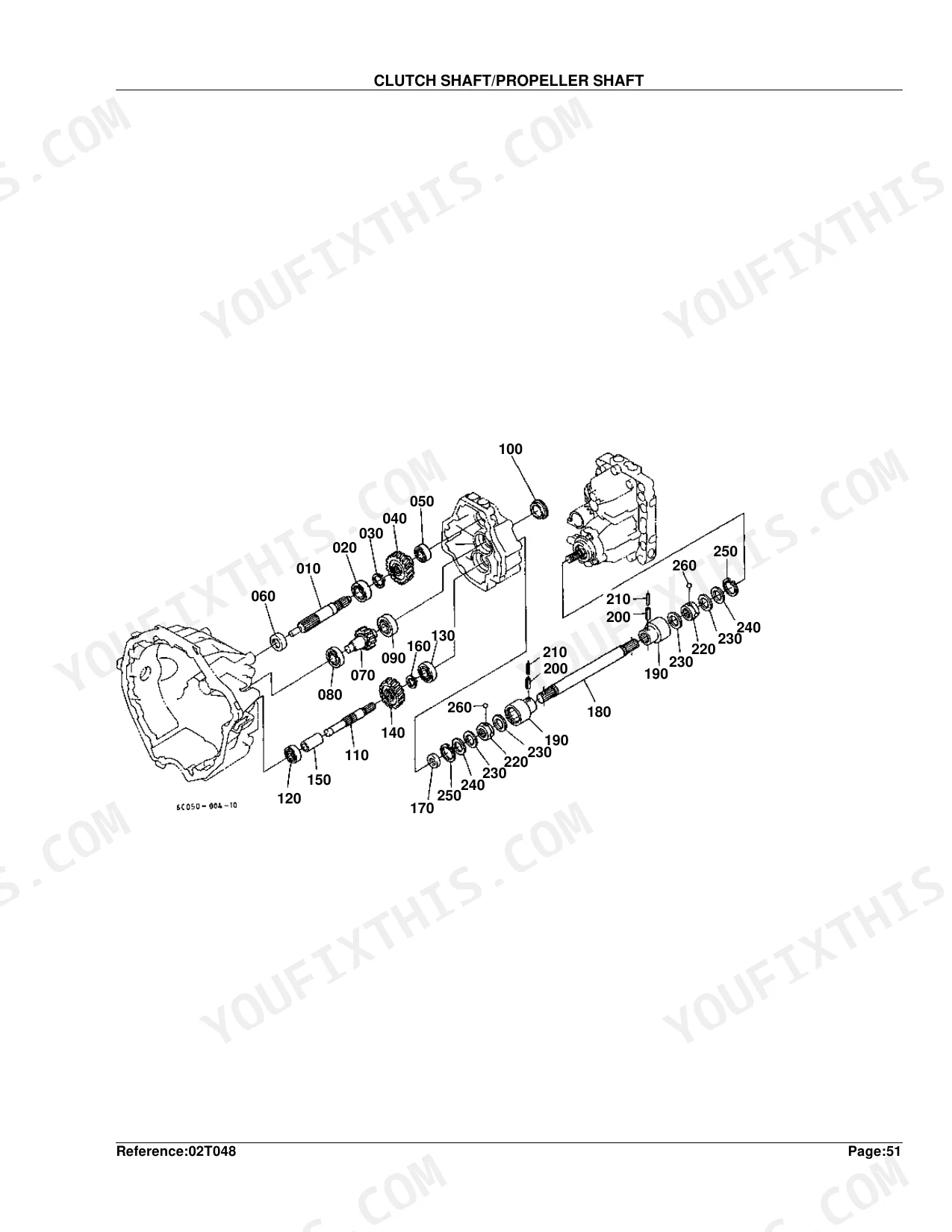
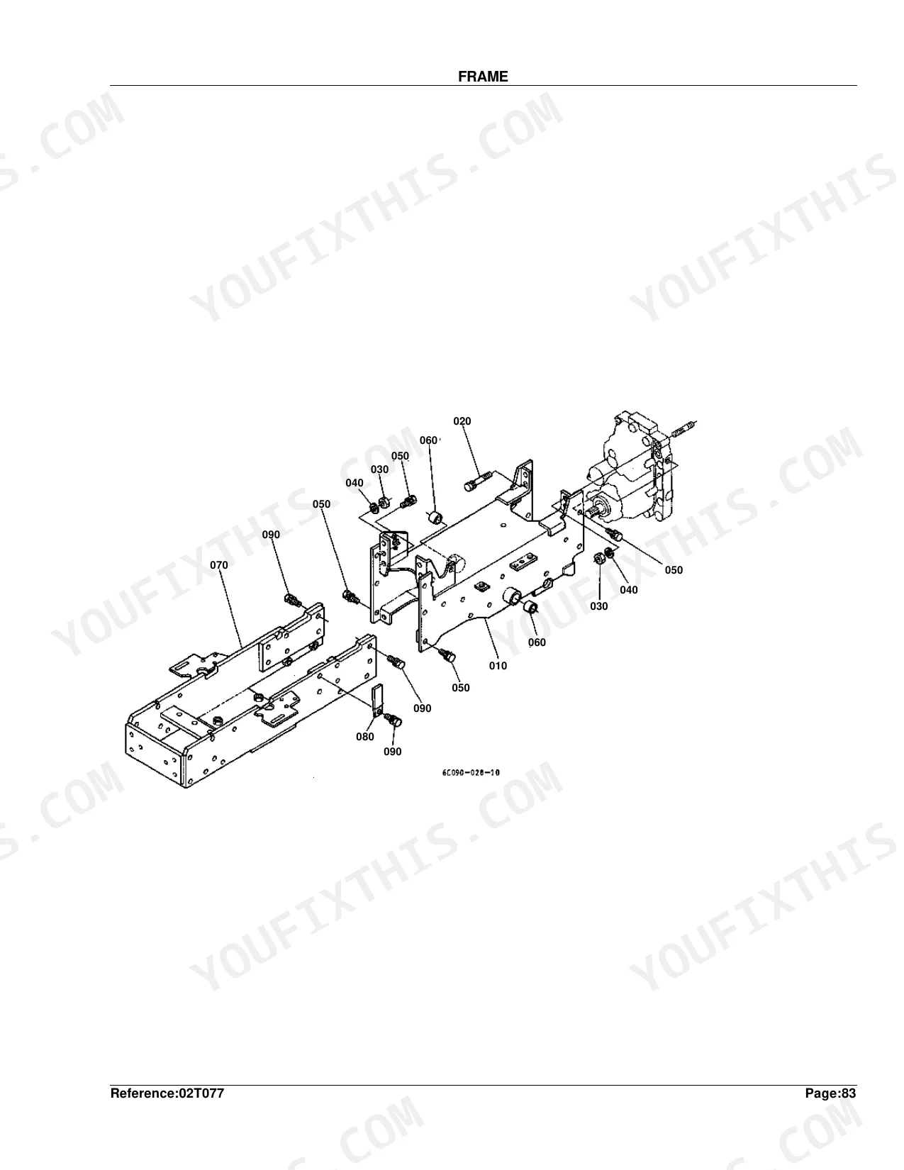
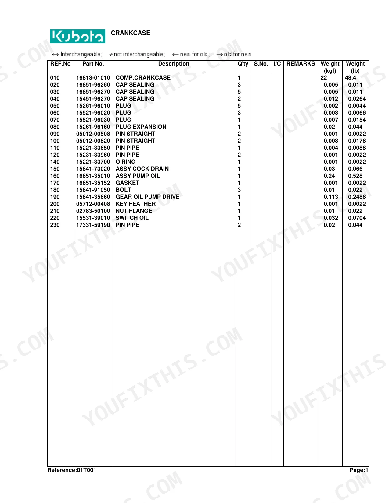
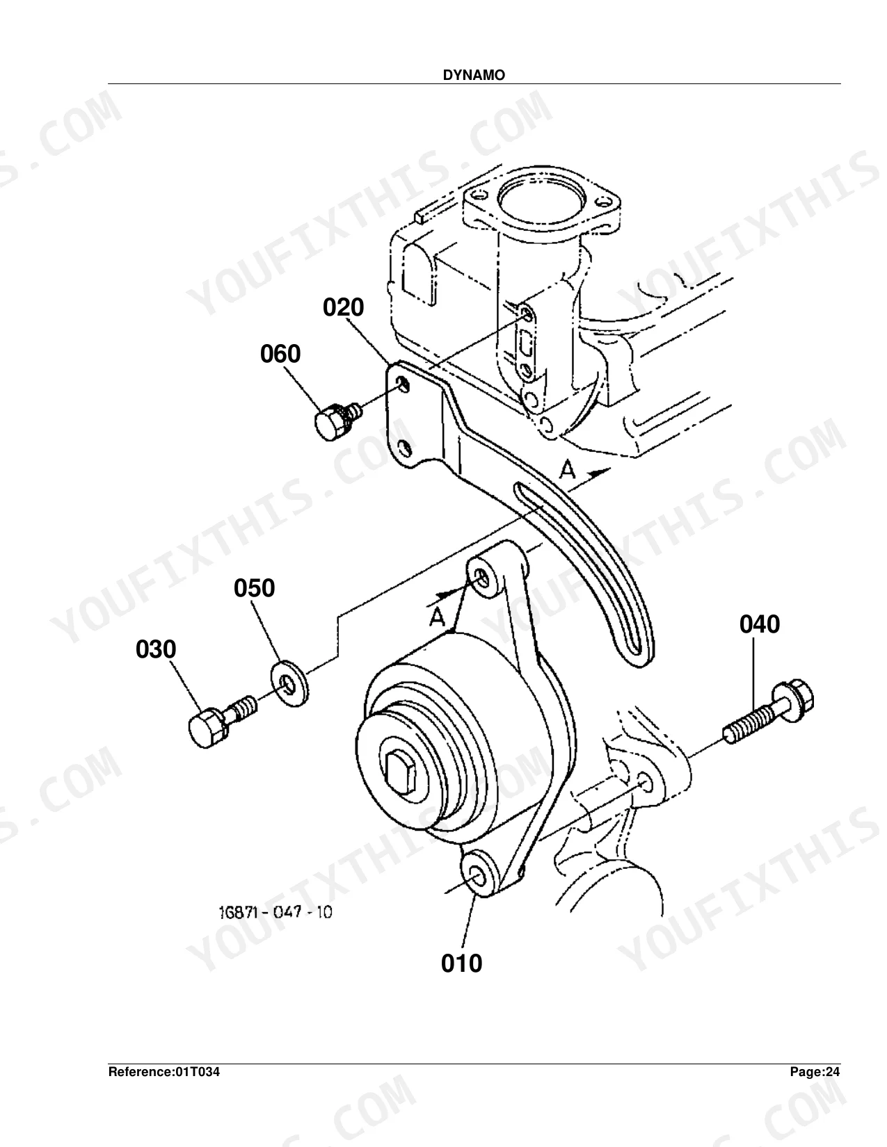
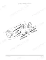
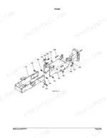
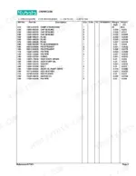
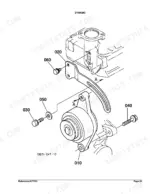
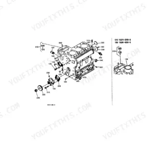
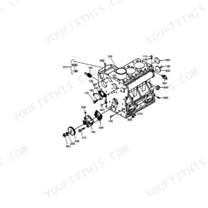
Need the factory part numbers for your Kubota B7300HSD compact tractor? This 233-page parts catalog (OEM #100K0314) maps every assembly from crankcase to ROPS in a single searchable document. It runs 55 pages of exploded parts lists with OEM numbers, plus interchangeability symbols for cross-referencing compatible components and hydraulic parts diagrams covering the gear pump, flow dividing valve, and full HST oil circuit. Component-level breakdowns go down to the injection pump, nozzle holder, dynamo, and starter, so you order the exact sub-part instead of a whole top-level assembly. Reference weights are listed throughout: the crankcase assembly at 22 kgf, the standard piston at 0.23 kgf, and nozzle holder adjusting washers spec'd to 0.900 mm. One wrong part costs you a week. Jump to any system with bookmarks and order the right piece the first time.
What's Inside This Kubota B7300HSD Parts Manual
| System | Pages | Key Topics |
|---|---|---|
| Crankcase | 5-6 | - |
| Oil Pan | 7-8 | - |
| Piston/Crankshaft | 9-10 | - |
| Main Bearing Case | 11-12 | - |
| Flywheel | 13-14 | - |
| Cylinder Head | 15-16 | - |
| Valve and Rocker Arm | 17-18 | - |
| Nozzle Holder and Glow Plug | 19-20 | - |
| Nozzle Holder [Component Parts] | 21-22 | - |
| Head Cover | 23-24 | - |
| Inlet Manifold | 25-26 | - |
| Exhaust Manifold | 27-28 | - |
| Camshaft | 29-30 | - |
| Gear Case | 31-32 | - |
| Water Pump | 33-34 | - |
| Water Flange/Thermostat | 35-36 | - |
| Injection Pump | 37-38 | - |
| Injection Pump [Component Parts] | 39-40 | - |
| Speed Control Plate | 41-42 | - |
| Governor | 43-44 | - |
| Fuel Pump | 45-46 | - |
| Lower Gasket Kit | 47-48 | - |
| Upper Gasket Kit | 49-50 | - |
| Dynamo | 51-52 | - |
| Dynamo [Component Parts] | 53-54 | - |
| Clutch | 55-56 | Rod, Pedal, Housing |
| Hydraulic Gear Pump | 57-58 | - |
| Hydraulic Gear Pump [Component Parts] | 59-60 | - |
| Air Cleaner | 61-62 | - |
| Muffler | 63-64 | - |
| Accelerator Lever | 65-66 | - |
| Fuel Tank | 67-68 | - |
| Fuel Pipe | 69-70 | - |
| Fuel Filter [Component Parts] | 71-72 | - |
| Water Pipe | 73-74 | - |
| Radiator | 75-76 | - |
| Reserve Tank | 77-78 | - |
| Fan | 79-80 | - |
| Starter | 81-82 | - |
| Starter [Component Parts] | 83-84 | - |
| Battery | 85-86 | - |
| Head Light | 87-88 | - |
| Hazard Light/Tail Light | 89-90 | - |
| Meter/Switch | 91-92 | - |
| Meter Kit | 93-94 | - |
| Meter [Component Parts] | 95-96 | - |
| Wire Harness | 97-98 | - |
| Clutch Shaft/Propeller Shaft | 105-106 | - |
| Transmission Case | 107-108 | - |
| Differential Gear Case | 109-110 | - |
| HST | 111-112 | - |
| HST [Component Parts] | 113-115 | - |
| 2Nd/3Rd/4Th Shaft | 116-117 | - |
| 5Th Shaft/PTO Shaft | 118-119 | - |
| Front Wheel Drive Shaft | 120-121 | - |
| Mid PTO | 122-123 | - |
| Speed Change Lever | 124-125 | Speed Control Pedal, Speed Set Lever, Range Gear Shift Lever, Pto Gear Shift Lever, Front Wheel Drive Lever |
| Rear Differential | 136-137 | - |
| Differential Lock Pedal | 138-139 | - |
| Rear Axle Case | 140-142 | - |
| Rear Axle | 143-144 | - |
| Rear Wheel (29 X 12.5-15) | 145-146 | - |
| Rear Wheel (8.3-16) | 147-148 | - |
| Rear Wheel (31 X 15.5-15) | 149-150 | - |
| Brake | 151-152 | Pedal, Parking Brake Lever |
| Front Drive Shaft | 157-158 | - |
| Front Differential | 159-160 | - |
| Front Axle Case | 161-162 | - |
| Front Bevel Gear Case | 163-164 | - |
| Front Axle | 165-167 | - |
| Front Wheel (6-12) | 168-169 | - |
| Front Wheel (21 X 8.00-10) | 170-171 | - |
| Frame | 172-173 | - |
| Steering Wheel | 178-180 | - |
| Steering | 181-182 | Knuckle Arm/Tie Rod, Drag Link, Wheel, [Component Parts] |
| Hydraulic Oil Line (Oil Cooler) | 185-186 | - |
| Hydraulic Oil Line (T/M) | 187-188 | - |
| Hydraulic Oil Line (Suction/Delivery) | 189-190 | - |
| Flow Dividing Valve [Component Parts] | 191-192 | - |
| Hydraulic Oil Line (HST) | 193-194 | - |
| Oil Cooler | 195-196 | - |
| Hydraulic Cylinder Case | 197-199 | - |
| Control Valve | 200-201 | - |
| Control Valve [Component Parts] | 202-203 | - |
| Hydraulic Control Lever | 204-205 | - |
| Top Link | 206-207 | - |
| Lower Link | 208-209 | - |
| Lift Rod | 210-211 | - |
| Hood (Bonnet) | 212-213 | - |
| Front Grille | 214-215 | - |
| Side Cover | 216-218 | - |
| Fender Lh | 219-220 | - |
| Fender Rh | 221-222 | - |
| Seat Stay | 223-224 | - |
| Seat | 225-226 | - |
| Step | 227-228 | - |
| ROPS | 229-230 | - |
| Label | 231-232 | - |
| Accessories and Service Parts | 233-233 | - |
Quick Reference Specifications
| Specification | Value | Page |
|---|---|---|
| CRANKCASE (COMP.CRANKCASE) Weight | 22 kgf | p. 6 |
| OIL PAN (COMP.OIL PAN) Weight | 0.75 kgf | p. 8 |
| PISTON (STD) Weight | 0.23 kgf | p. 10 |
| NOZZLE HOLDER (WASHER ADJUSTING) Thickness | 0.900MM | p. 22 |
| DYNAMO (ASSY DYNAMO) Weight | 1.33 kgf | p. 52 |
| CLUTCH (COMP.DISK CLUTCH) Weight | 0.92 kgf | p. 56 |
| FUEL TANK (ASSY TANK FUEL) Weight | 2.5 kgf | p. 68 |
| STARTER (ASSY STARTER) Weight | 3.6 kgf | p. 82 |
| BATTERY (BRACKET BATTERY) Weight | 2.45 kgf | p. 86 |
| HST (ASSY HST) Weight | 15 kgf | p. 112 |
| REAR AXLE (AXLE REAR) Weight | 4.64 kgf | p. 144 |
| HYDRAULIC CYLINDER CASE (ASSY CYLINDER HYD) Weight | 12.5 kgf | p. 199 |
Kubota B7300HSD Common Problems This Manual Covers
Kubota B7300HSD hydraulic gear pump internal components needed, can't identify correct seal and rebuild part numbers p. 57
Turn to page 57 for the Hydraulic Gear Pump exploded diagram and pages 59-60 for individual component part numbers. For suction and delivery line parts connected to the pump, check pages 189-190. The hydraulic cylinder case is a separate assembly at 12.5 kgf (pages 197-199). Confirm you need gear pump internals, not lift cylinder parts, before ordering.
Manual Section: Hydraulic Gear PumpClutch slipping or not engaging, need correct disk assembly and housing component part numbers p. 55
Check the Clutch diagram on page 55 for the full assembly layout, including clutch rod, pedal, and housing. The clutch disk assembly (COMP.DISK CLUTCH) is cataloged at 0.92 kgf on page 56; use that spec to confirm the correct line item before ordering. For clutch shaft and propeller shaft parts downstream, cross-reference the Clutch Shaft/Propeller Shaft section on page 105.
Manual Section: ClutchCan't find correct upper or lower engine gasket kit part numbers for cylinder head and crankcase seals p. 47
Locate lower gasket kit parts on pages 47-48 and upper gasket kit parts on pages 49-50; each is broken down by individual part numbers. The nozzle holder adjusting washer is listed at 0.900mm thick on page 22. Verify whether it is included in the upper kit or must be ordered as a separate line item before placing your order.
Manual Section: Lower Gasket KitHST assembly part numbers needed for internal rebuild, can't identify correct component from exploded view p. 111
Find the HST assembly overview on page 111 and the complete component parts breakdown on pages 113-115. The full HST assembly (ASSY HST) is cataloged at 15 kgf on page 112; confirm this matches your unit before ordering individual sub-components. For HST hydraulic line and fitting part numbers, cross-reference the hydraulic oil line section on pages 193-194.
Manual Section: HST3-point hitch won't lift, need control valve and lift cylinder assembly part numbers to order p. 197
Open the Hydraulic Cylinder Case exploded view on pages 197-199 for lift cylinder part numbers; the complete assembly (ASSY CYLINDER HYD) is listed at 12.5 kgf on page 199. For control valve component parts governing lift, turn to pages 202-203. Cross-reference hydraulic control lever parts on pages 204-205 for operator-side linkage and lever part numbers.
Manual Section: Hydraulic Cylinder CaseFrequently Asked Questions
What are the replacement specifications for Hydraulic gear pump?
Two part numbers cover the gear pump here. The ASSY PUMP HYDRAULIC (6C090-36300) weighs 1.2 kgf (2.64 lb). The COMP.GEAR HYD.PUMP (6C090-37202, for serial numbers >=798016) weighs 0.3 kgf (0.66 lb).
What are the replacement specifications for Clutch?
Clutch specs list two items. The COMP.DISK CLUTCH (6C090-13400) weighs 0.92 kgf (2.024 lb), and the ASSY PLATE PRESSURE (6C090-13300) weighs 2.3 kgf (5.06 lb).
What format is this Kubota B7300HSD manual in?
Immediate download of the complete 233-page searchable Parts Catalog. Read it on any device: laptop at your desk or phone out in the field.
Is this Kubota B7300HSD Parts Catalog printable?
Yes. The PDF carries no DRM restrictions, so print any page or section your shop needs. Works with any standard printer.
Can I find hydraulic circuit diagrams in this Kubota B7300HSD manual?
This is a parts catalog, so it shows exploded parts diagrams rather than circuit schematics. It includes detailed exploded views of the hydraulic components — pump, control valve, cylinder, and oil lines — with OEM part numbers, not wiring-style circuit diagrams.
Document Quality
This document is a scanned PDF with an OCR layer, allowing you to search and copy the full text. The text quality is generally crisp and easy to read throughout the parts lists and instructions, though some minor OCR artifacts are present, such as the arrow symbols appearing as '‡'. All diagrams and illustrations are clear raster images with sharp lines and readable labels, even at high zoom levels. Pages are clean with no noticeable scan artifacts, stains, or skewed content. There are no unexpected blank or filler pages.


Reviews
There are no reviews yet.