
Built around the BX25 tractor and three matched attachments, this 448-page service manual takes in the RCK54(P)-23BX and RCK60B-23BX rotary mowers, the LA240 front loader, and the BT601 backhoe. Wiring diagrams trace the starting, charging, and lighting systems; hydraulic schematics follow every circuit from the steering controller to the backhoe control valve. Engine, transaxle, front axle, and steering procedures are backed by exploded-view diagrams and tightening torques spanning all four machines. Troubleshooting charts walk faults back to root cause. When you reach the torque step, mower blade screws take 103 to 118 N·m (76 to 87 ft-lbs) and the LA240 M14 frame mounting bolts take 147 N·m (108 ft-lbs). Everything is bookmarked by system and keyword-searchable, so you can open it on a tablet at the machine and get to work.
What's Inside This Kubota BX25 & variants Manual
| System | Pages | Key Topics |
|---|---|---|
| Tractor Safety Decals | 5-8 | Safety Decals, Part No K2581-6548-1, Part No K2581-6552-1, Part No K2581-6549-1, Part No K2581-6554-1, Part No K2591-6557-2, Part No K2581-6556-1, Part No K2581-6555-1 |
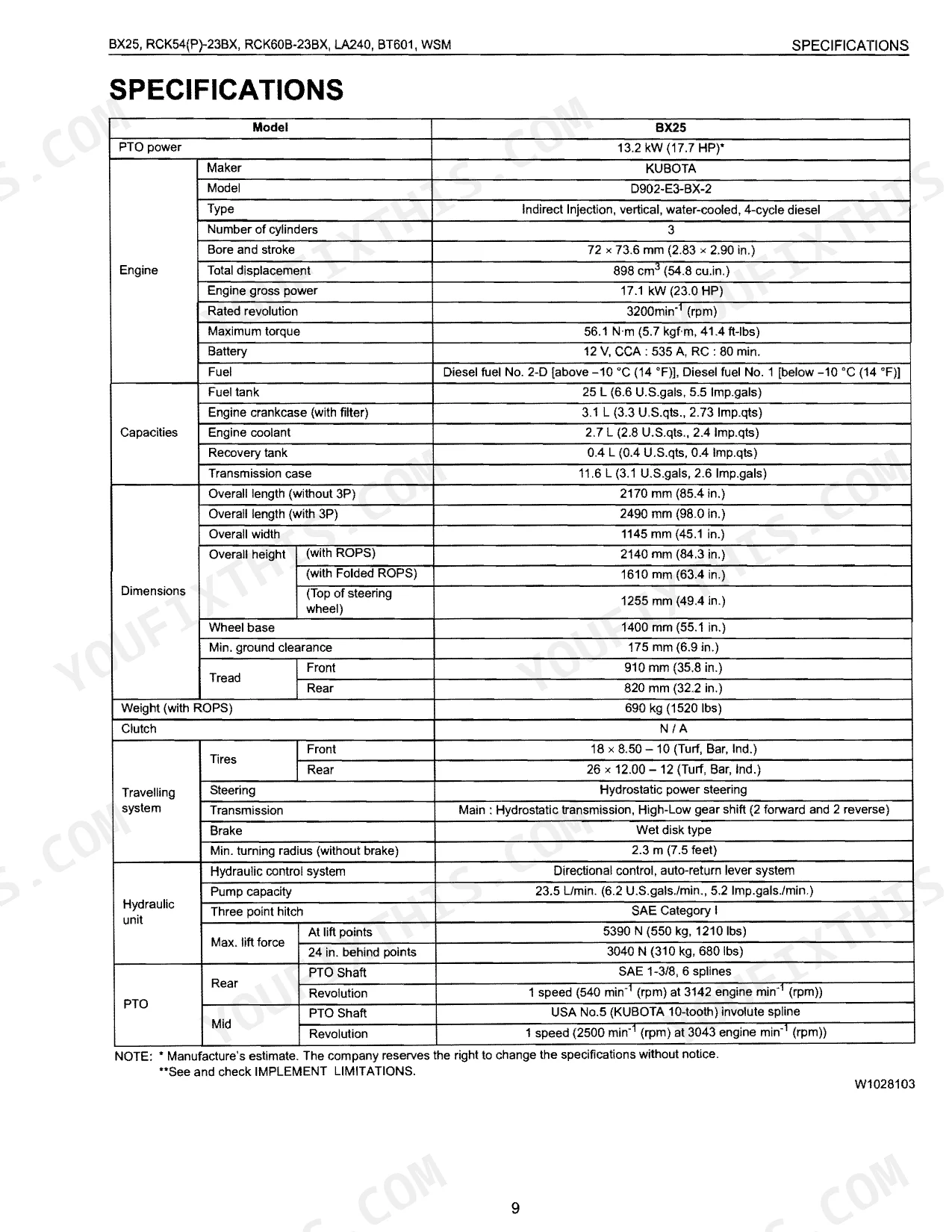
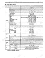
| Tractor Specifications | 9-12 | Specifications, Travelling Speeds, Dimensions |
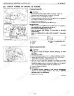
| Tractor General Information | 13-62 | Tractor Identification, Handling Precautions For Electrical Parts And Wiring (Battery, Fuse, Connector, Handling Of Circuit Tester), Lubricants Fuel And Coolant |
| Engine Mechanism | 63-68 | Lubricating System, Cooling System, Fuel System |
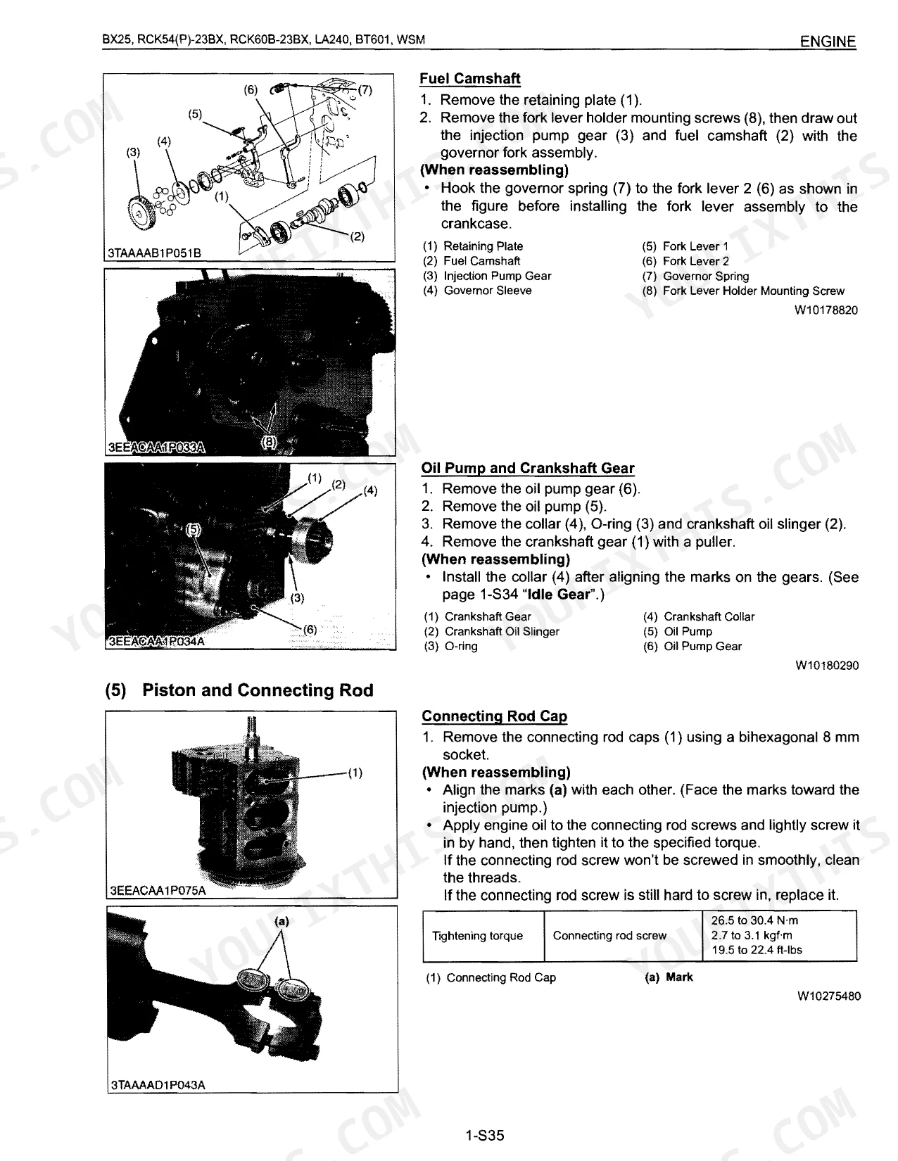
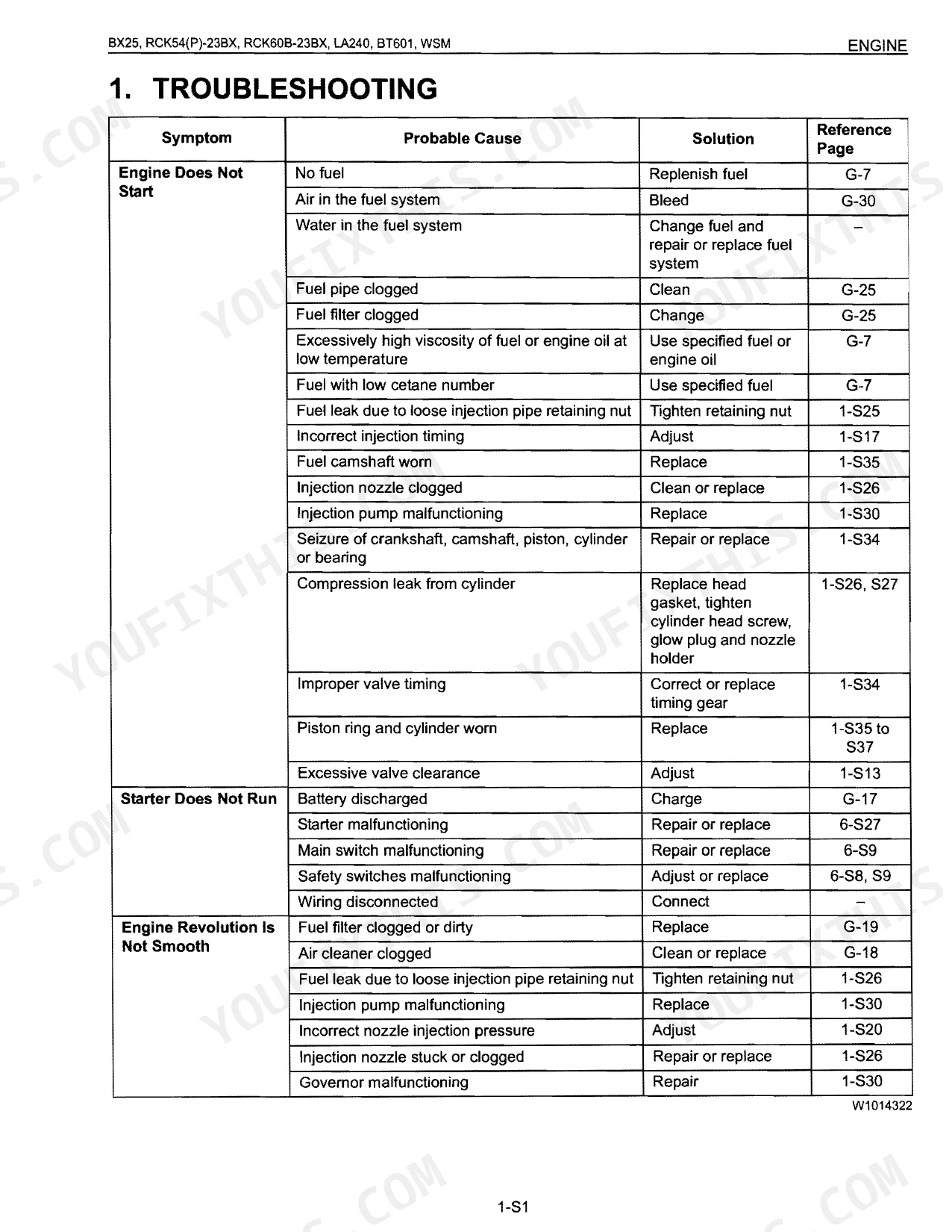
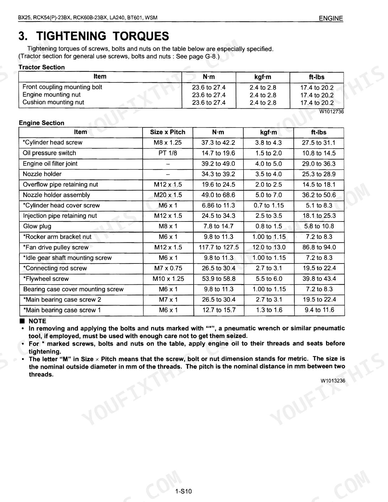
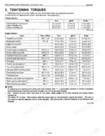
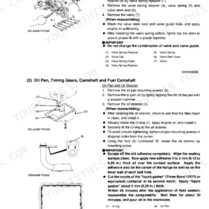
| Engine Servicing | 69-130 | Troubleshooting, Servicing Specifications, Tightening Torques, Checking, Disassembling And Servicing (Checking And Adjusting, Disassembling And Assembling) |
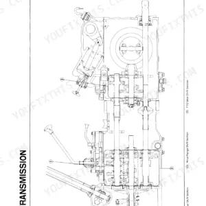
| Transaxle Mechanism | 131-152 | Structure, Travelling System (Hydrostatic Transmission, Range Gear Shift Section, Front Wheel Drive Section, Differential Gear Section, Brake Section) |
| Transaxle Servicing | 153-200 | Troubleshooting, Servicing Specifications, Tightening Torques, Checking, Disassembling And Servicing (Checking And Adjusting, Preparation, Disassembling And Assembling) |
| Front Axle Mechanism | 201-206 | Structure, Front Wheel Alignment, Camber, Kingpin Angle, Caster, Toe-in |
| Front Axle Servicing | 207-222 | Troubleshooting, Servicing Specifications, Tightening Torques, Checking, Disassembling And Servicing (Checking And Adjusting, Preparation, Disassembling And Assembling) |
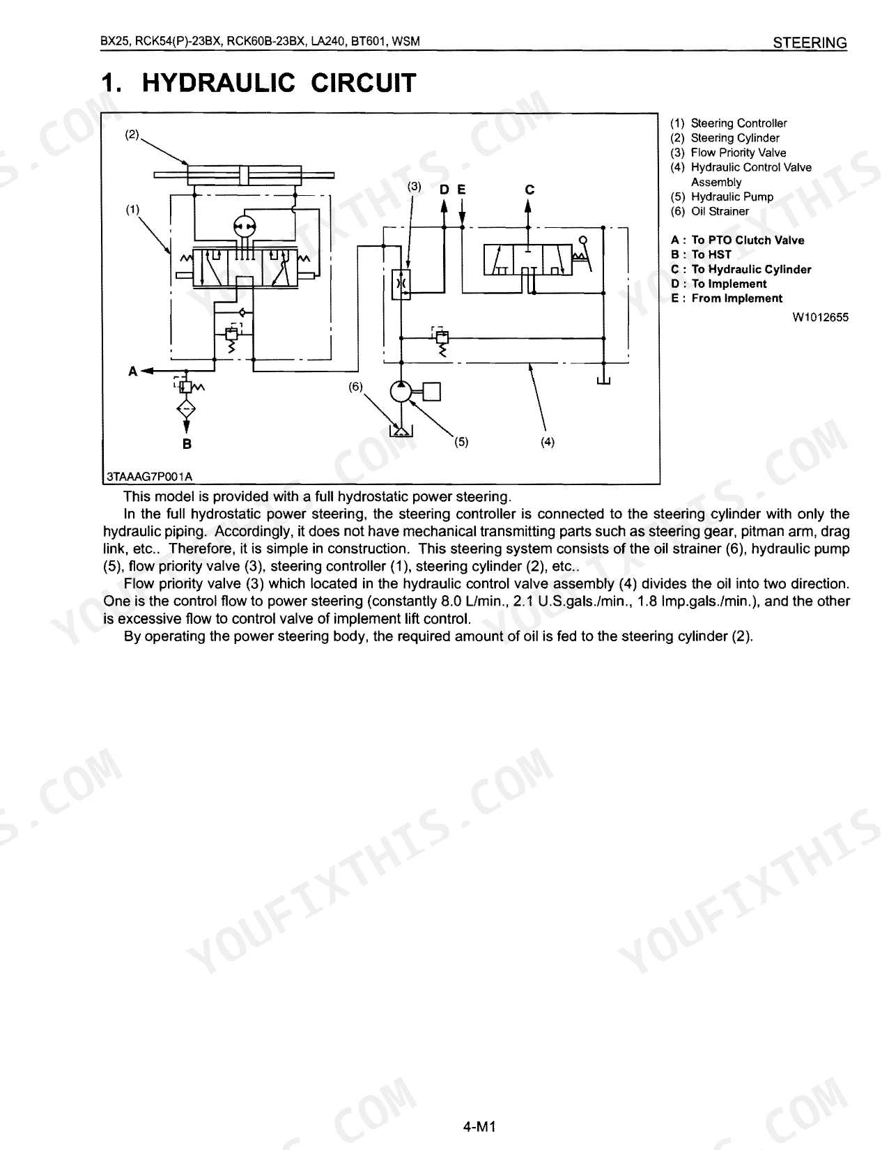
| Steering Mechanism | 223-228 | Hydraulic Circuit, Steering Controller, Steering Cylinder |
| Steering Servicing | 229-240 | Troubleshooting, Servicing Specifications, Tightening Torques, Checking, Disassembling And Servicing (Preparation, Disassembling And Assembling) |
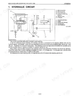
| Hydraulic System Mechanism | 241-254 | Hydraulic Circuit, Hydraulic Pump, Control Valve, Flow Priority Valve, Relief Valve, Hydraulic Cylinder, Hydraulic Block Type Outlet, Mower Linkage |
| Hydraulic System Servicing | 255-274 | Troubleshooting, Servicing Specifications, Tightening Torques, Checking, Disassembling And Servicing (Checking And Adjusting, Preparation, Disassembling And Assembling) |
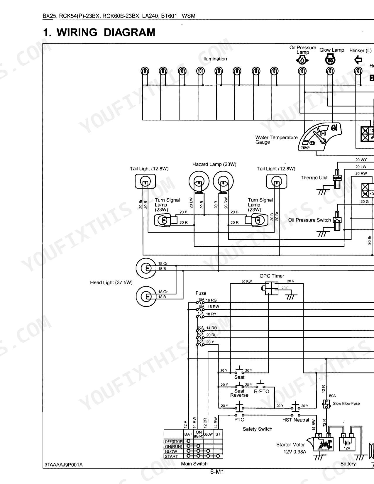
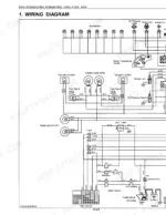
| Electrical System Mechanism | 275-290 | Wiring Diagram, Starting System (Main Switch Position, Safety Switch, Operator Presence Control), Charging System (Electrical Circuit, Ic Regulator), Lighting System |
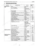
| Electrical System Servicing | 291-322 | Troubleshooting, Servicing Specifications, Tightening Torques, Checking, Disassembling And Servicing (Checking And Adjusting, Disassembling And Assembling) |
| Rotary Mower Safety Decals | 323-324 | Safety Decals, Rck60B-23Bx, Rck54-23Bx, Part No K5112-7311-1, Part No K5763-4715-1, Part No K5112-7312-1, Rck54P-23Bx, Part No K5617-7311-1 |
| Rotary Mower Terminology | 325-326 | Terminology, Rck60B-23Bx, Rck54-23Bx, Rck54P-23Bx |
| Rotary Mower Specifications | 327-328 | Specifications, Mounting Method, Cutting Height, Cutting Width, Weight Approx, Blade Spindle Speed, Blade Tip Velocity, Blade Length |
| Rotary Mower Mechanism | 329-334 | Power Transmission, Lifting Mechanism, Self-Balancer System |
| Rotary Mower Servicing | 335-364 | General (Mower Identification, Lubricants, Tightening Torques, Maintenance Check List, Check And Maintenance, Setting Up Mower, Mower Adjustment), Troubleshooting |
| Front Loader Mechanism | 365-376 | Hydraulic Circuit, Control Valve Assembly (Structure, Operation), Boom Cylinder And Bucket Cylinder |
| Front Loader Servicing | 377-396 | General (Identification, Lubricants, Maintenance Check List, Check And Maintenance), Troubleshooting, Servicing Specifications |
| Backhoe Safety Decals | 397 | Safety Decals, Part No 75597-7528-1, Part No 75595-7517-2, Part No 75595-7524-2, Part No 7K501-7529-1, Part No 75597-7517-2, Care of Danger, Warning and Caution Labels |
| Backhoe Terminology | 398 | - |
| Backhoe Specifications | 399-402 | Specifications, Operating Dimensions, Digging Force Per SAE J49, Cycle Time Seconds, Hydraulic Cylinders, Bucket Sizes, Lift Capacity Per SAE J31, Rated Lift Capacity Over End - kg |
| Backhoe Mechanism | 403-422 | Hydraulic System (Hydraulic Circuit) |
| Backhoe Servicing | 423-448 | General (Backhoe Identification, Lubricants, Maintenance Check List, Check And Maintenance), Troubleshooting, Servicing Specifications |
Quick Reference Specifications
| Specification | Value | Page |
|---|---|---|
| LA240 | ||
| Main frame mounting bolt and nut (M14) tightening torque | 147 N·m, 15.0 kgf·m, 108 ft-lbs | p. 386 |
| RCK54P-23BX | ||
| Mower blade screw tightening torque | 103 to 118 N·m, 10.5 to 12.0 kgf·m, 76 to 87 ft-lbs | p. 354 |
| BT601 | ||
| Troubleshooting: Oil leaks from joint | Repair | p. 428 |
| Hydraulic fittings (UNF) 9/16 thread size tightening torque | 37 to 44 N·m, 3.8 to 4.5 kgf·m, 27 to 33 lbf·ft | p. 433 |
| All Models | ||
| Fuel filter element replacement interval | Every 500 hours | p. 39 |
| Clearance between seat stay and seat reverse switch | 9 to 11 mm, 0.355 to 0.433 in. | p. 305 |
| Distance (L) between the foot releasing point and the machine stopping point | Approximately 3 m (10 feet) | p. 165 |
| Air cleaner element replacement interval | Once yearly or after every sixth cleaning, whichever comes first | p. 32 |
| BX25 | ||
| Engine Total Displacement | 898 cm³ (54.8 cu.in.) | p. 9 |
| Fuel Tank Capacity | 25 L (6.6 U.S.gals) | p. 9 |
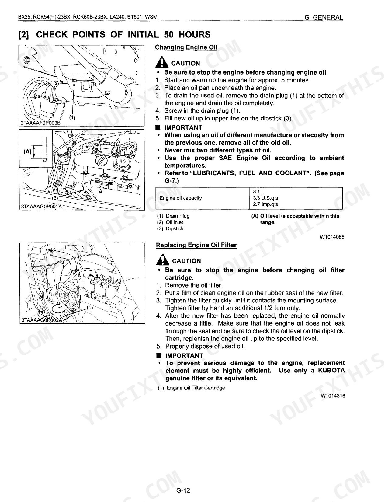
| Engine Crankcase (with filter) Capacity | 3.1 L (3.3 U.S.qts) | p. 9 |
| Engine Coolant Capacity | 2.7 L (2.8 U.S.qts) | p. 9 |
Kubota BX25 & variants Common Problems This Manual Covers
Kubota BX25 engine stalls after running an hour, won't restart, fuel tank still shows fuel
Check the fuel filter and replace it every 500 hours (page 39). Pull the tank screen and look for debris at the pickup tube. Prime the system by turning the key switch to "ON" for about 30 seconds so the pump pushes air out (page G-30). From there, follow the troubleshooting flowchart to pin the fault to the pump or the lines.
Manual Section: Engine ServicingSafety interlock trips, no-crank condition even with battery fully charged and PTO disengaged p. 305
Test the starting circuit interlocks with the wiring diagram on page 277. Measure seat-stay-to-seat-reverse-switch clearance: spec is 9 to 11 mm (0.355 to 0.433 in.) per page 305. Verify PTO and brake switches read open circuit when disengaged. Adjust any out-of-spec switch before replacing the starter or solenoid.
Manual Section: Electrical System ServicingHydraulic oil dripping from loader or backhoe fittings, boom lifts slowly or won't hold position p. 428
Inspect all hydraulic lines and fittings to pinpoint the leak before running any attachment. On BT601 backhoe fittings, torque 9/16 UNF connections to 37 to 44 N·m (27 to 33 lbf·ft) per page 433. Check transmission case fluid level and top off if low. Trace the backhoe troubleshooting chart on page 428 for weak-cylinder or leak-at-joint faults.
Manual Section: Backhoe ServicingHydrostatic drive pedal returns slowly or stays down, machine response feels sluggish or delayed p. 165
Free the hydrostatic pedal linkage of seized pivots, rust, or a stretched return spring. Clean and lube every pivot, then verify the HST neutral adjustment in the transaxle section on page 153. Stopping distance from foot release should be roughly 3 m (10 feet) per page 165; a longer stop points to a binding linkage or a tired return spring.
Manual Section: Transaxle ServicingMower blades spin slowly or not at all with PTO engaged and engine at full RPM p. 335
Confirm PTO engagement and verify PTO clutch operating pressure hits 1.0 to 1.3 MPa per page 159. Inspect the drive belt for wear or slip. On RCK54P-23BX decks, torque blade screws to 103 to 118 N·m (76 to 87 ft-lbs) per page 354. Run down the mower troubleshooting chart in the rotary mower servicing section on page 335.
Manual Section: Rotary Mower ServicingFrequently Asked Questions
How do I reset the Kubota BX25 safety switch/no-crank issue?
The manual lays out a start-system check covering the safety switches for the speed control pedal, PTO clutch lever, and operator's seat. Set the parking brake, stop the engine, and put the shift levers in neutral. With the speed control pedal depressed, for instance, the engine should not crank. When the system fails these tests, the troubleshooting guide says to "Adjust or replace" the faulty safety switches.
What are the torque specs for Kubota BX25 loader/backhoe bolts?
Torque values for the BX25 loader and backhoe bolts depend on the component and bolt size. For general screws, bolts, and nuts, see the tables on page 384. The front loader's main frame mounting bolt and nut (M14) takes 147 N·m (15.0 kgf·m, 108 ft-Ibs). On the backhoe, the boom cylinder piston mounting nut needs 150 to 180 N·m (15.3 to 18.3 kgf·m, 111 to 132 ft-Ibs).
How do I reset the Kubota BX25D hydraulic or backhoe settling problem?
When an implement settles or drops under its own weight, the manual points you to a few suspect parts: a worn or damaged hydraulic cylinder, worn or damaged piston O-rings, or a failing control valve. The fix is replacement, whether that's the hydraulic cylinder (page 5-S13) or the piston O-rings (page 5-S14). No explicit "reset" procedure exists for this one.
Why does my Kubota BX25 lose fuel or stall and how do I fix it?
The BX25 can lose fuel or stall for several reasons: no fuel, air or water in the fuel system, clogged fuel pipes or filter, or a fuel leak. Start by checking the fuel level and topping off if needed (page G-7). Air in the system calls for bleeding per the procedure on page G-30. Clogged pipes or filters get cleaned or replaced (page G-25, G-19). A leak from a loose injection pipe retaining nut means tightening that nut (page 1-S25, 1-S26).
What format is this Kubota BX25 & variants manual in?
Immediate download of the complete 448-page searchable Service Manual. Access it on any device, from the laptop at your desk to the phone in the field.
Are there any print restrictions on this Kubota BX25 & variants manual?
Absolutely. No DRM or copy protection. Print the whole manual or just the pages you need. Any home or office printer works.
Are electrical wiring diagrams included in this Kubota BX25 & variants manual?
Yes. You'll find full electrical schematics with wire routing diagrams, connector identification, and circuit descriptions.
Document Quality
This is a scanned document with an OCR layer, so you can search and copy the full text. The text quality is consistently crisp and easy to read throughout the manual. Diagrams and illustrations are raster images, meaning they may pixelate slightly when zoomed in, but all labels remain clearly readable. Pages are generally clean with no noticeable scan artifacts, stains, or skewed content. There are several blank pages interspersed, primarily acting as section dividers.


Reviews
There are no reviews yet.