
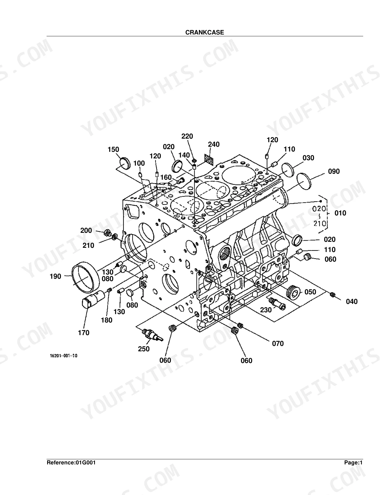
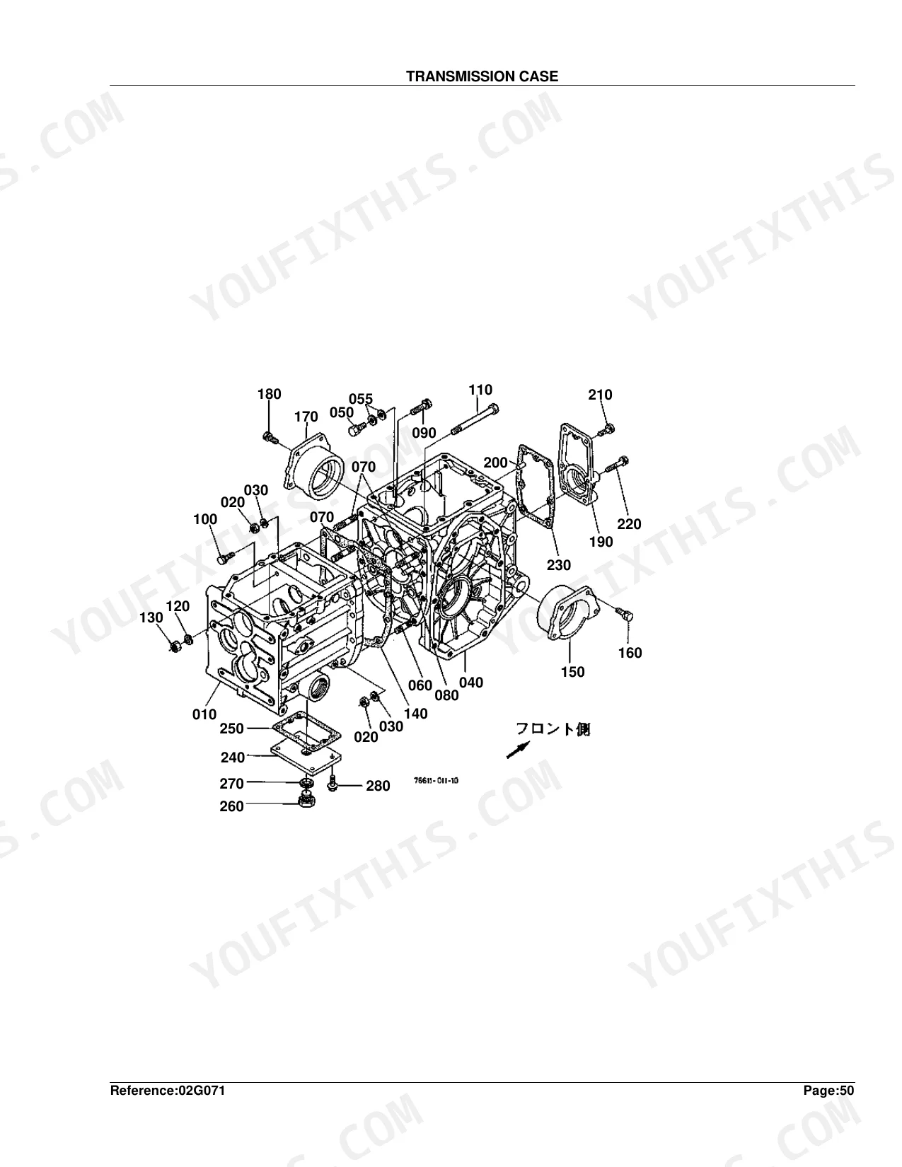
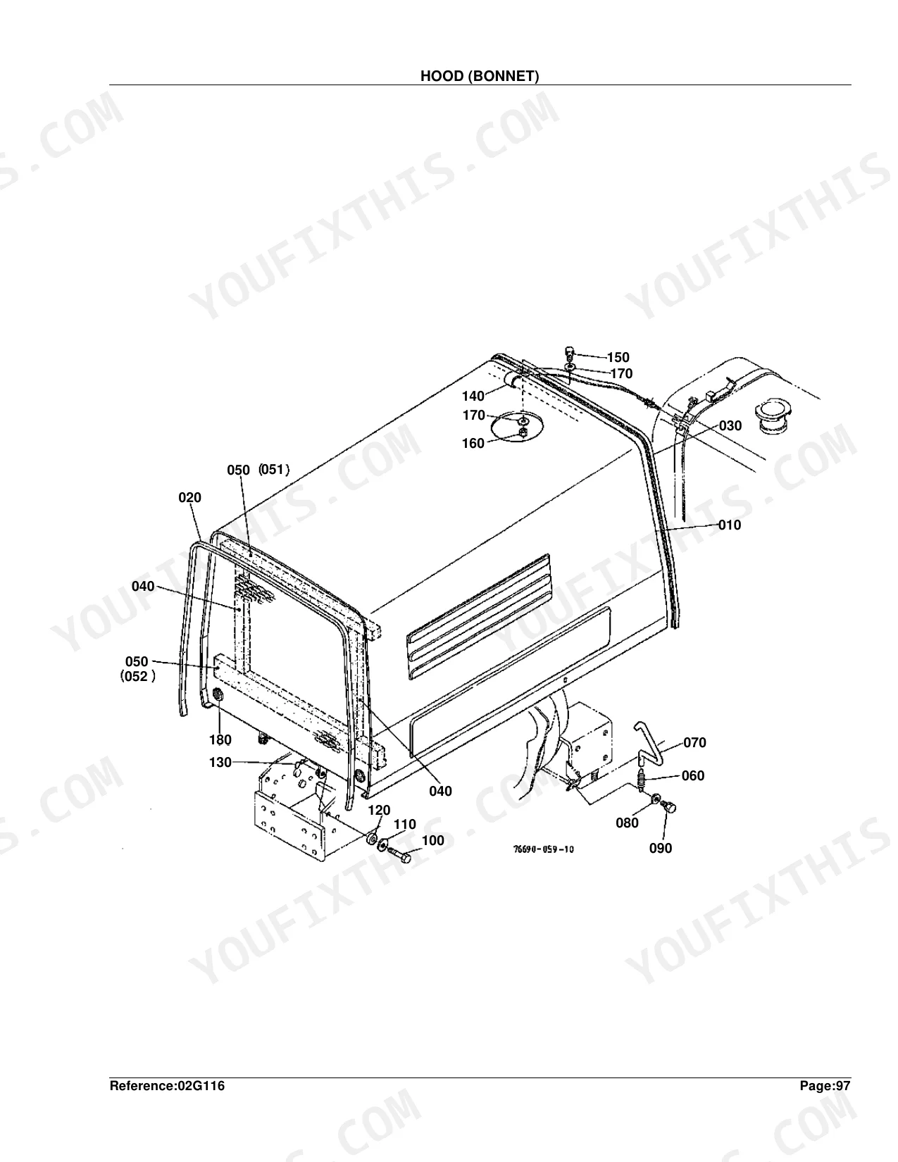
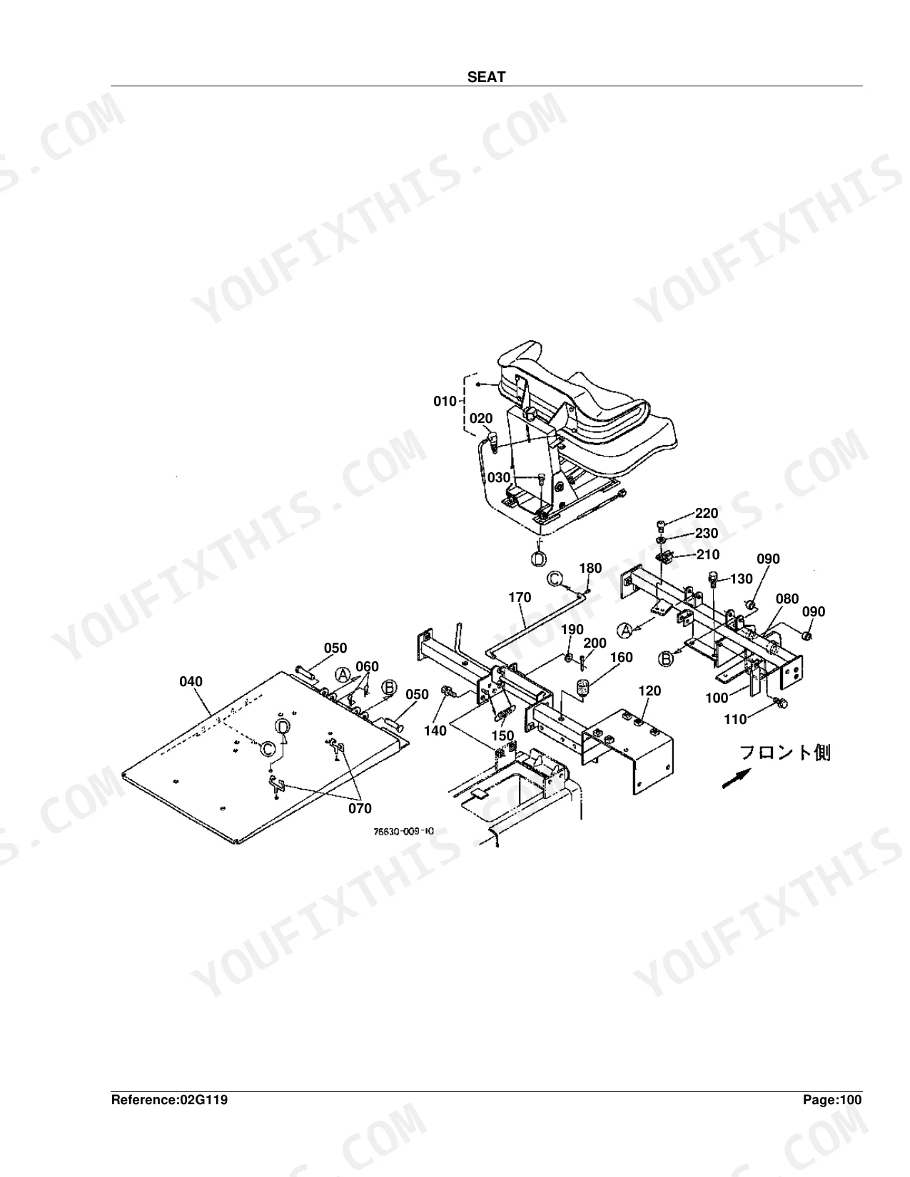
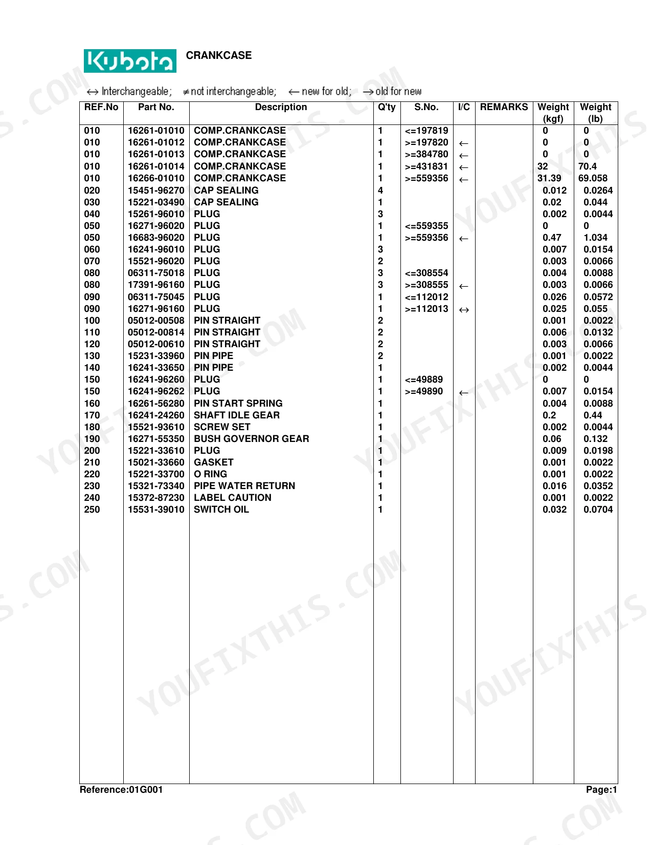
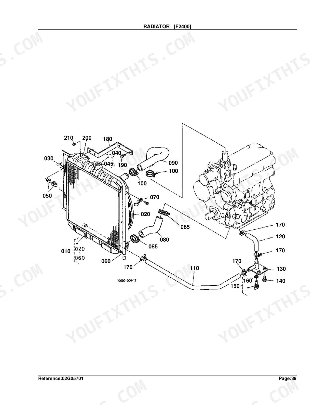
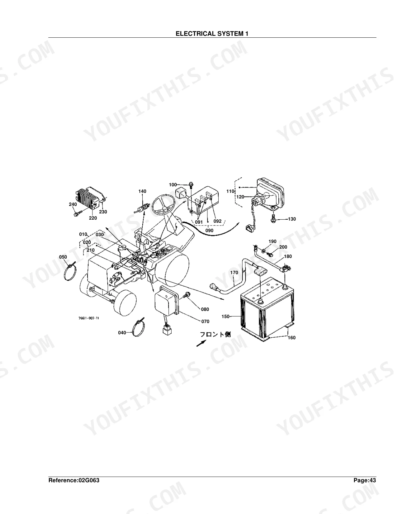
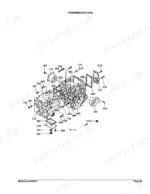
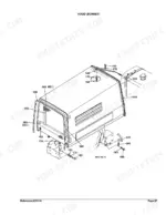
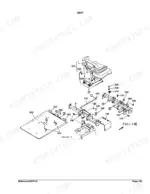
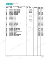
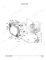
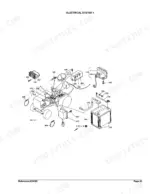
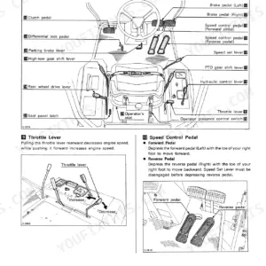
Finding the exact replacement component for your Kubota F2400 or F2100 compact tractor requires factory diagrams. This 243-page parts catalog provides the same reference material dealers use to identify hardware. It features numbered lists paired with exploded-view diagrams covering the crankcase, oil pan, and piston assemblies. The manual breaks down major systems into specific subcomponents, mapping each item to factory reference numbers alongside quantity and compatibility data. Tolerance specifications are clearly listed, allowing you to confidently order +0.5MM oversize piston rings or -0.2MM undersize crankpin bearings. Because the PDF is fully bookmarked by system, you can quickly jump to the drivetrain or electrical section and read the required part number directly from your screen.
What's Inside This Kubota F2400, F2100 Parts Manual
| System | Pages |
|---|---|
| Crankcase | 5-6 |
| Oil Pan | 7-9 |
| Piston/Crankshaft | 10-12 |
| Main Bearing Case | 13-14 |
| Flywheel | 15-16 |
| Cylinder Head | 17-18 |
| Valve/Rocker Arm | 19-20 |
| Nozzle Holder | 21-22 |
| Nozzle Holder [Component Parts] | 23-26 |
| Head Cover | 27-29 |
| Inlet Manifold | 30-32 |
| Camshaft | 33-34 |
| Gear Case | 35-36 |
| Water Pump | 37-38 |
| Water Flange | 39-41 |
| Fuel Camshaft | 42-43 |
| Injection Pump | 44-46 |
| Injection Pump [Component Parts] | 47-50 |
| Engine Stop Lever | 51-52 |
| Speed Control Plate | 53-56 |
| Governor | 57-59 |
| Upper Gasket Kit | 60-61 |
| Lower Gasket Kit | 62-63 |
| Fan | 64-65 |
| Alternator | 66-67 |
| Alternator [Component Parts] | 68-69 |
| Clutch | 70-71 |
| Hydraulic Pump | 72-73 |
| Hydraulic Pump [Component Parts] | 74-76 |
| Air Cleaner [F2400] | 77-79 |
| Muffler [F2400] | 80-82 |
| Accelerator Lever | 83-84 |
| Fuel Tank | 85-86 |
| Fuel Pipe [F2400] | 87-88 |
| Fuel Filter [F2400] [Component Parts] | 89-90 |
| Radiator [F2400] | 91-92 |
| Dustproof Plate [F2400] | 93-94 |
| Starter [F2400] | 95-96 |
| Starter [F2400] [Component Parts] | 97-98 |
| Electrical System 1 | 99-101 |
| Electrical System 2 | 102-104 |
| Light Kit [Option] | 105-107 |
| Propeller Shaft | 108-110 |
| Diff.Lock/Clutch Rod | 111-113 |
| Clutch Rod | 114-116 |
| Clutch Housing Frame | 117-118 |
| Transmission Case | 119-120 |
| Transmission Case Cover | 121-123 |
| HST [F2400] | 124-126 |
| HST [Component Parts] | 127-128 |
| Second Shaft | 129-130 |
| Third/Fifth Shaft | 131-132 |
| Fourth Shaft | 133-134 |
| Speed Change Fork and PTO Lever | 135-136 |
| Aux.Speed Change and Rear Drive Lever | 137-138 |
| Speed Change 1 | 139-141 |
| Speed Change 2 | 142-146 |
| Speed Change 3 | 147-150 |
| Differential | 151-153 |
| Axle Case | 154-155 |
| Front Axle | 156-157 |
| Front Wheel (23 X 10.5-12) | 158-159 |
| Brake | 160-162 |
| Pedal | 163-165 |
| Brake Rod | 166-168 |
| Wheel Hub | 169-170 |
| Rear Axle Case | 171-172 |
| Rear Axle Arm | 173-174 |
| Drive Shaft | 175-176 |
| Mid Case | 179-180 |
| Universal Joint | 181-186 |
| Rear Wheel (16 X 6.50-8) | 187-188 |
| Rear Axle Frame [F2400] | 189-190 |
| Knuckle Arm | 191-192 |
| Steering | 193-194 |
| Handre Post | 195-196 |
| Power Steering | 197-198 |
| Power Steering [Component Parts] | 199-200 |
| Power Cylinder [Component Parts] | 201-202 |
| Hydraulic Pipe [F2400] | 203-205 |
| Oil Cooler [F2400] | 206-208 |
| Control Valve | 209-210 |
| Control Valve [Component Parts] | 211-212 |
| Lift Cylinder [Component Parts] | 213-214 |
| Control Valve Kit [Option] | 215-217 |
| Control Valve 2 [Component Parts] | 218-219 |
| Link | 220-221 |
| Link Arm | 222-223 |
| Hood (Bonnet) | 224-225 |
| Fender | 226-228 |
| Front Frame | 229-231 |
| Seat | 232-234 |
| Seat [Component Parts] | 235-238 |
| ROPS [A][Ca] | 239-240 |
| Label | 241-242 |
| Accessoriesand Service Parts | 243 |
Every system also includes a parts list, table title, and figure caption.
Quick Reference Specifications
| Specification | Value | Page |
|---|---|---|
| Piston Ring Oversize | +0.5MM | p. 12 |
| Metal Crankpin Undersize | -0.2MM | p. 12 |
| Metal Crankshaft Undersize | -0.2MM | p. 12 |
| Metal Side Oversize | +0.2MM | p. 12 |
| Nozzle Holder Washer Adjusting Thickness (Min) | 0.900MM | p. 24 |
| Nozzle Holder Washer Adjusting Thickness (Max) | 1.950MM | p. 24 |
| Fuse Rating (Electrical System 1) | 10A | p. 101 |
| Speed Change 2 Shim Thickness (Max) | 1.8MM | p. 143 |
| Differential Shim Thickness (Max) | 1.2MM | p. 153 |
| Differential Side Shim Thickness (Max) | 0.5MM | p. 153 |
| Differential Gear Shaft Shim Thickness (Max) | 0.5MM | p. 153 |
Kubota F2400, F2100 Common Problems This Manual Covers
Need to identify Kubota F2400 speed change subassembly part numbers after the transmission starts slipping p. 142
Inspect the transmission case and speed change exploded views starting on page 119. Locate your specific gears and shafts. When ordering replacement shims for Speed Change 2 on page 142, note the maximum shim thickness is 1.8MM for correct assembly clearance.
Manual Section: Transmission System Repair PartsFinding correct differential shim and gear replacement part numbers to fix excessive axle play p. 151
Examine the differential parts breakdown on page 151 to identify the required gears and bearings. Select the appropriate replacement shims from the list, ensuring you account for the maximum differential shim thickness of 1.2MM.
Manual Section: DifferentialLocating exact electrical harness and fuse part numbers when the main dash loses power p. 99
Consult the electrical parts diagram on page 99 to pinpoint damaged wiring harness sections. Find the correct replacement fuses in the catalog list, verifying you select the exact 10A fuse rating required for Electrical System 1.
Manual Section: Electrical System 1Sourcing correct piston and ring part numbers after discovering low engine compression p. 10
Check the piston and crankshaft parts list on page 10 to find specific part numbers for rebuild components. If ordering oversized hardware, ensure you select the +0.5MM piston ring oversize parts specifically listed for this engine block.
Manual Section: Piston/CrankshaftFrequently Asked Questions
What are the replacement specifications for Drive shaft / propeller shaft?
This catalog details multiple propeller shaft components. It lists the ASSY SHAFT PROPELLER (Part No. 76630-14102 for S.No. >=11239, weighing 1.4 kgf or 3.08 lb) and the ASSY JOINT BALL (Part No. 76611-14520 for S.No. >=11239, weighing 0.22 kgf or 0.484 lb). Hardware such as the PIN SPRING (Part No. 05411-00628) is also specified.
What are the replacement specifications for Clutch and coupling components?
The replacement specifications for clutch components include "COMP.DISK CLUTCH" (Part No. 76630-13310 for S.No. >=542029, weighing 1.5 kgf or 3.3 lb) and "COMP PLATE PRESSURE" (Part No. 67111-13320, weighing 3.75 kgf or 8.25 lb). Bolts (Part No. 01123-60816) weighing 0.01 kgf (0.022 lb) are also listed.
Document Quality
This document is a scanned PDF with an OCR text layer, allowing you to search and copy the full text. The text quality is generally crisp and readable throughout the parts lists and instructions. Diagrams and illustrations are raster images, which may appear slightly pixelated when zoomed, but all labels and reference numbers within them are clear and legible. The pages are clean, free of stains, marks, or skewed content, providing a straightforward viewing experience.


Reviews
There are no reviews yet.