


Five tractors, one factory reference: the 394-page Kubota L2650–L3650 Series Service Manual (OEM #WSM 11110) documents the L2650WET, L2950WET, L3450WET, L3650WET, and L3650GST down to the last fastener. Hydraulic schematics trace oil flow through the position control, draft control, and relief valves; wiring diagrams map the starting system, charging circuit, Easy Checker gauges, and every color-coded conductor. Exploded views cover the wet clutch, transmission case, differential, and rear axle, with section-by-section troubleshooting charts throughout. Torque the cylinder head bolts to 83.4 to 88.3 N·m and the rear wheel hardware to 197 to 226 N·m. When your tractor’s down and the dealer quotes a week, pull this up on your tablet and start wrenching. Bookmarks drop you straight to the section you need.
What's Inside This Kubota L2650–L3650 Series Manual
| System | Pages | Key Topics |
|---|---|---|
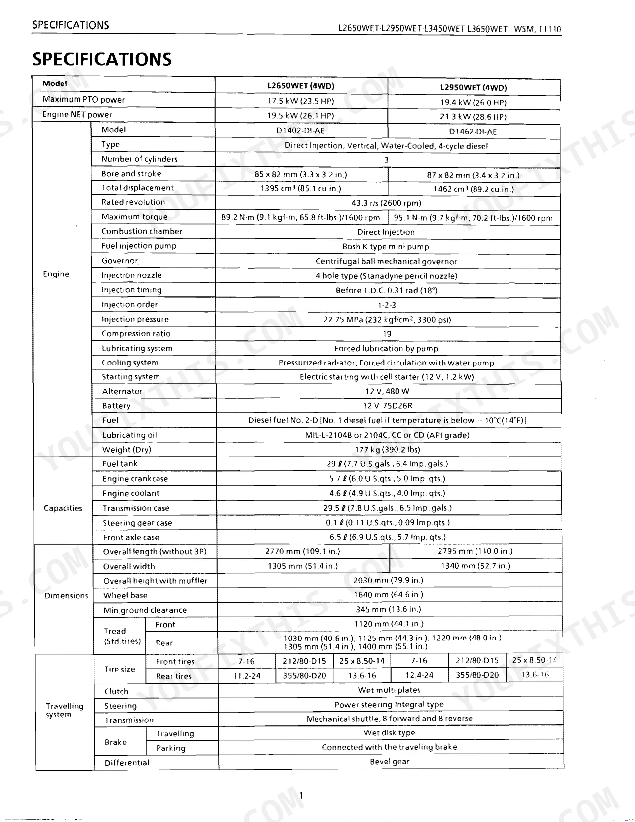
| Intro | - | Specifications, Specifications L3450WET L3650WET, Hydraulic System and PTO Specifications, Overall Dimensions |
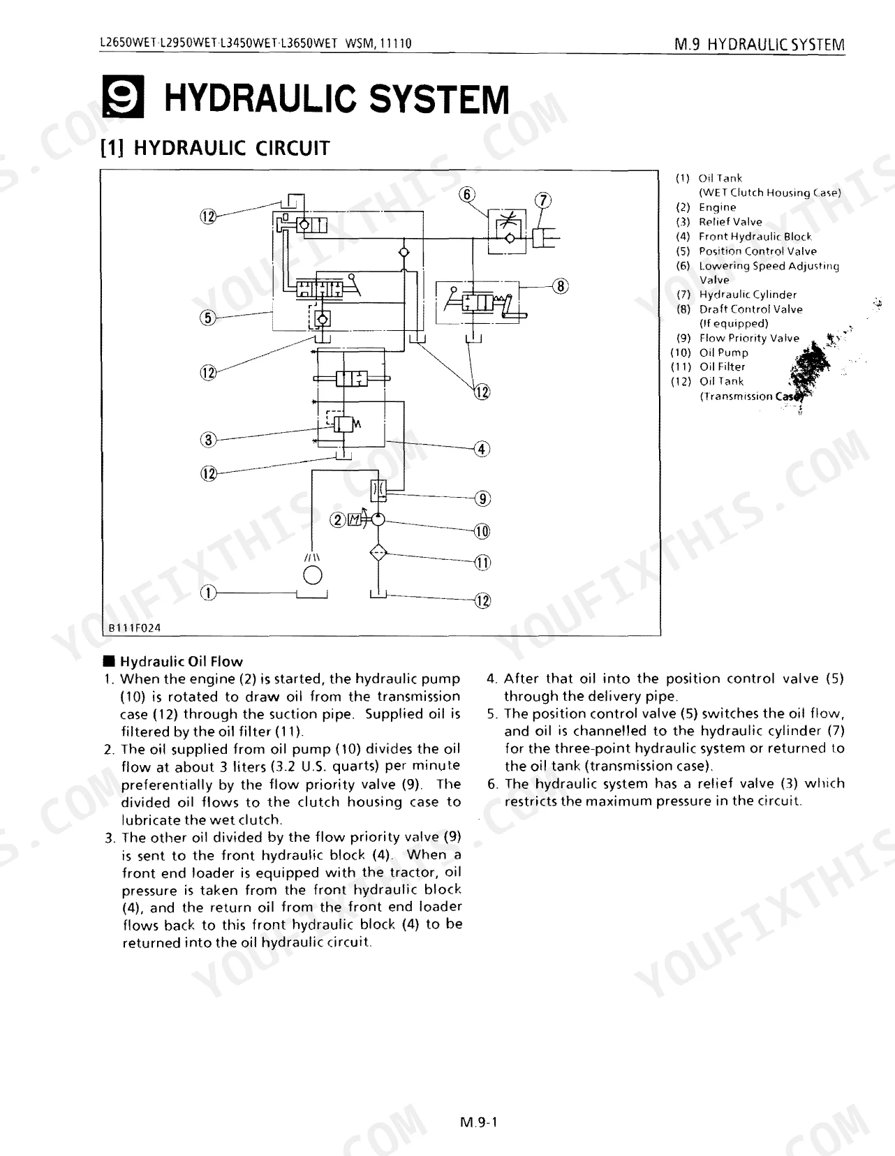
| Mechanism | - | Transmission, Shifting Mechanism, Hydraulic System and Circuit Diagraming, Hydraulic Circuit Diagram and Oil Flow |
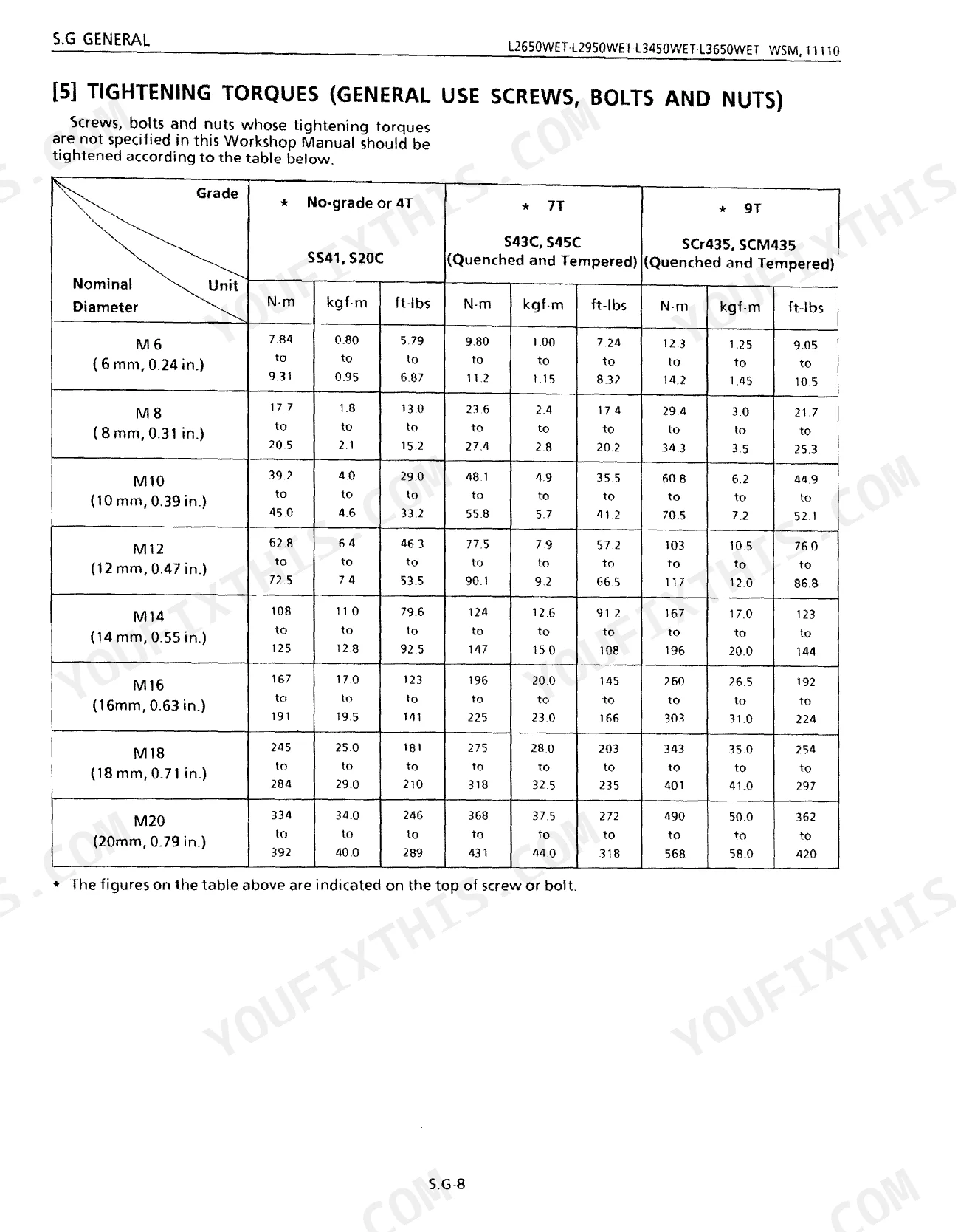
| General | - | Tractor Identification, General Precautions, Lubricants, Tightening Torques (General Use Screws, Bolts and Nuts), Maintenance Check List, Check and Maintenance |
| Seperation | - | Removing Steering Gear Box, Separating Front Axle, Separating Engine From Clutch Housing, Separating Engine, Separating Clutch Housing and Mid Case |
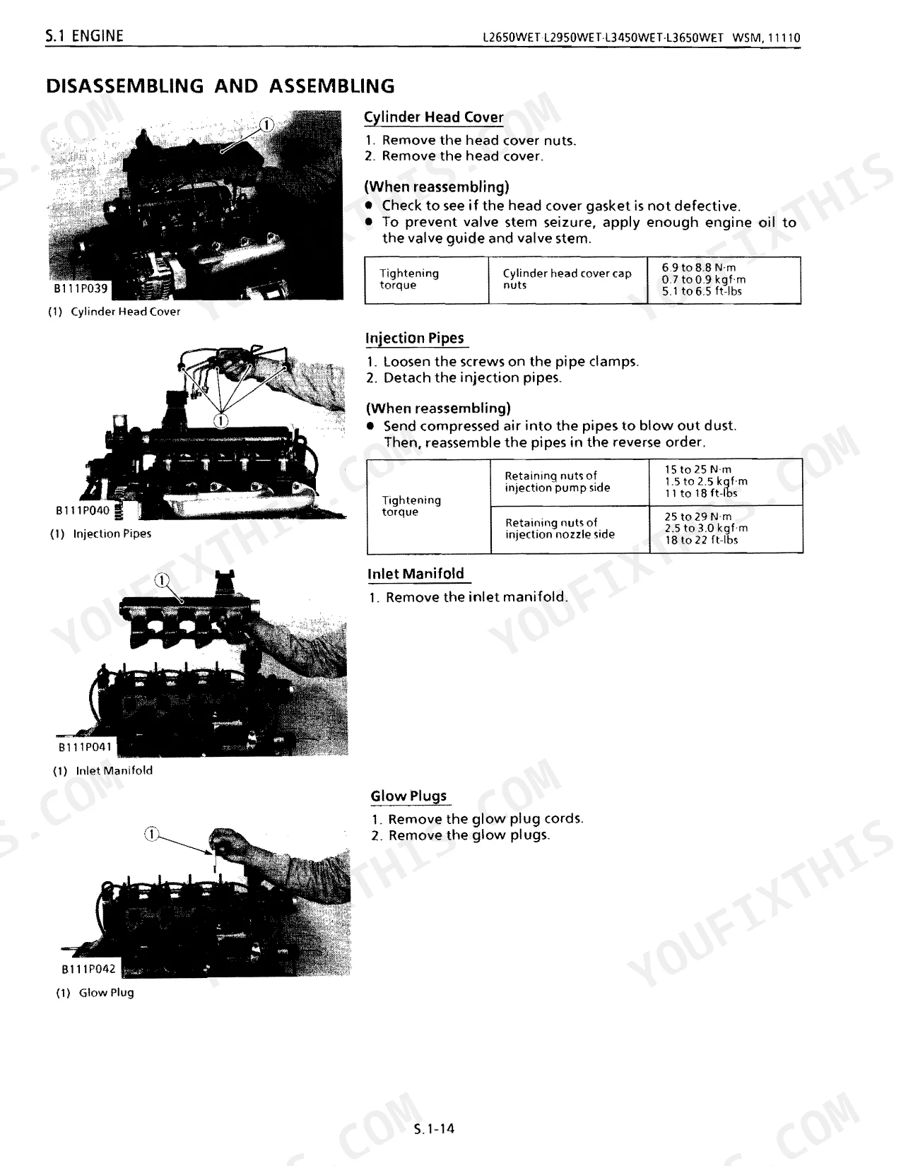
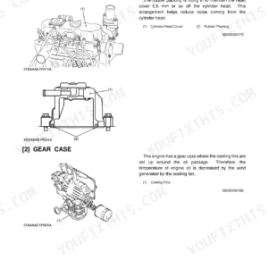
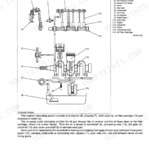
| Sect 1 Engine | - | Disassembling and Assembling (Cylinder Head, Timing Gears, Crankcase, Injection Nozzle, Injection Pump, Radiator, Water Pump, Thermostat, Oil Filter, Oil Pump) |
| Sect 2 Clutch | - | Basic Inspection, Wet Clutch |
| Sect 3 Transmission | - | Disassembling and Servicing (Clutch Housing, Mid Case, Transmission Case), Troubleshooting, Servicing Specifications, Checking |
| Sect 4 Rear Axle | - | Basic Inspection, Rear Axle, Differential Gear |
| Sect 5 Brakes | - | Basic Inspection, Brake Pedal, Brake Case |
| Sect 6 Front Axle | - | Basic Inspection, Structure, Front Wheel Alignment |
| Sect 7 Steering | - | Disassembling and Assembling (Steering Controller), Disassembling and Servicing (Steering Post and Steering Gear, Power Steering), Troubleshooting (Basic Inspection) |
| Sect 8 Hydraulic | - | Disassembling and Servicing (Hydraulic Pump, Oil Filter, Position Control Valve, Draft Control Valve, Relief Valve, Hydraulic Cylinder), Troubleshooting (Basic Inspection) |
| Sect 8 Supplement Hydrostatic Steering | - | Steering (Hydraulic Circuit, Controller, Oil Flow, Cylinder) |
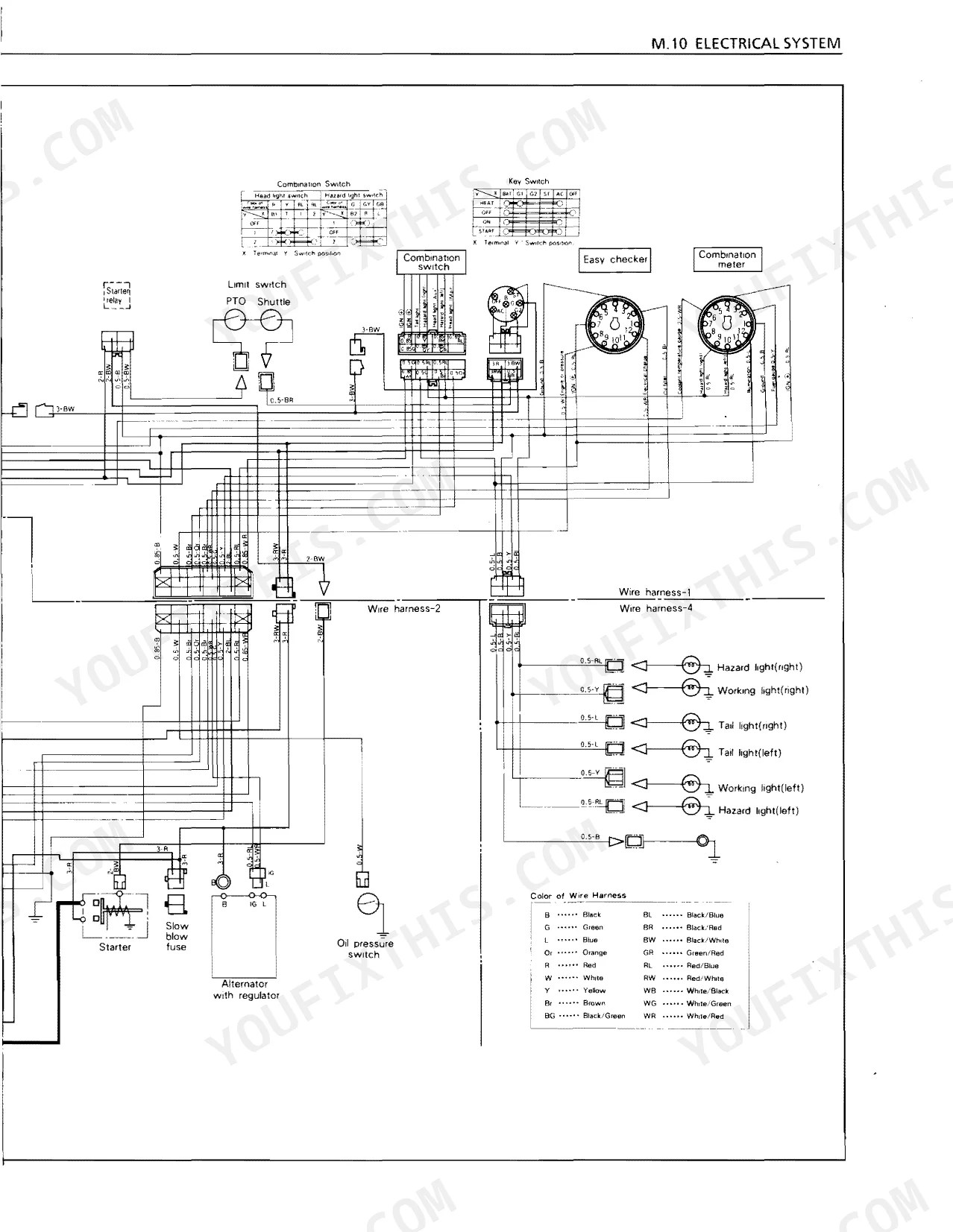
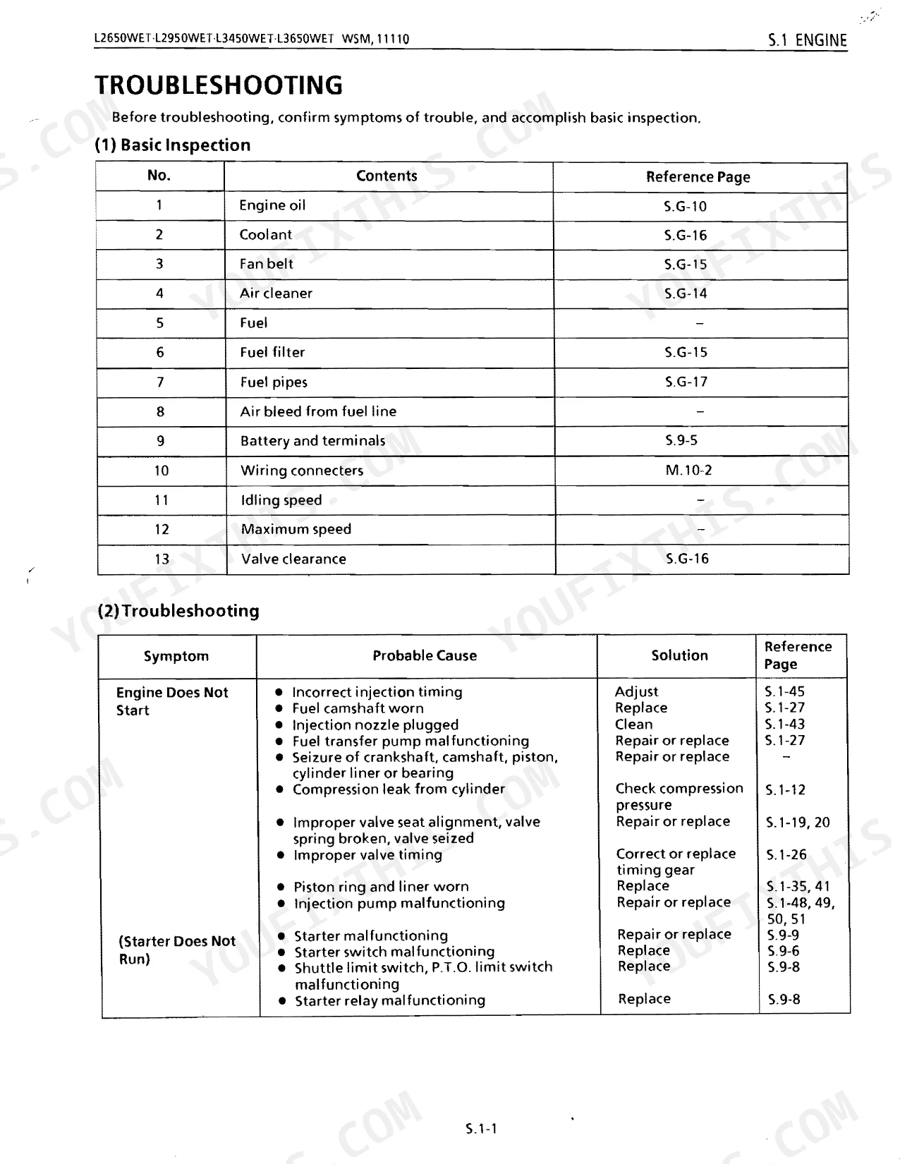
| Sect 9 Electrical | - | Basic Inspection, Fuse Blown Frequently, Battery Discharges Too Quickly, Starter Motor Does Not Operate, Engine Key Switch Shut-Off System, Engine Does Not Start, Charging System, Lighting System |
| Supplement L3650Gst | - | Specifications, Dimensions |
Every system also includes tightening torques.
Quick Reference Specifications
| Specification | Value | Page |
|---|---|---|
| Hydraulic system reset procedure | Not found as a single 'reset' procedure. Bleeding procedure for power steering hydraulic system is described. | p. 263 |
| Cylinder head bolts torque | 83.4 to 88.3 N·m | p. 143 |
| Front wheel mounting bolt and nut torque | 124 to 147 N·m | p. 122 |
| Rear wheel mounting bolt and nut torque | 197 to 226 N·m | p. 122 |
| Front axle bracket mounting bolts Front (Thread size: 14 mm, 0.55 in. DIA.) torque | 123.6 to 147.1 N·m | p. 239 |
| Front axle bracket mounting bolts Rear (Thread size: 12 mm, 0.47 in. DIA.) torque | 103.0 to 117.7 N·m | p. 239 |
| Clutch Pedal Free play | 20 to 30 mm | p. 191 |
| Clutch Brake Disc Thickness | 1.9 to 2.1 mm | p. 191 |
| Clutch Housing Gear Backlash | 0.1 to 0.2 mm | p. 199 |
| Clutch Housing Shift Fork to Shifter Groove Clearance | 0.20 to 0.40 mm | p. 199 |
| Oil filter degree of filtration | 150 mesh | p. 50 |
| Hydraulic Pump Delivery at No Pressure | 29.5 ℓ/min | p. 275 |
Kubota L2650–L3650 Series Common Problems This Manual Covers
Kubota L3650GST wet clutch slipping under load, gears clashing on the shift, and the tractor hesitating off the line
Inspect the linkage and clutch pedal free play first. Adjust the linkage to hold 20 to 30 mm of free play as shown on page 191. If the slip persists, pull the clutch assembly and measure the main discs, replacing any that fall below the 21.1 mm allowable limit on page 196.
Manual Section: Sect 2 Clutch p. 190Three-point hitch lifting weakly, draft control acting erratic, and hydraulic oil running hot
Drain the hydraulic fluid and inspect the pump suction lines. Pull the hydraulic filter and confirm the 150 mesh screen on page 50 is clear of debris. Work through the troubleshooting steps on page 274 to isolate valve blockages before you test relief pressure, then clean every valve spool.
Manual Section: Hydraulic System Troubleshooting p. 274Rough idle, down on power, discolored exhaust, and the engine overheating fast under load
Test compression and check the cooling system. Turn to page 134 to match the exhaust symptoms to a cause. If you suspect a blown head gasket, lift the cylinder head, and on reassembly torque the head bolts to 83.4 to 88.3 N·m as specified on page 143.
Manual Section: Engine Troubleshooting p. 134Front wheels wandering, steering shimmy, and noise from the front axle housing through turns
Raise the front end and check the wheel bearings for play. Inspect the front axle bracket mounting bolts and torque the front 14 mm bracket bolts to 123.6 to 147.1 N·m as detailed on page 239. If the wheels still vibrate, walk the diagnostic tree on page 236.
Manual Section: Front Axle Troubleshooting p. 236Frequently Asked Questions
What are the torque specs for Kubota L2650WET/L2950WET/L3450WET/L3650WET GST?
Three GST transmission fasteners carry specified torques. The side cover mounting bolt takes 42.2 N·m (4.3 kgf·m, 31.1 ft-lbs); the Hi-Lo shift spool valve mounting bolt takes 17.7 N·m (1.8 kgf·m, 13.0 ft-lbs); and the mid case and transmission mounting nut tightens to 77.5 to 90.2 N·m (7.9 to 9.2 kgf·m, 57.1 to 66.5 ft-lbs). p. 380
What are the replacement specifications for clutch components?
Each clutch wear part has an allowable thickness limit. The clutch brake disc runs 1.9 to 2.1 mm (0.075 to 0.083 in.), the clutch disc 1.7 to 1.9 mm (0.067 to 0.075 in.), and the clutch disc plate 1.15 to 1.25 mm (0.045 to 0.049 in.). Measure below any of these and the part needs replacing. p. 191
What are the replacement specifications for transmission components?
The clutch pack has three wear-limited parts to check. The clutch disk bottoms out at 2.0 mm (0.0787 in.), the steel plate 1.2 at 0.95 mm (0.0374 in.), and the spring free length at 17.4 mm (0.685 in.). Past any of these, replace the part. p. 379
What do I get after purchasing this Kubota L2650–L3650 Series manual?
Download starts the moment payment clears. The full 394-page searchable service manual is yours to open on a laptop, tablet, or phone right in the shop.
Are there any print restrictions on this manual?
No restrictions at all. Print individual pages, full chapters, or the entire manual. The PDF is completely unlocked.
Are there hydraulic schematics in this Kubota L2650–L3650 Series manual?
Included. Hydraulic system schematics cover all circuits, control valves, and component specifications for the Kubota L2650–L3650 Series.

Reviews
There are no reviews yet.