


Need the factory part numbers for your Kubota L2900F tractor? This 312-page Kubota L2900F parts catalog PDF maps every component to its OEM reference through exploded views organized by system across the full machine. Inside: 140 pages of itemized parts lists spanning engine internals from injection pump component parts to nozzle holder internals, clutch and all transmission variants, hydraulic pump and control valve assemblies, steering cylinder components, 3-point linkage, and the full electrical system. Factory-listed weights travel with every part number: the crankcase assembly at 48.5 kgf, the flywheel at 25.7 kgf. Called the dealer with the wrong number before? Search by keyword, jump to any system via bookmarks, and read the exact OEM part number off your screen before you dial.
What's Inside This Kubota L2900F Parts Manual
| System | Pages | Key Topics |
|---|---|---|
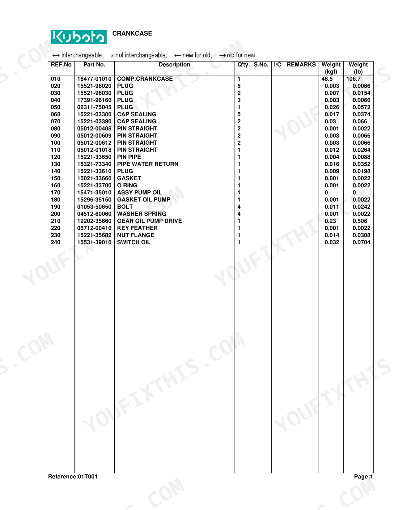
| Crankcase | 6-7 | Comp.Crankcase, Plug, Cap Sealing, Pin Straight, Pin Pipe, Pipe Water Return, Gasket, O Ring |
| Piston and Crankshaft | 10-11 | Piston, Assy Piston Ring, Pin Piston, Clip Piston Pin, Assy Connecting Rod, Bush Piston Pin, Bolt Connecting Rod, Metal Crankpin |
| Main Bearing Case | 12-13 | Assy Case Main Brg., Bolt Bearing Case, Gasket Brg.Case, Cover Bearing Case, Gasket Brg.Case Cov., Bolt, Seal Oil |
| Flywheel [W/O Ind-Pto] | 14-16 | Comp.Flywheel, Gear Ring, Bolt Flywheel, Comp.Housing F-W, Pin Straight, Plug, Cover, Packing Cover |
| Flywheel [With Ind-Pto] | 17-19 | Comp.Flywheel, Gear Ring, Bolt Flywheel, Hub Spline, Comp.Housing F-W, Pin Straight, Plug, Cover |
| Cylinder Head | 20-21 | Hook Engine, Cap Protector, Stud, Nut, Washer Spring, Washer Plain, Comp.Cylinder Head, Cap Sealing |
| Valve and Rocker Arm | 22-24 | Valve Inlet, Valve Exhaust, Spring Valve, Retainer Valve Sp., Collet Valve Spring, Seal Valve Stem, Cap Valve, Assy Shaft R-Arm |
| Nozzle Holder/Glow Plug | 25-27 | Assy Pipe Over Flow, Assy Tube Fuel, Clip Pipe, Tube Fuel, Kit Holder Nozzle, Gasket, Seal Heat, Pipe Injection |
| Nozzle Holder [Component Parts] | 28-29 | Assy Holder Nozzle, Nut, Washer Adjusting, Spring Nozzle, Piece Distance, Push Rod, Nut Nozzle, Washer |
| Cylinder Head Cover | 30-31 | Plate B/Ther Element, Element Breather, Oil Shield Breather, Screw with Washer, Joint Breather, Cover Cyl.Head, Gasket Head Cover, Nut Cap |
| Inlet Manifold | 32-33 | Manifold Inlet, Gasket In-Manifold, Bolt |
| Gear Case | 36-37 | Assy Case Gear, Plug, O Ring, Pin Start Spring, Pin Straight, Support Oil Filter, Gasket, Bolt |
| Water Pump | 38-39 | Assy Pump Water, Body Water Pump, Bearing, Impeller Water Pump, Impeller, Assy Seal Mechanical, Flange Water Pump, Gasket Water Pump |
| Water Flange and Thermostat | 40-41 | Comp.Flange Water, Pipe Water Return, Gasket Water Flange, Bolt, Stud, Nut, Washer Spring, Band Pipe |
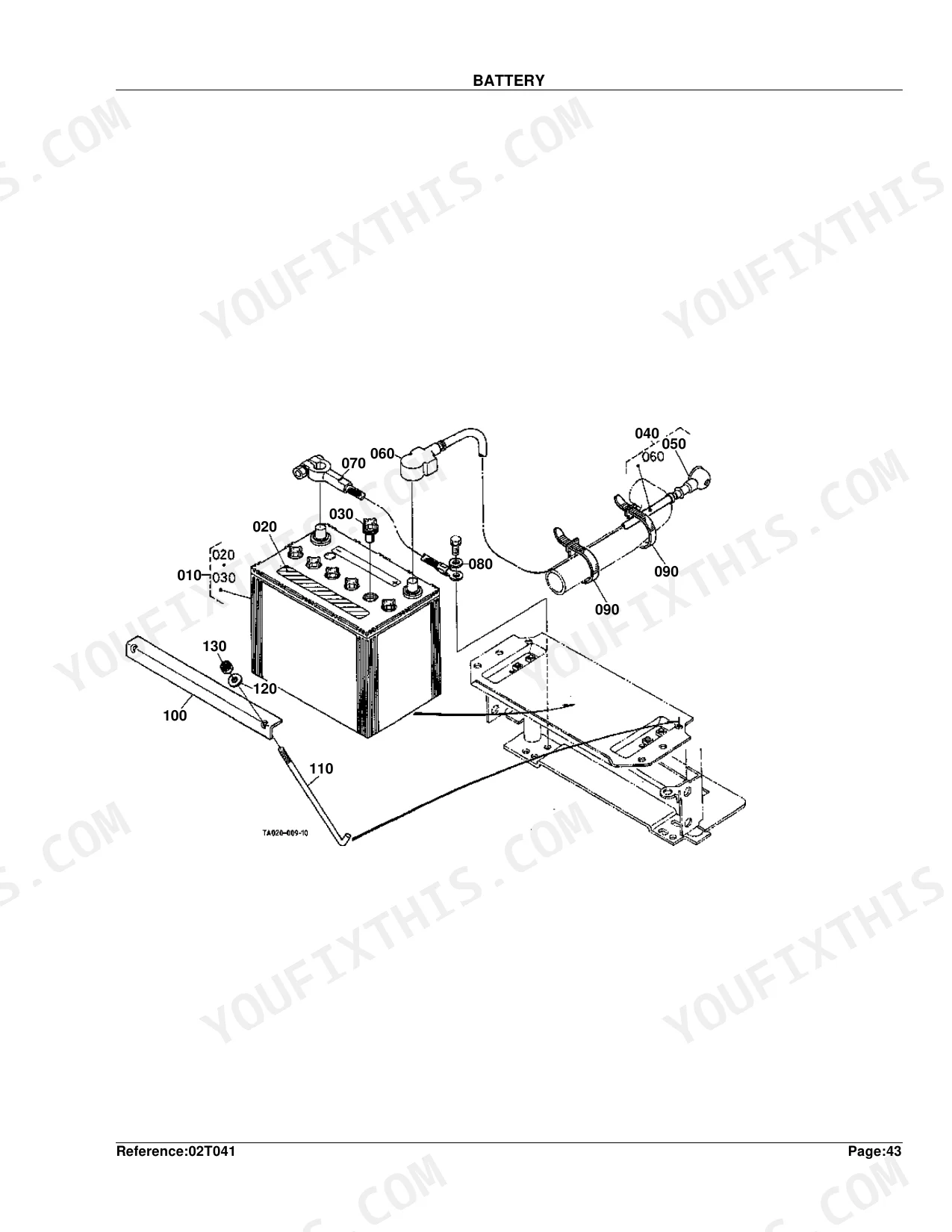
| Fuel Camshaft | 42-43 | Assy Camshaft Fuel, Camshaft Fuel, Bearing Ball, Gear Injection Pump, Key Feather, Circlip External, Sleeve Governor, Cir-Clip Gov. Sleeve |
| Injection Pump | 44-45 | Assy Pump Injection, Shim Injection, Bolt, Stud, Nut, Washer Spring, Assy Cock Jet Start, Assy Pump Fuel |
| Injection Pump [Component Parts] | 46-47 | Assy Pump Injection, Plunger Pump, Valve Delivery, Spring Deliv.Valve, Gasket Deliv.Valve, Holder Deliv.Valve, Assy Plate Lock, Assy Tappet |
| Engine Stop Lever | 48-49 | Apparatus Idling, Assy Bolt Adjustment, Nut, Nut Cap, Gasket, Cap, Assy Lever Eng.Stop, Cover Injection Pump |
| Speed Control Plate | 50-51 | Bolt Adjusting, Nut, Gasket, Nut Cap, Cap, Lever Speed Control, Key Feather, O Ring |
| Governor | 52-53 | Comp.Lever Governor, Assy Lever Fork, Shaft Fork Lever, Bolt Lever Shaft, Washer Spring, Holder Fork Lever, Bolt, Washer Plain |
| Upper Gasket Kit | 54-55 | Kit Gasket Upper, O Ring, Gasket Cyl.Head, Seal Valve Stem, Gasket, Seal Heat, Gasket Head Cover, Gasket In-Manifold |
| Lower Gasket Kit | 56-57 | Kit Gasket Lower, Gasket, Gasket Oil Pump, Gasket Oil Pan, O Ring, Seal Oil, Gasket Brg.Case, Gasket Brg.Case Cov. |
| Air Cleaner | 58-59 | Assy Cleaner Air, Comp.Body A/C, Pipe Air Cleaner, Comp.Filter A/C, Assy Cup Air Cleaner, Bolt Wing, Seal Washer, Label Air Cleaner |
| Double Air Cleaner [Option] | 60-61 | Assy Cleaner Air, Assy Body A/C, Assy Element Inner, Assy Element Outer, Assy Cover A/C, Valve Evacuator, Assy Indicator, Stay Air Cleaner |
| Exhaust Manifold and Muffler | 62-63 | Manifold Exhaust, Gasket Muffler, Stud, Gasket Ex-Manifold, Washer Spring, Nut, Muffler, Bolt |
| Stop Solenoid and Engine Stop Wire | 64-66 | Solenoid Stop, Bolt, Lever Stop, Washer Plain, Pin Snap, Wire Engine Stop, Screw, Holder Wire |
| Accelerator Lever | 67-68 | Grip, Shaft Accel.Control, Support Accel.Lever, Bolt Flange, Washer Plain, Cap Spring, Spring Accel.Lever, Nut |
| Accelerator Linkage | 69-70 | Spring, Rod Accel., Washer Plain, Pin Split, Lever Accel |
| Accelerator Rod | 71-72 | Rod Pedal, Washer Plain, Pin Split, Assy Rod Accel., Nut |
| Fuel Tank | 73-74 | Assy Tank Fuel, Assy Cap Fuel Tank, Gasket Tank Cap, Cushion Battery, Bolt Flange, Washer Plain, Cushion, Spacer |
| Fuel Pipe and Fuel Filter | 75-76 | Assy Filter Fuel, Assy Tube Fuel, Clip Pipe, Tube, Tube Fuel, Assy Pipe Fuel, Bolt, Band Pipe |
| Fuel Filter [Component Parts] | 77-78 | Assy Filter Fuel, Assy Body, Handle Filter, Gasket, Retainer Handle, Plate Thrust, O Ring, Screw |
| Water Pipe | 81-82 | Pipe Water, Band, Hose, Hose Drain, Band Hose, Band Pipe, Band Cord |
| Radiator | 83-84 | Assy Radiator, Shroud Fan, Cap Radiator, Plug Drain, O Ring, Guide, Bolt, Net Radiator |
| Reserve Tank | 85-86 | Tank Reserve, Cap, Gasket, Pipe Water Overflow, Clip Pipe, Label Caution, Stay Reserve Tank, Bolt Flange |
| Alternator | 87-89 | Stay Dynamo, Pulley Fan Drive, Key Feather, Assy Alternator, Bolt, Nut, Washer Spring, Washer Plain |
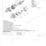
| Alternator [Component Parts] | 90-91 | Assy Alternator, Pulley Alternator, Nut, Collar, Rotor, Cover Bearing, Bearing Ball, Washer Thrust |
| Starter | 92-93 | Assy Starter, Stud, Nut, Bolt, Washer Spring |
| Starter [Component Parts] | 94-95 | Assy Starter, Yoke, Armature, Bearing, Assy Clutch, Roller, Retainer, Gear |
| Switch | 98-99 | Timer Key Stop, Controller, Relay Glow, Bolt Flange, Nut Flange, Sensor Thermo, Gasket, Lever |
| Panel Board | 100-101 | Panel Board Overview, Panel Board Exploded View, Panel Board Parts List |
| Panel Board [Component Parts] | 102-103 | Panel Board Component Parts Overview, Panel Board Component Parts Exploded View, Panel Board Component Parts Parts List |
| Light | 104-105 | Light Overview, Light Exploded View, Light Parts List |
| Electrical Wiring | 106-107 | Electrical Wiring Overview, Electrical Wiring Exploded View, Electrical Wiring Parts List |
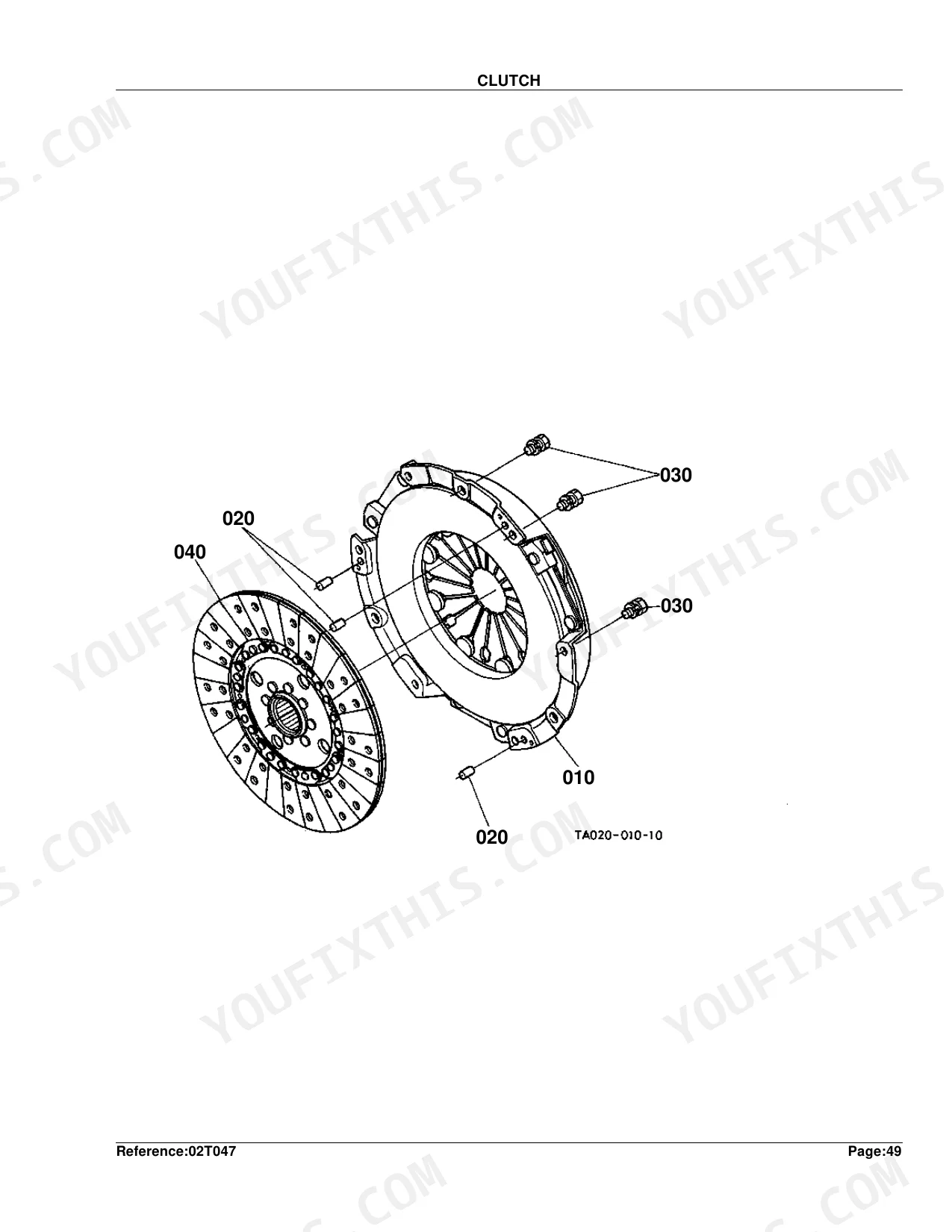
| Clutch | 108-109 | Clutch Overview, Clutch Exploded View, Clutch Parts List |
| Clutch Lever | 110-111 | Clutch Lever Overview, Clutch Lever Exploded View, Clutch Lever Parts List |
| Clutch Pedal | 112-113 | Component Detail |
| Clutch Housing [Manual T/M Type] | 114-116 | Manual T/M Type Component Detail |
| Mid Case [Manual T/M Type] [With Ind-Pto] | 117-119 | Manual T/M Type With Ind-Pto Component Detail |
| Transmission Case | 120-121 | Transmission Case Overview, Transmission Case Exploded View, Transmission Case Parts List |
| Main Shaft [With Ind-Pto] | 122-123 | Main Shaft With Ind-Pto Overview, Main Shaft With Ind-Pto Exploded View, Main Shaft With Ind-Pto Parts List |
| Countershaft | 124-125 | Countershaft Overview, Countershaft Exploded View, Countershaft Parts List |
| Shuttle Shaft [Manual T/M Type] | 126-127 | Shuttle Shaft Manual T/M Type Overview, Shuttle Shaft Manual T/M Type Exploded View, Shuttle Shaft Manual T/M Type Parts List |
| Range Gear Shaft [Manual T/M Type] | 128-129 | Range Gear Shaft Manual T/M Type Overview, Range Gear Shaft Manual T/M Type Parts List |
| PTO Countershaft [With Ind-Pto] | 130-131 | Pto Countershaft With Ind-Pto Overview, Pto Countershaft With Ind-Pto Exploded View, Pto Countershaft With Ind-Pto Parts List |
| PTO Clutch [With Ind-Pto] | 132-133 | Pto Clutch With Ind-Pto Overview, Pto Clutch With Ind-Pto Exploded View, Pto Clutch With Ind-Pto Parts List |
| PTO Shaft [W/O Mid-Pto] | 134-136 | W/O Mid-Pto Component Detail |
| PTO Shaft [With Mid-Pto] | 137-139 | With Mid-Pto Component Detail |
| Mid PTO [With Mid-Pto] | 140-141 | Mid Pto With Mid-Pto Overview, Mid Pto With Mid-Pto Exploded View, Mid Pto With Mid-Pto Parts List |
| Main Gear Shift Lever [Manual T/M Type] | 142-144 | Component Detail |
| Main Gear Shift Fork [Manual T/M Type] | 145-146 | Main Gear Shift Fork, Fork Main Shift, Fork Shift, Rod Fork, Pin Spring, Ball, Bolt, Washer Spring |
| Shuttle Shift Lever | 147-149 | Component Detail |
| Shuttle Shift Fork [Manual T/M Type] | 150-151 | Shuttle Shift Fork Manual T/M Type Overview, Shuttle Shift Fork Manual T/M Type Parts List |
| Range Gear Shift Lever [Manual T/M Type] [W/O Creep] | 152-153 | Laver Range Shift, Pin Spring, Rod, Washer Plain, Pin Split, Pin Snap, Grip Lever, Shaft Fulcrum |
| Range Gear Shift Lever/Creep Gear Shift Lever [Manual T/M Type] [With Creep] | 154-156 | Manual T/M Type With Creep Component Detail |
| Range Gear Shift Fork and Creep Gear Shift Fork [Manual T/M Type] | 157-158 | Range Gear Shift Fork, Creep Gear Shift Fork, Rod Fork, Arm Range Shift, Arm Shift |
| Mid PTO Shift Lever [With Mid-Pto] | 159-160 | Mid Pto Shift Lever With Mid-Pto Overview, Mid Pto Shift Lever With Mid-Pto Parts List |
| PTO Clutch Control Lever [With Ind-Pto] | 161-163 | With Ind-Pto Component Detail |
| Spiral Bevel Pinion [W/O Creep] | 164-165 | Spiral Bevel Pinion W/O Creep Overview, Spiral Bevel Pinion W/O Creep Exploded View, Spiral Bevel Pinion W/O Creep Parts List |
| Spiral Bevel Pinion and Creep [With Creep] | 166-167 | Spiral Bevel Pinion, Creep, Gear-shaft, Bearing Taper-roller, Bearing Roller, Collar Thrust, Bearing Needle, Bearing Ball |
| Rear Differential | 168-169 | Rear Differential Overview, Rear Differential Exploded View, Rear Differential Parts List |
| Defferential Lock Shift Fork | 170-171 | Component Detail |
| Rear Axle | 172-173 | Rear Axle Overview, Rear Axle Exploded View, Rear Axle Parts List |
| Rear Wheel (11.2-24) | 174-175 | Rear Wheel (11.2-24) Overview, Rear Wheel (11.2-24) Exploded View, Rear Wheel (11.2-24) Parts List |
| Rear Wheel (12.4-24) | 176-177 | Rear Wheel (12.4-24) Overview, Rear Wheel (12.4-24) Exploded View, Rear Wheel (12.4-24) Parts List |
| Rear Wheel (13.6-16) | 178-179 | Rear Wheel (13.6-16) Overview, Rear Wheel (13.6-16) Exploded View, Rear Wheel (13.6-16) Parts List |
| Rear Wheel (41X14.00-20) | 180-181 | Rear Wheel (41X14.00-20) Overview, Rear Wheel (41X14.00-20) Exploded View, Rear Wheel (41X14.00-20) Parts List |
| Rear Wheel (355/80-D20) | 182-183 | Rear Wheel (355/80-D20) Overview, Rear Wheel (355/80-D20) Exploded View, Rear Wheel (355/80-D20) Parts List |
| Brake | 184-185 | Brake Overview, Brake Exploded View, Brake Parts List |
| Brake Pedal | 186-188 | Component Detail |
| Brake Rod 1 | 189-190 | Brake Rod 1 Overview, Brake Rod 1 Exploded View, Brake Rod 1 Parts List |
| Brake Rod 2 | 191-192 | Brake Rod 2 Overview, Brake Rod 2 Exploded View, Brake Rod 2 Parts List |
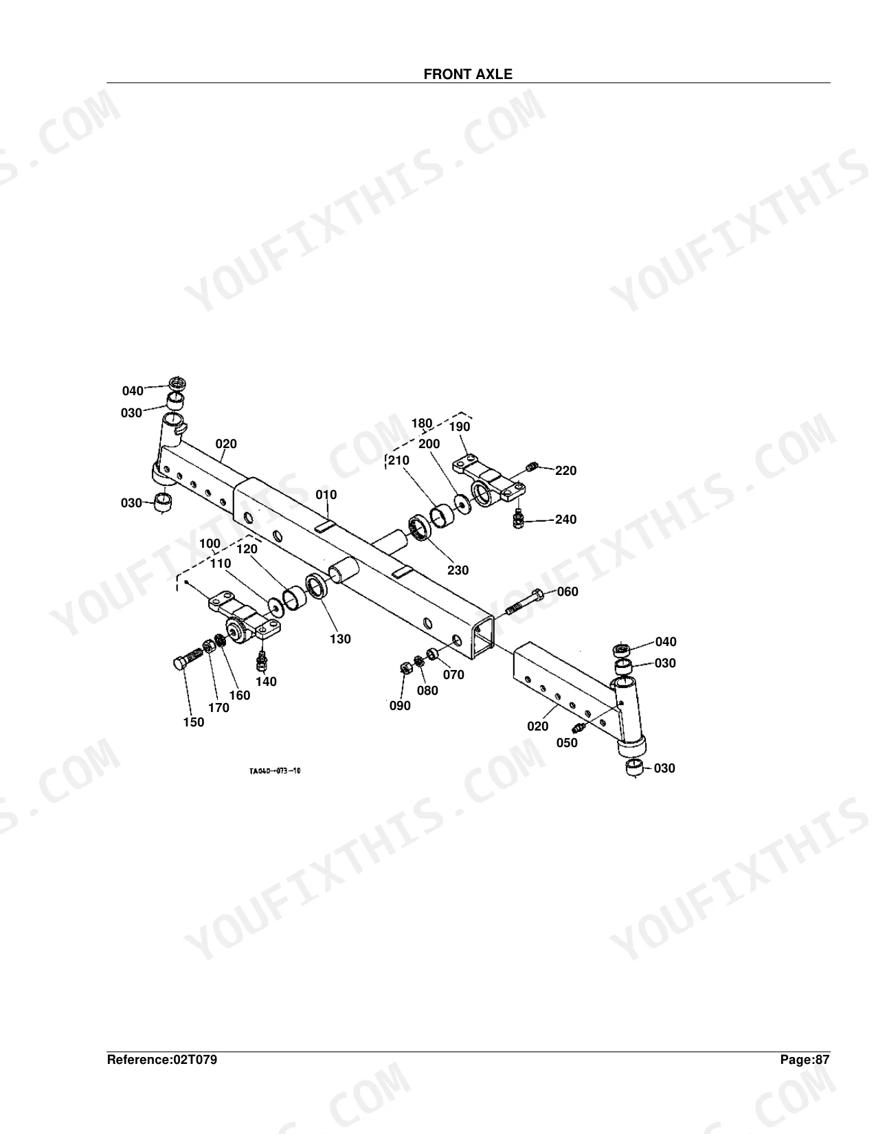
| Front Axle | 193-194 | Front Axle Overview, Front Axle Exploded View, Front Axle Parts List |
| Knuckle Shaft | 195-196 | Knuckle Shaft Overview, Knuckle Shaft Exploded View, Knuckle Shaft Parts List |
| Front Wheel (5.00-15) | 197-198 | Front Wheel (5.00-15) Overview, Front Wheel (5.00-15) Exploded View, Front Wheel (5.00-15) Parts List |
| Front Wheel (23*8.50-12) | 199-200 | Front Wheel (23*8.50-12) Overview, Front Wheel (23*8.50-12) Exploded View, Front Wheel (23*8.50-12) Parts List |
| Front Wheel (25*8.50-14) | 201-202 | Front Wheel (25*8.50-14) Overview, Front Wheel (25*8.50-14) Exploded View, Front Wheel (25*8.50-14) Parts List |
| Front Axle Frame [2Wd] | 203-204 | Front Axle Frame 2WD Overview, Front Axle Frame 2WD Exploded View, Front Axle Frame 2WD Parts List |
| Front Wheel Drive Shaft | 205-206 | Front Wheel Drive Shaft Overview, Front Wheel Drive Shaft Exploded View, Front Wheel Drive Shaft Parts List |
| Steering Linkage [2Wd] | 207-208 | Steering Linkage 2WD Overview, Steering Linkage 2WD Exploded View, Steering Linkage 2WD Parts List |
| Steering Cylinder | 209-211 | Component Detail |
| Steering Cylinder [Component Parts] | 212-214 | Component Parts Component Detail |
| Steering Controller | 215-216 | Steering Controller Overview, Steering Controller Exploded View, Steering Controller Parts List |
| Steering Handle | 217-218 | Steering Handle Overview, Steering Handle Exploded View, Steering Handle Parts List |
| Hydraulic Oil Line (Ps) | 219-221 | Ps Component Detail |
| Regulator Valve | 222-223 | Regulator Valve Overview, Regulator Valve Exploded View, Regulator Valve Parts List |
| PTO Hydraulic Oil Line [With Ind-Pto] [Manual T/M Type] | 224-225 | Assy Bolt Orifice, Gasket, Comp.pipe I-pto, Bolt Joint, Clamp, Pipe Rubber |
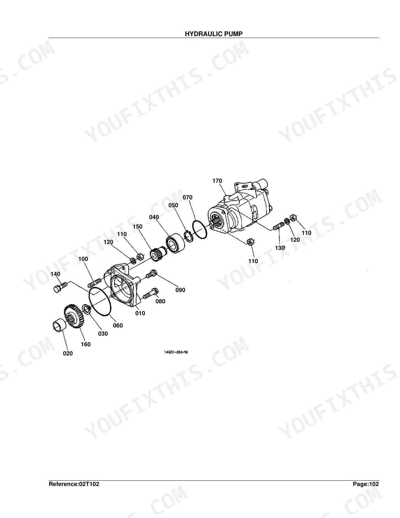
| Hydraulic Pump | 226-227 | Hydraulic Pump Overview, Hydraulic Pump Exploded View, Hydraulic Pump Parts List |
| Hydraulic Pump [Component Parts] | 228-229 | Hydraulic Pump Component Parts Overview, Hydraulic Pump Component Parts Exploded View, Hydraulic Pump Component Parts Parts List |
| Hydraulic Oil Line (Inlet) | 230-232 | Inlet Component Detail |
| Hydraulic Oil Line (Delivery) | 233-234 | Hydraulic Oil Line Delivery Overview, Hydraulic Oil Line Delivery Exploded View, Hydraulic Oil Line Delivery Parts List |
| Hydraulic Outlet Block | 235-236 | Hydraulic Outlet Block Overview, Hydraulic Outlet Block Exploded View, Hydraulic Outlet Block Parts List |
| Hydraulic Cylinder | 237-239 | Component Detail |
| Lift Arm | 240-241 | Lift Arm Overview, Lift Arm Exploded View, Lift Arm Parts List |
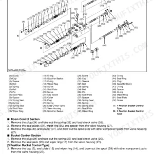
| Control Valve | 242-244 | Component Detail |
| Control Valve [Component Parts] | 245-246 | Control Valve Component Parts Overview, Control Valve Component Parts Exploded View, Control Valve Component Parts Parts List |
| Feed Back Lever | 247-248 | Feed Back Lever Overview, Feed Back Lever Exploded View, Feed Back Lever Parts List |
| Position Control Lever | 249-251 | Component Detail |
| Draft and Position Control Lever 1 [Option] | 252-253 | Link Control, Pin Spring, Bush, Shaft Draft, Washer Plain, Spring Plate, Nut, Link Draft |
| Draft and Position Control Lever 2 [Option] | 254-255 | Stay, Bolt, Bush, Shaft Draft, Gasket, Washer Plain, Spring Plate, Nut |
| Top Link Holder [Option] | 256-257 | Top Link Holder Option Overview, Top Link Holder Option Exploded View, Top Link Holder Option Parts List |
| Drawbar and PTO Protector | 258-260 | Component Detail |
| Swinging Drawbar and Clevis Drawbar [Option] | 261-262 | Frame Swing Drawbar, Bolt, Washer Spring, Pin Joint, Pin Snap, Manual Assembly, Drawbar, Hitch Drawbar |
| Remote Control Valve Lever 1 [Option] | 263-264 | Assy Valve Aux.con., Cover Aux.cont.valve, Assy Pipe Cont.valve, O Ring, Washer Spring, Pipe Return, Lever Aux.con.valve, Grip Lever |
| Remote Control Valve Lever 2 [Option] | 265-266 | Assy Valve Aux.con., Cover Aux.cont.valve, Assy Pipe Cont.valve, O Ring, Bolt, Washer Spring, Pipe Return, Lever Aux.con.valve |
| Remote Control Valve Lever 3 [Option] | 267-268 | Assy Valve Aux.con., Cover Aux.cont.valve, Assy Pipe Cont.valve, Pipe Return, Lever Aux.con.valve, Tube Lever, Grip Lever, Stay Aux.cont.valve |
| Remote Control Valve Coupler 1 [Option] | 269-270 | Remote Control Valve Coupler, Adapter, Hose Aux.cont.valve, Assy Coupler Female, Plug Coupler, Support Coupler, Assy Coupler Male, Stay Coupler |
| Remote Control Valve Coupler 2 [Option] | 271-272 | Adapter, O Ring, Hose Aux.cont.valve, Assy Coupler Female, Plug Coupler, Support Coupler, Cir Clip Internal, Bolt |
| Remote Control Valve Coupler 3 [Option] | 273-274 | Adapter, O Ring, Hose Aux.cont.valve, Assy Coupler Female, Plug Coupler, Support Coupler, Cir Clip Internal, Bolt |
| 3-Point Linkage 1 (Lower Link) | 275-276 | 3-Point Linkage 1 Lower Link Overview, 3-Point Linkage 1 Lower Link Exploded View, 3-Point Linkage 1 Lower Link Parts List |
| 3-Point Linkage 2 (Lift Rod) | 277-278 | 3-Point Linkage 2 Lift Rod Overview, 3-Point Linkage 2 Lift Rod Exploded View, 3-Point Linkage 2 Lift Rod Parts List |
| Front Grille | 279-281 | Component Detail |
| Front Grille Support | 282-283 | Front Grille Support Overview, Front Grille Support Exploded View, Front Grille Support Parts List |
| Hood (Bonnet) | 284-286 | Bonnet Component Detail |
| Side Cover | 287-289 | Component Detail |
| Side Cover Lower | 290-291 | Side Cover Lower Overview, Side Cover Lower Exploded View, Side Cover Lower Parts List |
| Shutter Plate | 292-294 | Component Detail |
| Panel Frame | 295-296 | Panel Frame Overview, Panel Frame Exploded View, Panel Frame Parts List |
| Fender | 297-298 | Fender Overview, Fender Exploded View, Fender Parts List |
| Floor Seat | 299-301 | Component Detail |
| Seat | 302-303 | Component Detail |
| Step | 304-305 | Step Overview, Step Exploded View, Step Parts List |
| ROPS | 306-307 | Component Detail |
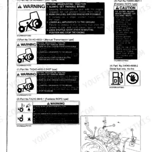
| Label 1 | 308-309 | Component Detail |
| Label 2 | 310-311 | Component Detail |
| Accessories and Service Parts | 312 | Accessories And Service Parts Overview, Accessories And Service Parts Exploded View, Accessories And Service Parts Parts List |
Quick Reference Specifications
| Specification | Value | Page |
|---|---|---|
| COMP.CRANKCASE Weight | 48.5 kgf | p. 7 |
| COMP.FLYWHEEL Weight | 25.7 kgf | p. 16 |
| ASSY CAMSHAFT Weight | 3.42 kgf | p. 35 |
| ASSY CASE GEAR Weight | 4.2 kgf | p. 37 |
| ASSY PUMP WATER Weight | 1.21 kgf | p. 39 |
| ASSY RADIATOR Weight | 5.9 kgf | p. 84 |
| ASSY ALTERNATOR Weight | 2.85 kgf | p. 89 |
| ASSY STARTER Weight | 3.4 kgf | p. 93 |
| CORD BATTERY Weight | 0.55 kgf | p. 97 |
| ASSY PLATE PRESSURE Weight | 6.5 kgf | p. 109 |
| CLUTCH HOUSING Weight | 41 kgf | p. 116 |
| ASSY REAR WHEEL Weight | 133 kgf | p. 183 |
Kubota L2900F Common Problems This Manual Covers
Kubota L2900F intermittent hard start or clicking noise when turning the key in cold weather. p. 94
Check the starter component parts breakdown on page 94. Identify the exact replacement part numbers for the armature, internal bearings, or the complete starter assembly. The full ASSY STARTER weighs exactly 3.4 kgf, so support it carefully when unbolting it from the engine block to avoid dropping it.
Manual Section: Starter [Component Parts]Positive pressure and light oil haze blowing out of the valve cover breather line. p. 30
Inspect the cylinder head cover parts diagram on page 30. Find the correct part numbers for the breather element, joint breather, and cylinder head cover gasket. Replace the clogged element before it forces leaks at the crankcase, which weighs 48.5 kgf and requires a major teardown.
Manual Section: Cylinder Head CoverEngine overheating under heavy load with visible coolant dripping from the front timing cover area. p. 38
Review the water pump exploded view on page 38. Locate the replacement part numbers for the mechanical seal, impeller, and water pump gasket. Order the complete assembly if the housing is cracked. The ASSY PUMP WATER weighs 1.21 kgf, making it easy to swap out once drained.
Manual Section: Water PumpGrinding gears or extreme difficulty shifting between ranges while the tractor is running. p. 114
Examine the manual transmission clutch housing diagram on page 114. Find the proper part numbers for the pressure plate, release bearings, and associated hardware. If replacing the entire housing, prepare a floor jack because the bare CLUTCH HOUSING weighs 41 kgf and requires heavy support during splitting.
Manual Section: Clutch Housing [Manual T/M Type]Frequently Asked Questions
What are the replacement specifications for steering seals?
The manual provides part numbers and weights for steering-related seals and gaskets, but not detailed replacement specifications such as dimensions or material properties. For example, the 'SEAL OIL' for the front axle is part number 38240-13140, with a quantity of 2 and a weight of 0.004 kgf (0.0088 lb). Other related parts include 'GASKET ROD' (TA040-37560) and 'SEAL DUST' (TA040-37580) for the steering cylinder, each with specific part numbers and weights.
What are the replacement specifications for hydraulic hoses?
The manual lists part numbers and weights for various hydraulic hoses and pipes, but does not provide detailed replacement specifications such as pressure ratings, lengths, or material types. For instance, a 'HOSE DELIVERY' is part number 34530-33510, weighing 0 kgf (0 lb), and an 'ASSY HOSE RETURN' is part number 34030-33530, weighing 0.29 kgf (0.638 lb). A 'HOSE INLET' is identified by part number TA020-33340, with a weight of 0.065 kgf (0.143 lb).
Is this Kubota L2900F Parts Catalog a digital download?
Immediate download of the complete 312-page searchable Parts Catalog. Access it on any device — laptop at your desk or phone in the field.
Am I able to print pages from this Kubota L2900F manual?
Absolutely. No DRM or copy protection. Print the whole manual or just the pages you need. Any home or office printer works.
Document Quality
This is a scanned PDF document with an optical character recognition (OCR) layer, so you can search and copy the full text. The text quality is generally crisp and easy to read throughout the manual, including all labels on the diagrams. Illustrations are raster images, but they are clear and detailed, ensuring all components and their labels are easily identifiable. Pages are mostly clean with minimal scan artifacts, and there are no skewed or heavily marked pages. Please note that many pages contain only headers and footers, indicating no content in the main body.


Reviews
There are no reviews yet.