


Finding the correct replacement component before touching a wrench saves time and money. This Kubota LA681 Parts Catalog PDF delivers exploded-view drawings and numbered tables for every major loader system. The 31-page manual covers the main frame, side frame, boom, control valve, and hydraulic cylinders. Component-level breakdowns isolate specific items like spool caps, detent float kits, and seal kits so you order exactly what failed. Hardware is called out with precision: boom grease fittings are specified as 90-degree 1/4-28T.T. units, and main frame bolts are listed down to their thread pitch (M14*1.5*40). Bookmarked by system, this file lets you pull up the diagram, identify your part, and call the dealer counter in minutes.
What's Inside This Kubota LA681 Parts Manual
| System | Pages | Key Topics |
|---|---|---|
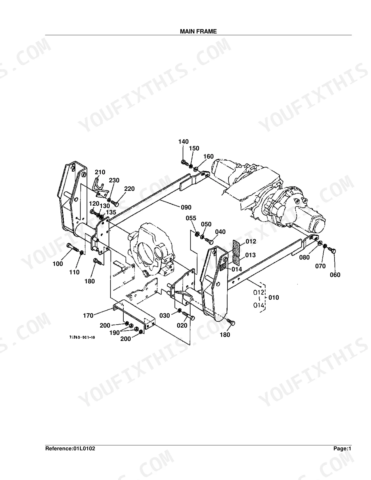
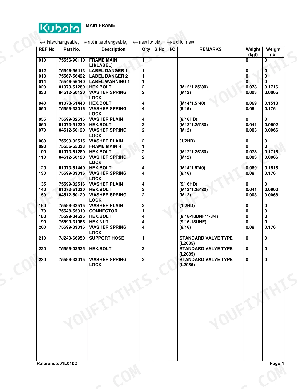
| Main Frame | 3-4 | Figure: MAIN FRAME, Table: Main Frame, Frame Main Lh, Label Danger 1, Hex.Bolt, Washer Spring Lock, Support Hose |
| Side Frame | 5-6 | Figure: SIDE FRAME, Table: Side Frame, Frame Side Lh, Label Danger 3, Hex.Bolt, Washer Spring Lock, Support Brace |
| Boom | 7-8 | Figure: BOOM, Table: BOOM, Stand Lh, Pin Spring Lock, Cir-Crip External, Fitting Grease, Hex.Bolt |
| Control Valve | 9-12 | Figure: Control Valve, Table: Control Valve, Stay Valve, Hex.Bolt, Washer Spring Lock, Valve Control, Assy Adapter 1 |
| Control Valve [Component Parts] | 13-16 | Figure: Control Valve [Component Parts], Table: Control Valve [Component Parts], Valve Control, Cap Spool, Kit Detent Float, Assy Shut-Off Plug, Plate-Seal |
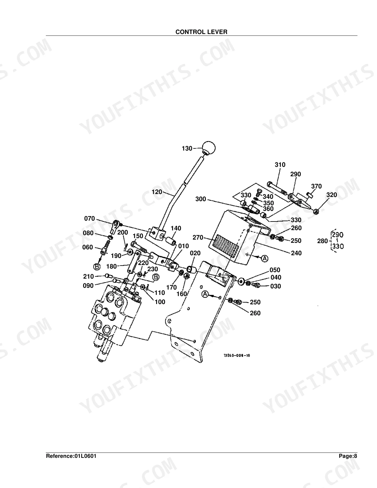
| Control Lever | 17-20 | Figure: Control Lever, Table: Control Lever, Lever, Bushing, Hex.Bolt, Grip Lever, Cushion Rubber, Cylinder / Hydraulic Hose |
| Cylinder (Boom) [Component Parts] | 23-24 | Figure: Cylinder [Component Parts], Table: Cylinder [Component Parts], Tube 1 Comp, Rod 1 Comp, Piston 1, Kit Seal |
| Cylinder (Bucket) [Component Parts] | 25-26 | Figure: Cylinder [Component Parts], Table: Cylinder [Component Parts], Tube 2 Comp, Rod 2 Comp, Piston 1, Plug |
| Hydraulic Tube | 27-28 | Figure: Hydraulic Tube, Table: Hydraulic Tube, Tube 1 Hydraulic, Tube 2 Hydraulic, Clamp 1, Hex.Bolt, Washer Spring Lock |
| Hydraulic Hose | 29-30 | Figure: Hydraulic Hose, Table: Hydraulic Hose, Assy Hose 4 Hyd, Nipple, Guard Hose, Coupler, Mark Orange |
| Accessories and Service Parts | 31 | Table: Accessories and Service Parts, Operator'S Manual, Workshop Manual, Flat-Rate Schedule |
Quick Reference Specifications
| Specification | Value | Page |
|---|---|---|
| Main Frame Hex Bolt Thread/Length (M12) | M12*1.25*80 | p. 4 |
| Main Frame Hex Bolt Thread/Length (M14) | M14*1.5*40 | p. 4 |
| Main Frame Hex Bolt Thread/Length (Imperial) | 9/16-18UNF*1-3/4 | p. 4 |
| Side Frame Hex Bolt Thread/Length (M16) | M16*1.5*50 | p. 6 |
| Boom Grease Fitting Angle | 90DEG. | p. 8 |
| Boom Grease Fitting Thread Size | 1/4-28T.T. | p. 8 |
| Boom Hex Bolt Thread/Length | 1/4-20UNC*2-1/4 | p. 8 |
| Boom Nut Thread | 1/4-20UNC | p. 8 |
| Control Lever Bushing Diameter x Length | 5/8*1.00 | p. 18 |
| Control Lever Cotter Pin Diameter x Length | 1/32*1/2 | p. 18 |
| Cylinder (Boom) Grease Fitting Thread | 1/8-27PTF | p. 24 |
| Cylinder (Boom) Nut Thread | 5/8-18UNFP | p. 24 |
Kubota LA681 Common Problems This Manual Covers
Kubota LA681 boom cylinder leaking, need correct seal kit part number before ordering p. 23
Identify the boom cylinder seal kit in the exploded view on page 23. The Kit Seal is listed separately from the Tube 1 Comp, Rod 1 Comp, and Piston 1 components. Confirm you have the correct tube assembly before ordering. The cylinder nut uses a 5/8-18UNFP thread per the parts list on page 24. Cross-reference the serial number range to guarantee compatibility with your unit.
Manual Section: Cylinder (Boom) [Component Parts]Can't identify correct control valve spool cap or detent float kit part number p. 13
Review the Control Valve Component Parts diagram on page 13. The Kit Detent Float, Cap Spool, Plate-Seal, and Assy Shut-Off Plug are each listed as individual line items in the tables on pages 13-16. Match your part visually to the exploded view before submitting an order, as these items are not interchangeable between valve configurations.
Manual Section: Control Valve [Component Parts]Hydraulic hose assembly number unclear, need to match orange-marked hoses to the parts list p. 29
Examine the Hydraulic Hose diagram on page 29. Hoses are cataloged by specific 'Assy Hose X Hyd' part numbers (e.g., REF.No 010 for Assy Hose 4 Hyd). The table on page 30 also lists various 'Mark' items (e.g., Mark Orange, REF.No 240) as separate components. Match each hose by its specific assembly number. If you need the protective sleeve, the Guard Hose part (REF.No 040) is listed in the same section.
Manual Section: Hydraulic HoseControl lever bushing worn out, need correct diameter and part number before placing order p. 17
Find the Control Lever exploded view on page 17. The bushing is dimensioned at 5/8*1.00 (diameter x length) per the parts list on page 18. While ordering, pull the cotter pin spec: 1/32*1/2. The pin is frequently discarded during teardown and not reused, so order both together to avoid a second parts run.
Manual Section: Control LeverBoom grease fitting thread size unknown, need correct spec to order a replacement p. 7
Verify the fitting spec in the Boom parts list on page 8 after checking the diagram on page 7. The replacement is a 90-degree grease fitting with a 1/4-28T.T. thread. Confirm the angle before ordering: a straight fitting will not clear the surrounding structure. This part is listed alongside the spring lock pin and circlip components.
Manual Section: BoomMain frame hardware mixed up during disassembly, need bolt specs to reorder correct sizes p. 3
Consult the Main Frame parts list on page 4. Three bolt sizes are used in this assembly: M12*1.25*80, M14*1.5*40, and 9/16-18UNF*1-3/4. Match each bolt to its position in the chassis diagram on page 3 before ordering. Confirm the correct spring lock washer is listed alongside each bolt, as washer sizes vary by location on the frame.
Manual Section: Main FrameFrequently Asked Questions
What format is this Kubota LA681 manual in?
A 31-page Parts Catalog in searchable PDF format, available the moment you complete checkout. View it on a computer, tablet, or phone with no shipping wait.
Are there any print restrictions on this Kubota LA681 manual?
There are no print restrictions. You can print as many copies as you want. Many mechanics print the section they need and bring it to the shop floor.
Document Quality
This document is a scanned PDF with an OCR layer, allowing you to search and copy text throughout. The text quality is generally crisp and readable across all pages, including the detailed parts lists. Diagrams and illustrations are raster images, which appear clear at normal viewing but may show some pixelation upon high zoom; labels within these diagrams are readable. The pages are clean, free from scan artifacts, stains, or skewed content. There are no notable blank or filler pages present.

Reviews
There are no reviews yet.