

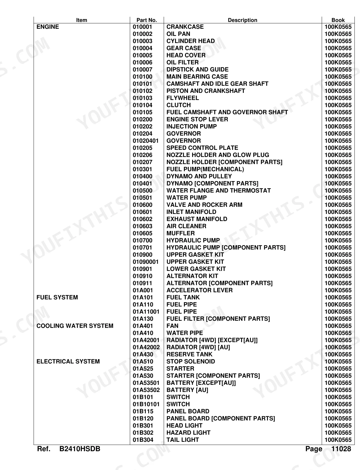


Every assembly on the B2410HSDB compact HST tractor is indexed across 368 bookmarked pages: engine internals, 4WD drivetrain, hydraulic system, and cab, right down to the Bi-Speed Turn clutch and control valve sub-components. Over 100 pages of parts lists supply OEM part numbers, quantities, and serial-number applicability. hydraulic parts diagrams trace each oil circuit from the suction pump through the HST loop, power steering pump, and 3-point lift cylinder. Engine coverage alone spans 35 pages, mapping the crankcase (32 kgf, page 8), injection pump, governor, nozzle holders, and both upper and lower gasket kits. Another 42 pages detail the drivetrain. Fuse ratings call out 5A, 10A, and 20A auto circuits alongside the 30A main, each with its matching Kubota part number. Bookmarked sections let you jump straight to any assembly, confirm the quantity, and place the order.
What's Inside This Kubota B2410HSDB Parts Manual
| System | Pages |
|---|---|
| Crankcase | 6-8 |
| Oil Pan | 9-10 |
| Cylinder Head | 11-12 |
| Gear Case | 13-15 |
| Head Cover | 16-17 |
| Oil Filter | 18-19 |
| Dipstick and Guide | 20-21 |
| Main Bearing Case | 22-24 |
| Camshaft and Idle Gear Shaft | 25-26 |
| Piston and Crankshaft | 27-28 |
| Flywheel | 29-30 |
| Clutch | 31-32 |
| Fuel Camshaft and Governor Shaft | 33-34 |
| Engine Stop Lever | 35-37 |
| Injection Pump | 38-39 |
| Governor | 40-43 |
| Speed Control Plate | 44-45 |
| Nozzle Holder and Glow Plug | 46-47 |
| Nozzle Holder [Component Parts] | 48-49 |
| Fuel Pump(Mechanical) | 50-51 |
| Dynamo and Pulley | 52-54 |
| Dynamo [Component Parts] | 55-56 |
| Water Flange and Thermostat | 57-58 |
| Water Pump | 59-60 |
| Valve and Rocker Arm | 61-62 |
| Inlet Manifold | 63-64 |
| Exhaust Manifold | 65-66 |
| Air Cleaner | 67-68 |
| Muffler | 69-71 |
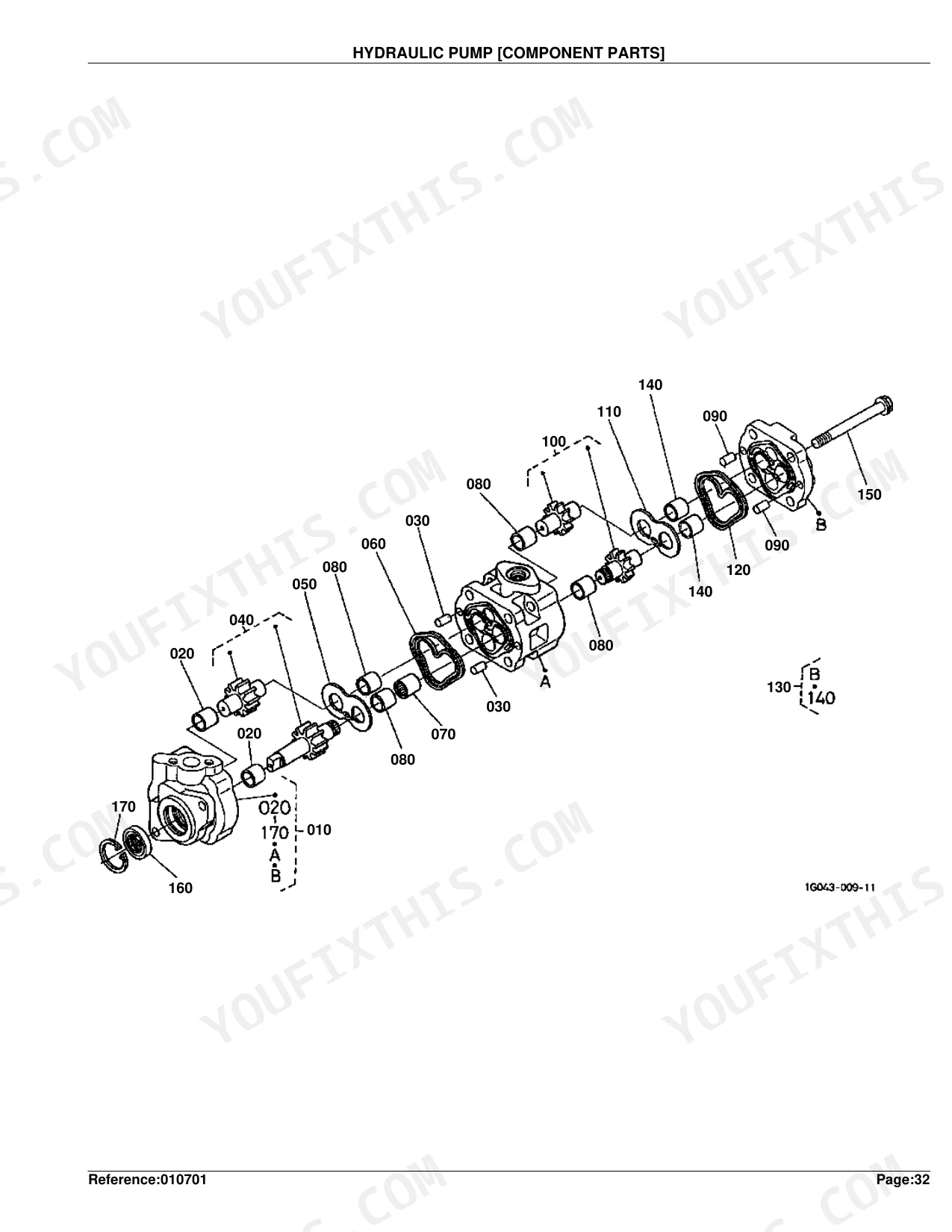
| Hydraulic Pump | 72-73 |
| Hydraulic Pump [Component Parts] | 74-75 |
| Upper Gasket Kit | 76-79 |
| Lower Gasket Kit | 80-81 |
| Alternator Kit | 82-83 |
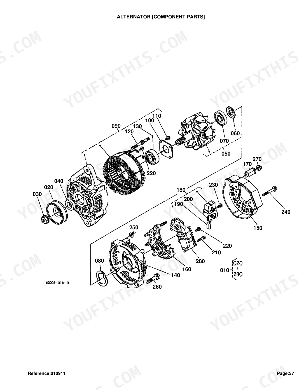
| Alternator [Component Parts] | 84-85 |
| Accelerator Lever | 86-87 |
| Fuel Tank | 88-90 |
| Fuel Pipe | 91-94 |
| Fuel Filter [Component Parts] | 95-96 |
| Fan | 97-98 |
| Water Pipe | 99-100 |
| Radiator [4WD] [Except[Au]] | 101-103 |
| Radiator [4WD] [Au] | 104-106 |
| Reserve Tank | 107-108 |
| Stop Solenoid | 109-111 |
| Starter | 112-113 |
| Starter [Component Parts] | 114-116 |
| Battery [Except[Au]] | 117-118 |
| Battery [Au] | 119-120 |
| Switch | 121-124 |
| Panel Board | 125-126 |
| Panel Board [Component Parts] | 127-128 |
| Head Light | 129-130 |
| Hazard Light | 131-133 |
| Tail Light | 134-135 |
| Electrical Wiring | 136-140 |
| Clutch Rod | 141-142 |
| Clutch Pedal | 143-144 |
| Clutch Housing [4WD] | 145-146 |
| Front Frame [4WD] | 147-148 |
| Center Frame | 149-150 |
| Transmission Case | 151-153 |
| Differential Gear Case | 154-155 |
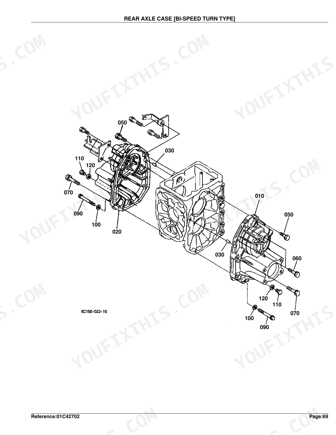
| Rear Axle Case [Bi-Speed Turn Type] | 156-157 |
| Clutch Shaft | 158-159 |
| Propeller Shaft | 160-161 |
| HST | 162-163 |
| HST [Component Parts] | 164-166 |
| Front Shaft | 167-168 |
| PTO Shaft | 169-170 |
| Mid PTO | 171-172 |
| Rear Differential | 173-174 |
| Front Wheel Propeller Shaft [4WD] | 175-176 |
| 2Nd Shaft | 177-178 |
| 3Rd Shaft | 179-180 |
| 4Th Shaft | 181-182 |
| Range Gear Shift Fork | 183-184 |
| PTO Gear Shift Fork | 185-186 |
| Differential Lock Shift Fork | 187-188 |
| Rear Axle | 189-190 |
| Brake | 191-192 |
| Brake Rod 1 | 193-194 |
| Parking Brake Lever [Except[Au]] | 195-196 |
| Parking Brake Lever [Au] | 197-198 |
| Speed Set Lever | 199-200 |
| Neutral Holder Link | 201-202 |
| Speed Control Pedal | 203-204 |
| Range Gear Shift Lever | 205-206 |
| Front Wheel Drive Lever [4WD] | 207-208 |
| PTO Gear Shift Lever | 209-211 |
| Bi-Speed Turn Lever [Bi-Speed Turn Type] | 212-214 |
| Hydraulic Control Lever | 215-216 |
| Brake Pedal | 217-218 |
| Differential Lock Pedal | 219-220 |
| Front Axle Case [4WD] [Bi-Speed Turn Type] | 221-230 |
| Front Differential [4WD] [Bi-Speed Turn Type] | 223-224 |
| Differential Gear Shaft [4WD] | 225-226 |
| Bevel Gear Case [4WD] | 227-228 |
| Front Axle [4WD] | 231-232 |
| Bi-Speed Turn Clutch [Bi-Speed Turn Type] | 233-234 |
| Front Drive Shaft [4WD] [Bi-Speed Turn Type] | 235-236 |
| Bi-Speed Turn Gear Case [Bi-Speed Turn Type] | 237-238 |
| Bi-Speed Turn Case [Bi-Speed Turn Type] | 239-240 |
| Bi-Speed Turn Shift Lever [Bi-Speed Turn Type] | 241-242 |
| Knuckle Arm [4WD] | 243-244 |
| Drag Link | 245-246 |
| Tie Rod [4WD] | 247-248 |
| Steering Handle | 249-250 |
| Steering Post | 251-252 |
| Hydraulic Pump(Ps) | 253-254 |
| Hydraulic Pump(Ps) [Component Parts] | 255-256 |
| Hydraulic Oil Line(Suction) | 257-259 |
| Hydraulic Oil Line(Delivery) | 260-261 |
| Hydraulic Oil Line(Steering) | 262-264 |
| Hydraulic Oil Line (HST) | 265-266 |
| Hydraulic Oil Line (Oil Cooler) | 267-269 |
| Hydraulic Oil Line (F/M) | 270-271 |
| Hydraulic Cylinder | 272-274 |
| Hydraulic Piston/Lift Arm | 275-276 |
| Feed Back Lever | 277-278 |
| Control Valve | 279-280 |
| Control Valve [Component Parts] | 281-282 |
| 3-Point Linkage 2(Lift Rod) | 283-284 |
| Lower Link | 285-286 |
| 3-Point Linkage 1(Lower Link) | 287-288 |
| Check Chain | 289-290 |
| Drawbar | 291-292 |
| Hitch | 293-294 |
| PTO Protector [Except[Au]] | 295-296 |
| PTO Protector [Au] | 297-298 |
| Front Grille [Except[Au]] | 299-300 |
| Front Grille [Au] | 301-302 |
| Bonnet | 303-304 |
| Panel Cover | 305-306 |
| Side Cover [Except[Au]] | 307-308 |
| Side Cover [Au] | 309-310 |
| Shutter Plate | 311-313 |
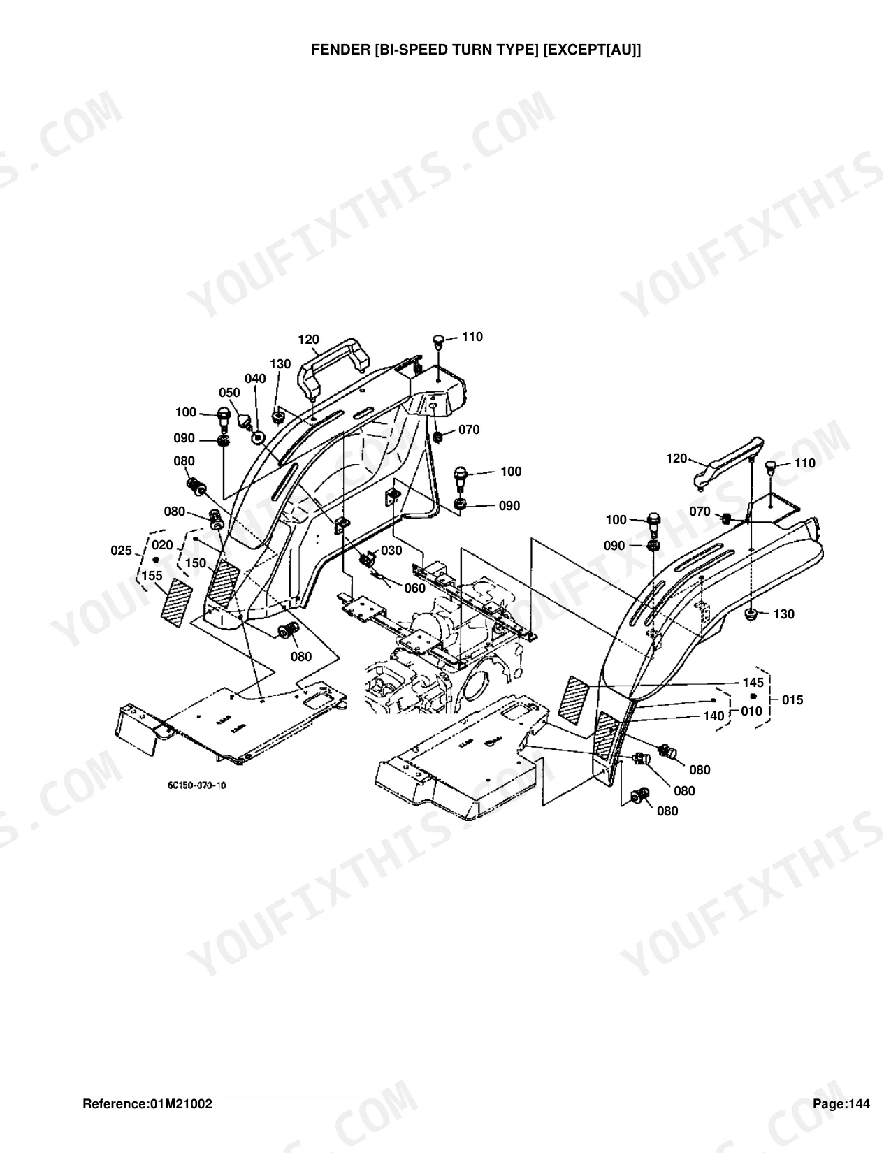
| Fender [Bi-Speed Turn Type] [Except[Au]] | 314-315 |
| Fender [Bi-Speed Turn Type] [Au] | 316-317 |
| Fender Stay [Bi-Speed Turn Type] | 318-319 |
| Floor Seat | 320-321 |
| Seat Support | 322-324 |
| Step | 325-326 |
| ROPS Kit (Rigid Type) | 327-328 |
| Smv Emblem | 329-330 |
| Front Wheel (7-12) [Except[Au]] | 331-332 |
| Front Wheel (21X8.00-10) [Except[Au]] | 333-334 |
| Front Wheel (23X8.50-12) [Except[Au]] | 335-338 |
| Front Wheel (6.00-12) [Au] | 339-340 |
| Front Wheel (24X8.50-12) [Au] | 341-342 |
| Rear Wheel (11.2-16) [Except[Au]] | 343-344 |
| Rear Wheel (31X15.5-15) [Except[Au]] | 345-346 |
| Rear Wheel (33X12.5-15) [Except[Au]] | 347-348 |
| Rear Wheel (12-16.5) [Except[Au]] | 349-350 |
| Rear Wheel (9.5-18) [Au] | 351-352 |
| Rear Wheel (315/75D-15) [Au] | 353-354 |
| Label [4WD] [Bi-Speed Turn Type] [A] | 355-356 |
| Label [4WD] [Bi-Speed Turn Type] [Ca] | 357-358 |
| Label [4WD] [Bi-Speed Turn Type] [Au] | 359-360 |
| Accessories and Service Parts | 361-362 |
| Warking Light Kit [Option] | 363-364 |
| Power Steering Hose Kit [Option] | 365-366 |
| ROPS Kit (Foldable Type) [Option] | 367-368 |
Quick Reference Specifications
| Specification | Value | Page |
|---|---|---|
| FUSE AUTO current rating | 5A | p. 138 |
| FUSE current rating | 30A | p. 138 |
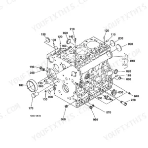
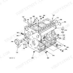
| CRANKCASE (COMP.CRANKCASE) Weight | 32 kgf | p. 8 |
| CYLINDER HEAD (COMP.CYLINDER HEAD) Weight | 9.2 kgf | p. 12 |
| OIL FILTER (ASSY CARTRIDGE OIL) Weight | 0.35 kgf | p. 19 |
| PISTON AND CRANKSHAFT (COMP.CRANKSHAFT) Weight | 9.58 kgf | p. 28 |
| FLYWHEEL (COMP.FLYWHEEL) Weight | 17.2 kgf | p. 30 |
| FUEL PUMP(MECHANICAL) (ASSY PUMP FUEL) Weight | 0.13 kgf | p. 51 |
| DYNAMO AND PULLEY (ASSY DYNAMO) Weight | 1.33 kgf | p. 54 |
| WATER PUMP (ASSY PUMP WATER) Weight | 0.8 kgf | p. 60 |
| HYDRAULIC PUMP (ASSY PUMP HYDRAULIC) Weight | 2.22 kgf | p. 73 |
| RADIATOR [4WD] [EXCEPT[AU]] (ASSY RADIATOR) Weight | 4 kgf | p. 103 |
Kubota B2410HSDB Common Problems This Manual Covers
Kubota B2410HSDB won't start or loses electrical power, need correct fuse part numbers p. 136
Open the electrical section starting at page 136. The fuse block carries 5A, 10A, and 20A auto fuses plus a 30A maxi fuse; part numbers for each rating appear on pages 138 and 140. Cross-reference the circuit position in the parts list to pinpoint which fuse covers the failed circuit before ordering.
Manual Section: Electrical WiringEngine won't shut off or refuses to start, need stop solenoid assembly part number p. 109
Review the stop solenoid exploded view on page 109. Identify all sub-components: solenoid body, mounting hardware, and wiring pigtail, each listed by part number. Check the electrical parts list on page 136 to confirm which fuse circuit (5A or 10A) protects the solenoid so you can order the correct connector and fuse alongside the assembly.
Manual Section: Stop SolenoidCharging voltage reads low, need correct alternator kit and voltage regulator part numbers p. 82
Refer to page 82 for the alternator kit parts list covering the complete assembly (1.33 kgf). Internal components, including voltage regulator, brushes, and bearings, are diagrammed on page 84. Verify your serial number range before ordering; kit contents vary by production year and market region.
Manual Section: Alternator KitForward/reverse pedal stiff or won't return to neutral, need HST linkage part numbers p. 203
Check the speed control pedal diagram on page 203 for pivot pin and return spring part numbers. Cross-reference the neutral holder link on page 201 for link rod and bracket hardware. For internal HST parts, page 164 diagrams components individually; note that the hydraulic pump (2.22 kgf, page 73) is ordered separately from the external linkage.
Manual Section: Speed Control PedalBattery fails repeatedly, need correct replacement battery and bracket hardware part numbers p. 117
Pull up the battery exploded view on page 117 for non-AU models (page 119 for AU). The bracket assembly weighs 2.25 kgf per the listing on page 118; confirm you are ordering the correct bracket, hold-down rod, and terminal hardware together. If the charging system is also suspect, cross-reference the alternator kit on page 82.
Manual Section: Battery [Except[Au]]Frequently Asked Questions
What are the replacement specifications for fuses?
Fuse replacement part numbers are listed in the ELECTRICAL WIRING section: 30A fuse (Part No. 1G111-65720), 5A fuse (Part No. 66426-80010), 10A fuse (Part No. 48100-55880), and 20A fuse (Part No. 36919-56650).
What are the replacement specifications for relays?
The relay is Part No. 68881-53540, listed as COMP.RELAY in the SWITCH section on page 122 and again in the ALTERNATOR KIT section on page 83. No electrical performance specs (voltage, current) are provided in this parts book.
How will I receive this Kubota B2410HSDB Parts Catalog?
Instant PDF download. The full 368-page searchable Parts Catalog is available immediately after payment. Open it on your laptop, tablet, or phone right in the shop.
Is this Kubota B2410HSDB Parts Catalog printable?
Yes. The PDF has no DRM restrictions. Print any page or section you need for your shop. Works with any standard printer.
Can I find hydraulic circuit diagrams in this Kubota B2410HSDB manual?
This is a parts catalog, so it shows exploded parts diagrams rather than circuit schematics. It includes detailed exploded views of the hydraulic components — pump, control valve, cylinder, and oil lines — with OEM part numbers, not wiring-style circuit diagrams.
Document Quality
This document is a scanned PDF with an optical character recognition (OCR) layer, allowing you to easily search and copy the entire text content. The text throughout the document is consistently crisp and clear, ensuring it is easy to read on every page. Diagrams and illustrations are clear raster images, and all labels within them are distinct and readable, even when zoomed in. The pages are clean, free from scan artifacts, stains, or any significant marks, and there are no notable blank or irrelevant filler pages.


Reviews
There are no reviews yet.