
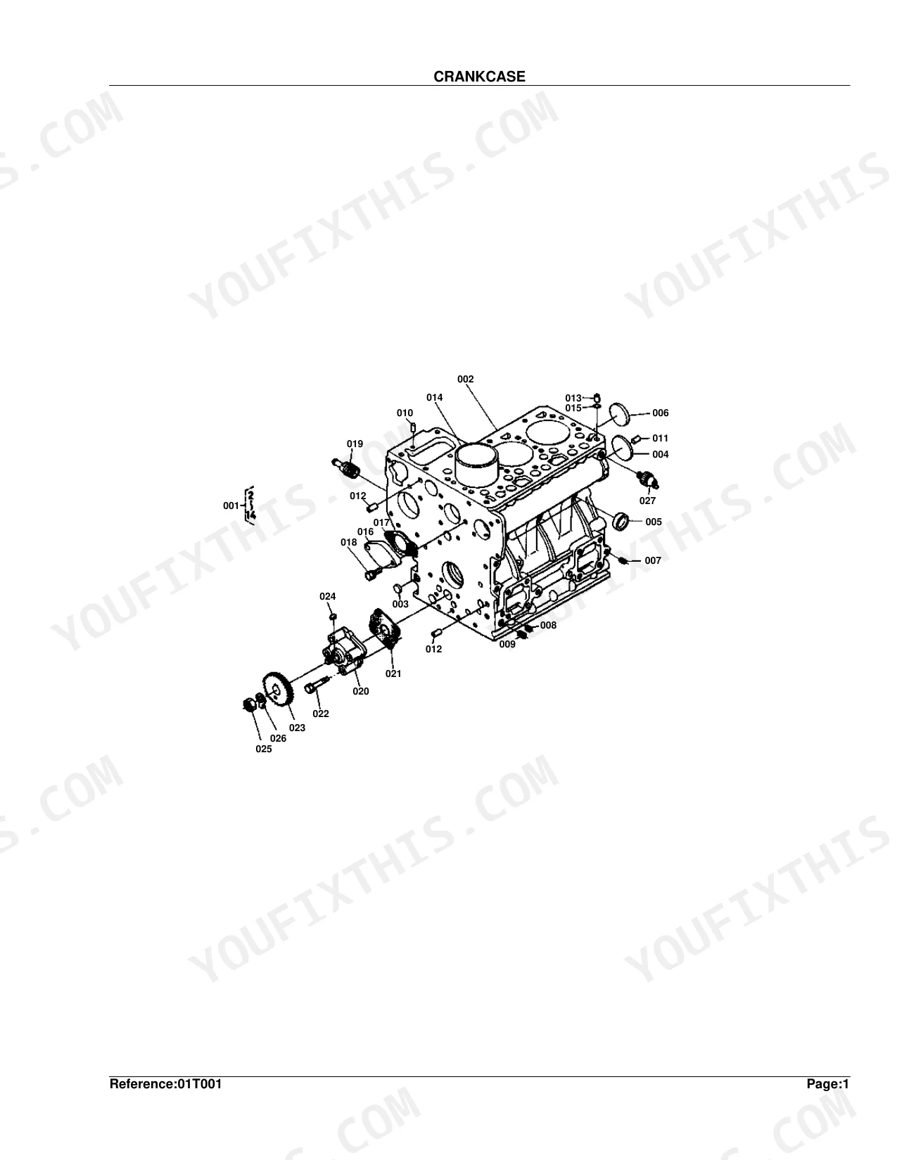
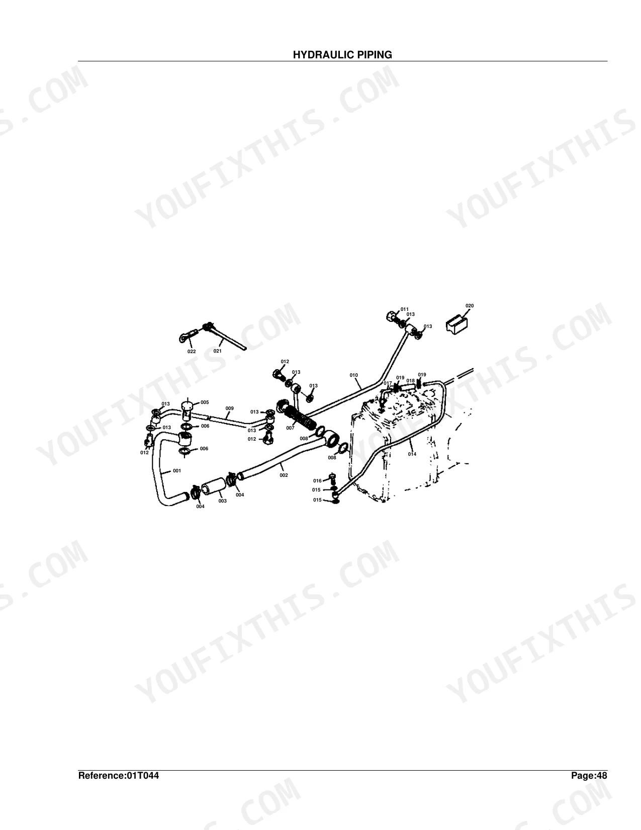
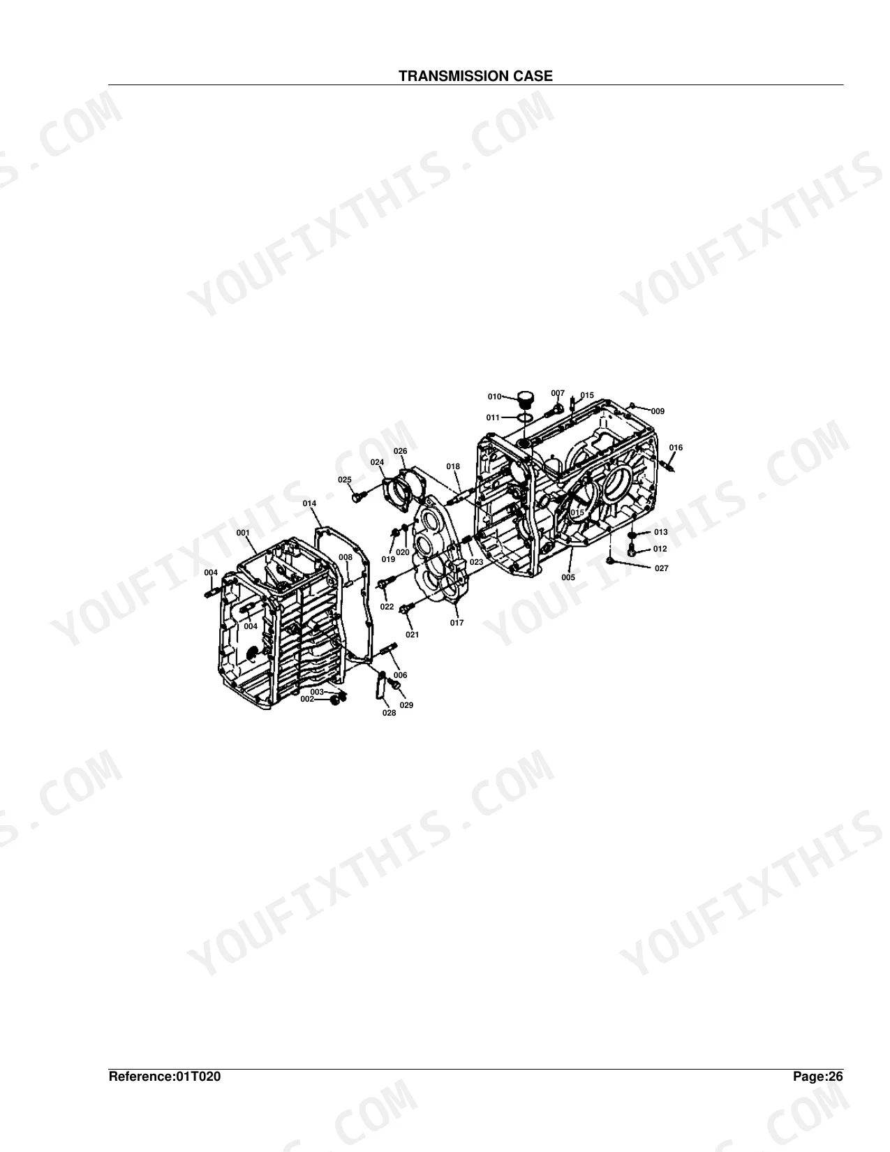
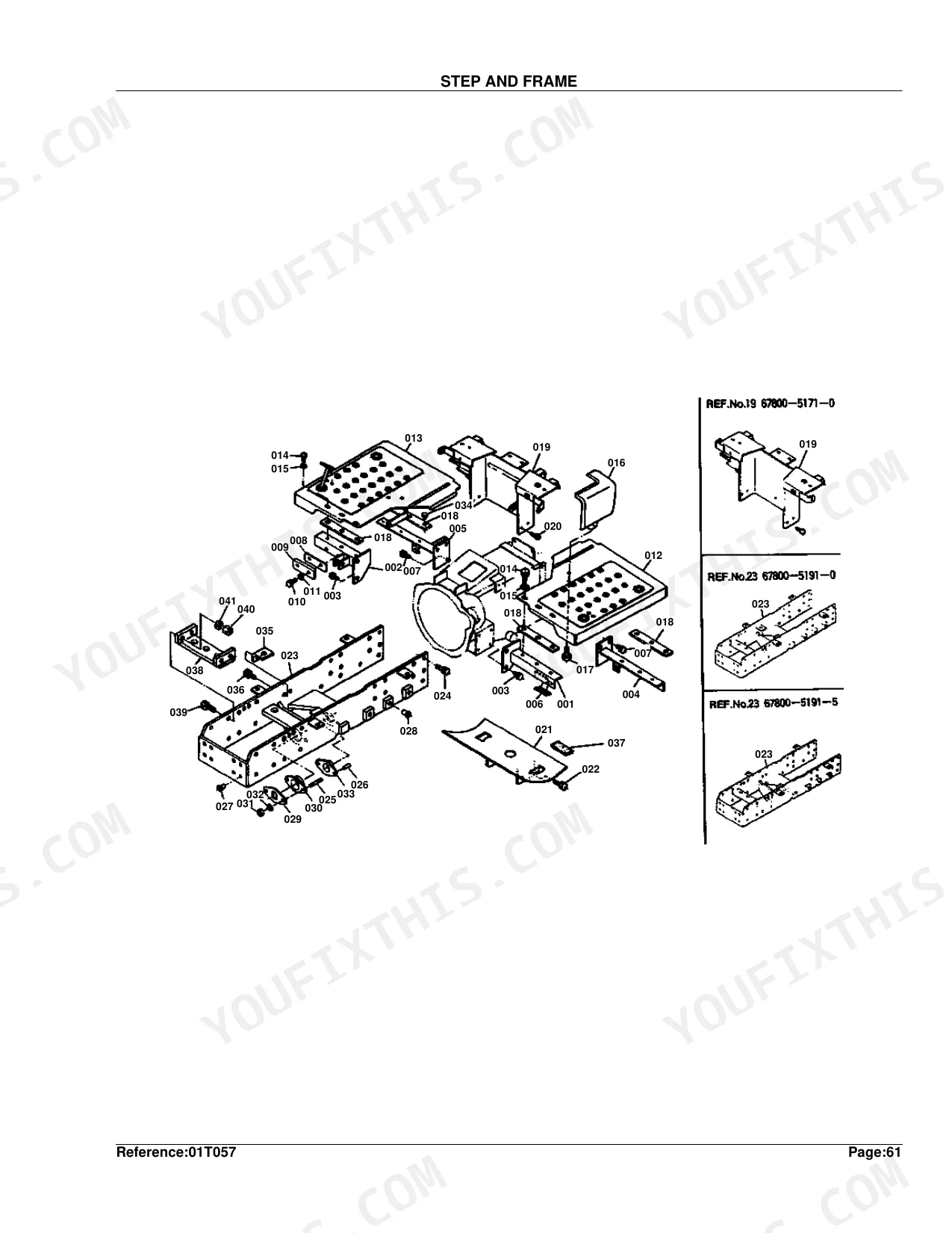
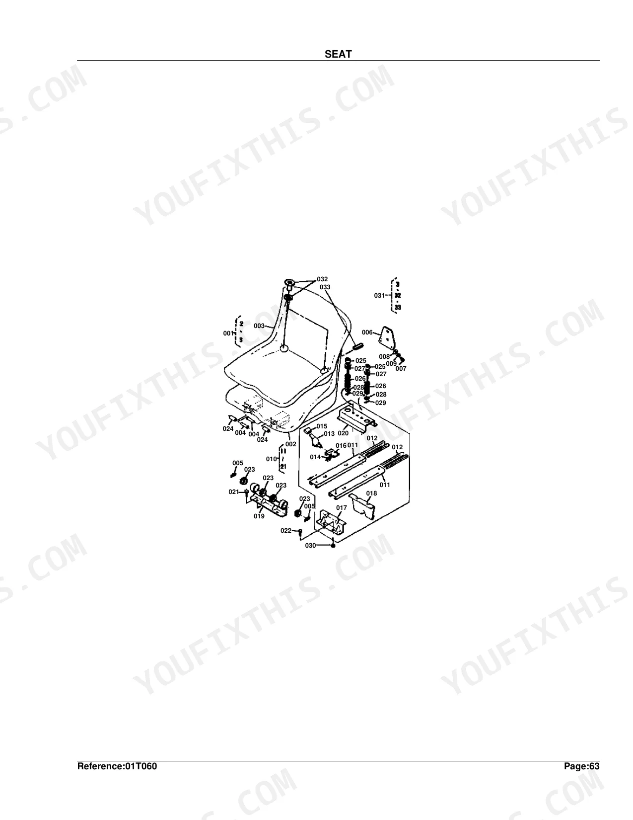
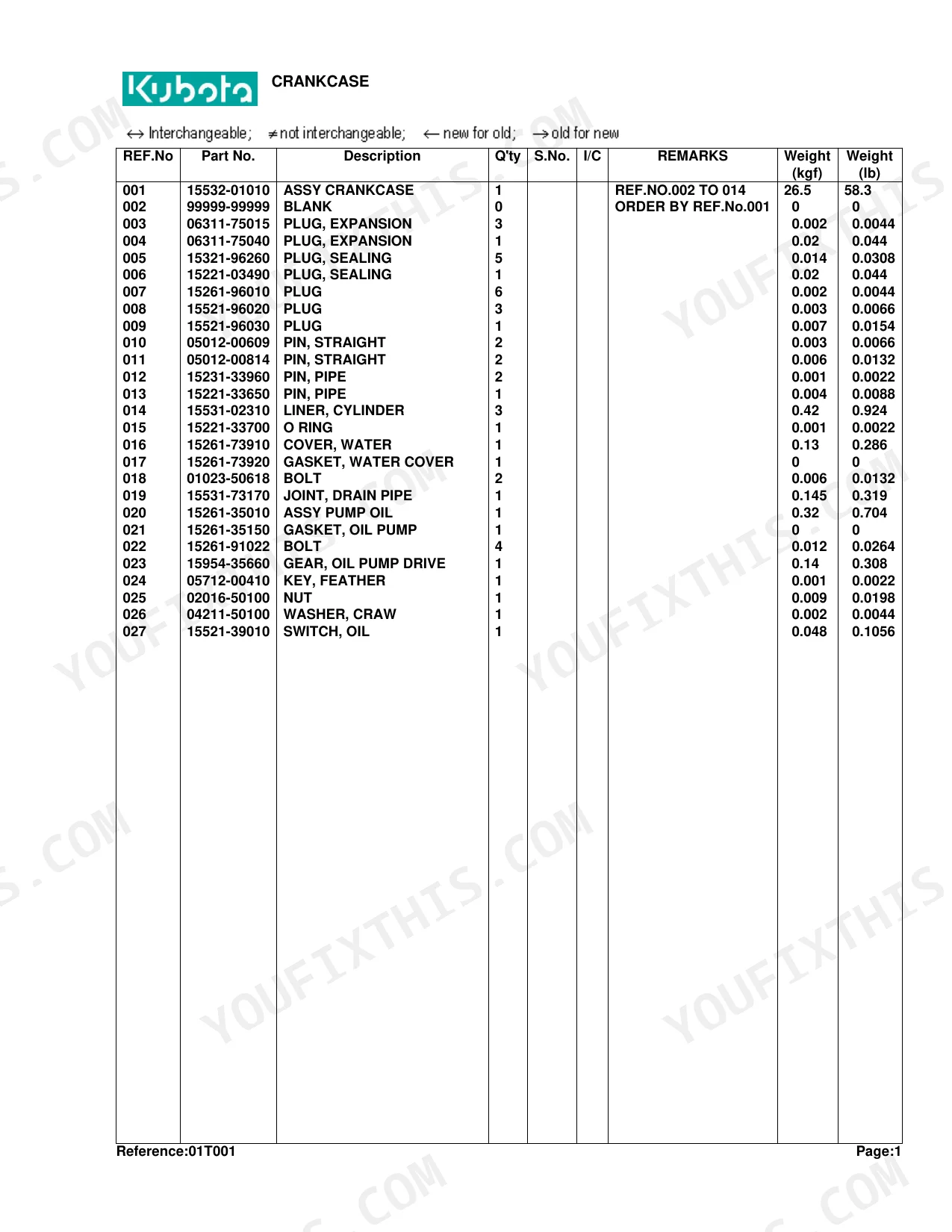
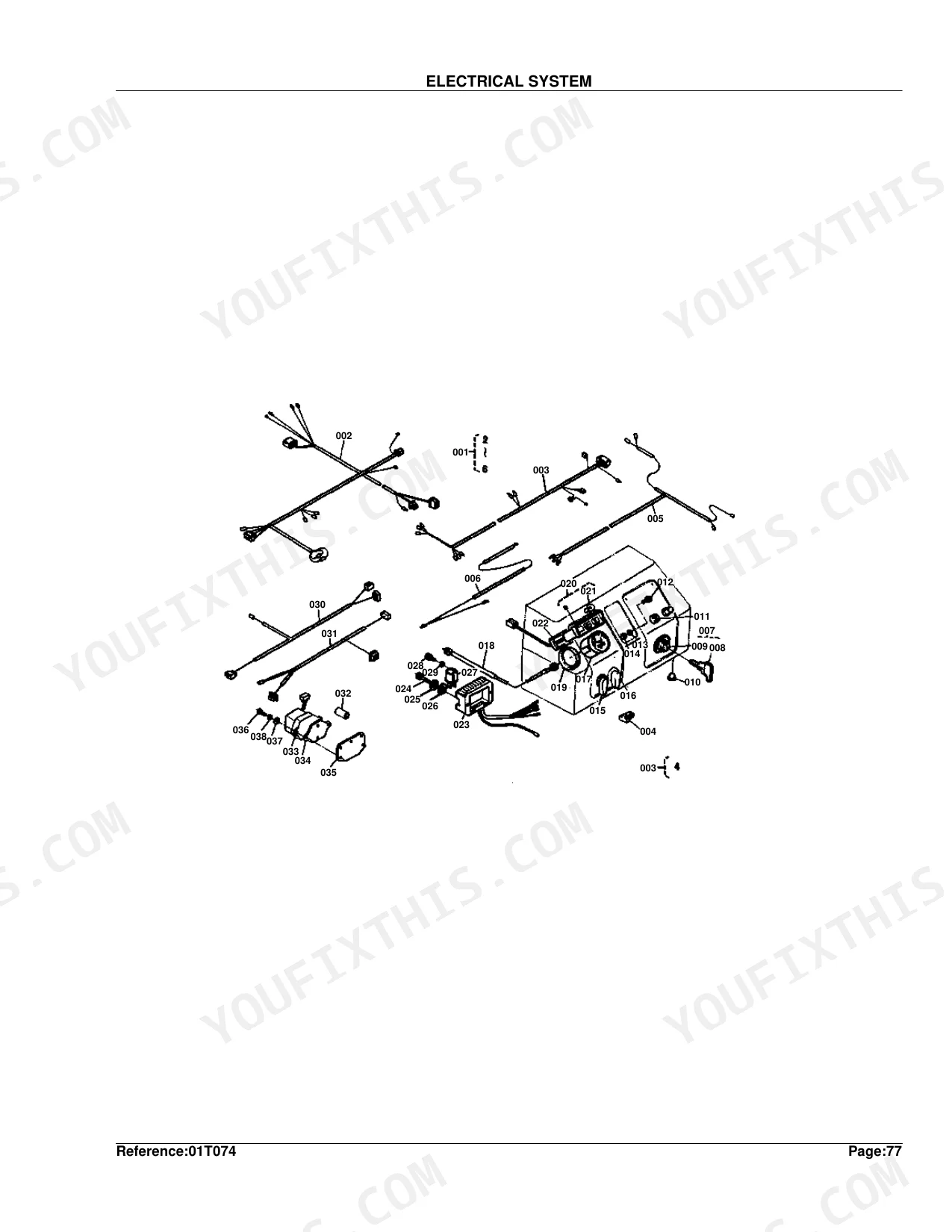
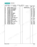
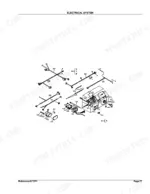
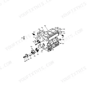
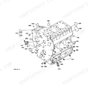
Need the factory part numbers for your Kubota B8200DP? At 202 pages, this catalog has one job: getting you to the right component on the first order. It runs 198 pages of exploded-view parts lists across engine internals, all seven drivetrain shafts, front and rear differentials, hydraulic control valve assemblies, chassis, electrical, and cab. The hydraulic parts diagrams trace fluid routing through the control valve and hydraulic block, so any line cross-references to its exact part number before you buy. Factory assembly weights run throughout: 26.5 kgf for the crankcase, 9 kgf for the cylinder head. That is genuine Kubota data, not a third-party guess. Skip the dead-end calls to the parts counter. Everything is bookmarked by system and keyword-searchable, so you can open it on a tablet, pull the right exploded view, and order once.
What's Inside This Kubota B8200DP Parts Manual
| System | Pages |
|---|---|
| Crankcase | 5-6 |
| Oil Pan | 7-8 |
| Cylinder Head | 9-10 |
| Gear Case | 11-12 |
| Main Bearing Case | 13-14 |
| Cylinder Head Cover | 15-16 |
| Inlet Manifold | 17-18 |
| Valve/Rocker Arm | 19-20 |
| Camshaft | 21-22 |
| Engine Stop Lever | 23-24 |
| Gear Pump | 25-26 |
| Piston/Crankshaft | 27-28 |
| Flywheel | 29-30 |
| Nozzle Holder | 31-32 |
| Speed Control Plate | 33-34 |
| Governor | 35-36 |
| Water Flange | 37-38 |
| Fuel Camshaft | 39-40 |
| Water Pump | 41-42 |
| Gear Pump [Section Parts] | 43-44 |
| Nozzle Holder [Section Parts] | 45-48 |
| Injection Pump [Section Parts] | 49-50 |
| Dynamo [Section Parts] | 51-52 |
| Starter [Section Parts] | 53-54 |
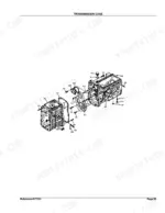
| Transmission Case | 55-56 |
| Cover | 57-58 |
| Axle Case | 59-60 |
| Clutch | 61-62 |
| 1 St Shaft and 2 Nd Shaft | 63-64 |
| 3 Rd Shaft | 65-66 |
| 4 Th Shaft and Reverse Shaft | 67-68 |
| Front Drive Shaft and 6 Th Shaft | 69-70 |
| 7th Shaft and PTO Shaft | 71-72 |
| Rear Differential | 73-74 |
| Rear Axle and Rear Wheel (8.3-24) [A] | 75-76 |
| Rear Axle and Rear Wheel (12.4-16) | 77-78 |
| Rear Wheel (13.6-16) [A] (T) | 79-80 |
| Main Speed Change | 81-82 |
| Speed Change Fork | 83-84 |
| Front Drive Fork | 85-86 |
| Rotary Speed Change Fork | 87-88 |
| Brake | 89-90 |
| Hitch | 91-92 |
| Case Cover and Lift Arm | 93-94 |
| Control Valve | 95-98 |
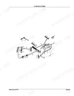
| Hydraulic Piping | 99-102 |
| Hydraulic Block | 103-106 |
| Steering | 107-110 |
| Speed Change Lever 1 | 111-112 |
| Speed Change Lever 2 | 113-114 |
| Clutch Pedal and Brake Pedal | 115-116 |
| Brake Rod | 117-118 |
| Release Lever | 119-120 |
| Name Plate | 121-122 |
| Clutch Housing | 123-124 |
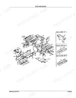
| Step and Frame | 125-126 |
| Fender | 127-128 |
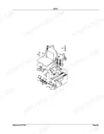
| Seat | 129-132 |
| Muffler and Muffler Pipet | 133-134 |
| Dustproof Net | 135-136 |
| Fuel Tank | 137-140 |
| Fuel Pipe | 141-142 |
| Decompress Wire and Engine Stop Wire | 143-144 |
| Hood and Panel | 145-148 |
| Skirt | 149-152 |
| Hood Bracket | 153-154 |
| Battery | 155-156 |
| Electrical System | 157-161 |
| Head Lamp and Flasher Lamp | 162-163 |
| Air Cleaner | 164-165 |
| Fuel Filter | 166-167 |
| Radiator | 168-169 |
| Dynamo and Starter | 170-171 |
| Front Axle Arm | 172-173 |
| Bevel Gear Case | 174-175 |
| Front Axle Case | 176-177 |
| Knuckle Arm | 178-179 |
| Front Differential | 180-181 |
| Bevel Gear | 182-183 |
| Drive Shaft | 184-185 |
| Front Wheel (6-12) | 186-187 |
| Front Wheel (24 X 8.50-12) (T) | 188-189 |
| Lift Rod | 190-191 |
| Check Chain and Bracket | 192-193 |
| Front Weight Bracket | 194-195 |
| Control Valve [Section Parts] | 196-201 |
| Accessories and Service Parts | 202-202 |
Quick Reference Specifications
| Specification | Value | Page |
|---|---|---|
| Weight | 0.35 kgf | p. 100 |
| ASSY CRANKCASE weight | 26.5 kgf | p. 6 |
| OIL PAN weight | 1.1 kgf | p. 8 |
| ASSY CYLINDER, HEAD weight | 9 kgf | p. 10 |
| ASSY CASE, GEAR weight | 0 kgf | p. 12 |
| ASSY CASE,MAIN BRG.1 weight | 0.8 kgf | p. 14 |
| COVER, CYLINDER HEAD weight | 0.66 kgf | p. 16 |
| MANIFOLD, INLET weight | 0.5 kgf | p. 18 |
| VALVE, INLET weight | 0.048 kgf | p. 20 |
| ASSY CAMSHAFT weight | 1.045 kgf | p. 22 |
| ASSY APPARATUS, IDLI weight | 0.023 kgf | p. 24 |
| ASSY GEAR PUMP weight | 1.59 kgf | p. 44 |
Kubota B8200DP Common Problems This Manual Covers
Kubota B8200DP tractor cranks but won't start, no-start or intermittent crank condition p. 157
Check the Electrical System diagram on page 157 to locate the fuse, relay, and key switch part numbers. Identify starter motor components in the Dynamo and Starter exploded view on page 170. Cross-reference the wiring harness parts on pages 157-161 to confirm you're ordering the correct connector and wire assembly for your serial number range before purchasing.
Manual Section: Electrical System Parts IdentificationFEL cylinder seals leaking hydraulic fluid, loader losing pressure or drooping under load p. 99
Turn to the Hydraulic Piping diagram on page 99 and the Control Valve Section Parts on page 196 to identify all seal kit and O-ring part numbers in the hydraulic circuit. Verify the gear pump assembly parts on page 43, noting the pump assembly weighs 1.59 kgf as a handling reference. Cross-reference seal part numbers against your machine's serial number range using the Model Compatibility Chart.
Manual Section: Hydraulic System Parts IdentificationPower steering or 3-point hitch loses function when front loader is connected to hydraulic circuit p. 103
Locate the Hydraulic Block exploded view on pages 103-106 to identify directional control valve, quick-connect fitting, and flow-control component part numbers. Check the Control Valve parts list on page 95 for the correct valve body and spool components. Compare part numbers on the Hydraulic Piping diagram on page 99 to verify all quick-connect and routing hardware matches your configuration.
Manual Section: Hydraulic System Parts IdentificationFront hub or knuckle area leaking, excessive play, or needs full disassembly for seal replacement p. 178
Open the Knuckle Arm parts diagram on page 178 to identify all seal, bearing, and snap-ring part numbers before teardown. Cross-reference with the Front Axle Case on page 176 and the Bevel Gear Case on page 174 to build a complete parts list for the hub area. Check the Front Axle Arm on page 172 to confirm you have the correct arm and spindle part numbers for your axle configuration.
Manual Section: Steering System Parts IdentificationStarter motor fails to engage or dynamo not charging, need replacement part numbers p. 53
Find the Starter Section Parts diagram on page 53 for starter motor component part numbers including the drive pinion and solenoid. For dynamo components, reference page 51. The combined Dynamo and Starter assembly view on page 170 shows both units in relation to each other, helping confirm you're ordering the correct housing and brush set for the B8200DP electrical spec.
Manual Section: Electrical System Parts Identification3-point hitch lift arm or lift rod worn, hitch won't hold position or raises unevenly p. 91
Reference the Hitch exploded view on page 91 and the Lift Rod parts list on page 190 to identify all pins, bushings, and lift arm part numbers. The Case Cover and Lift Arm diagram on page 93 shows the lift arm mounting hardware. Verify part numbers against the Model Compatibility Chart, as lift arm specs can differ by rear wheel configuration.
Manual Section: Hydraulic System Parts IdentificationFrequently Asked Questions
Where is the fuel filter on a Kubota B8200?
Page 166 shows the fuel filter assembly under the 'FUEL FILTER' section. The manual lists part 15231-43580 for the 'CUP, FILTER' and 15231-43560 for the 'ASSY ELEMENT'.
Where is the hydraulic filter on a Kubota B8200?
Part number 67800-37120, the 'FILTER, OIL', serves the hydraulic piping system. The illustration on page 99 shows its location within the hydraulic piping diagram.
What are the replacement specifications for fuses?
Page 158, in the ELECTRICAL SYSTEM section, lists a 'RING, FUSIBLE' as part number 67111-55190. Replacement specs like amperage are not given in this parts book, though.
What format is this Kubota B8200DP manual in?
Immediate download of the complete 202-page searchable Parts Catalog. Open it on any device, from the laptop at your desk to the phone in the field.
Can I print specific sections of this Kubota B8200DP Parts Catalog?
None at all. The PDF is DRM-free, so print whatever sections you need to take out to the shop. Standard letter or A4 paper works.
Are hydraulic system diagrams in this Kubota B8200DP Parts Catalog?
This is a parts catalog, so it shows exploded parts diagrams rather than circuit schematics. It includes detailed exploded views of the hydraulic components — pump, control valve, cylinder, and oil lines — with OEM part numbers, not wiring-style circuit diagrams.
Document Quality
This document is a scanned PDF with an OCR layer, meaning you can search and copy text throughout. The text quality is generally crisp and readable, though some characters show minor artifacts typical of scanned documents. Diagrams and illustrations are raster images, not vector, so they will pixelate if zoomed in too much, but labels are clear and readable at normal viewing sizes. Pages are mostly clean, with occasional minor scan artifacts or slight skewing that do not impact readability. There are no notable blank or filler pages.


Reviews
There are no reviews yet.