


Kubota built three crankcase sizes and two drivelines into this M-series lineup, and OEM #9Y011-10641 documents all of them: M4500, M5500, and M7500 in both 2WD and 4WD, A and AC. The hydraulic schematics trace the full circuit from pump through control valve, the wiring diagrams cover starting and charging, and exploded views walk through clutch, transmission, rear axle, and front axle teardowns. Servicing procedures run 91 pages, with 7 pages of troubleshooting, torque tables, clearance specs, and the maintenance checklist alongside. Fill the M4500 crankcase to 12 litres (13.0 U.S. qts.) and the fuel tank to 54 litres before first start; these are factory figures, not forum guesses. Bookmarks jump to any system, and the text is fully searchable, so finding a clearance spec takes seconds on whatever screen you have open.
What's Inside This Kubota M4500(A/AC), M5500(A/AC), M7500(A/AC) Manual
| System | Pages | Key Topics |
|---|---|---|
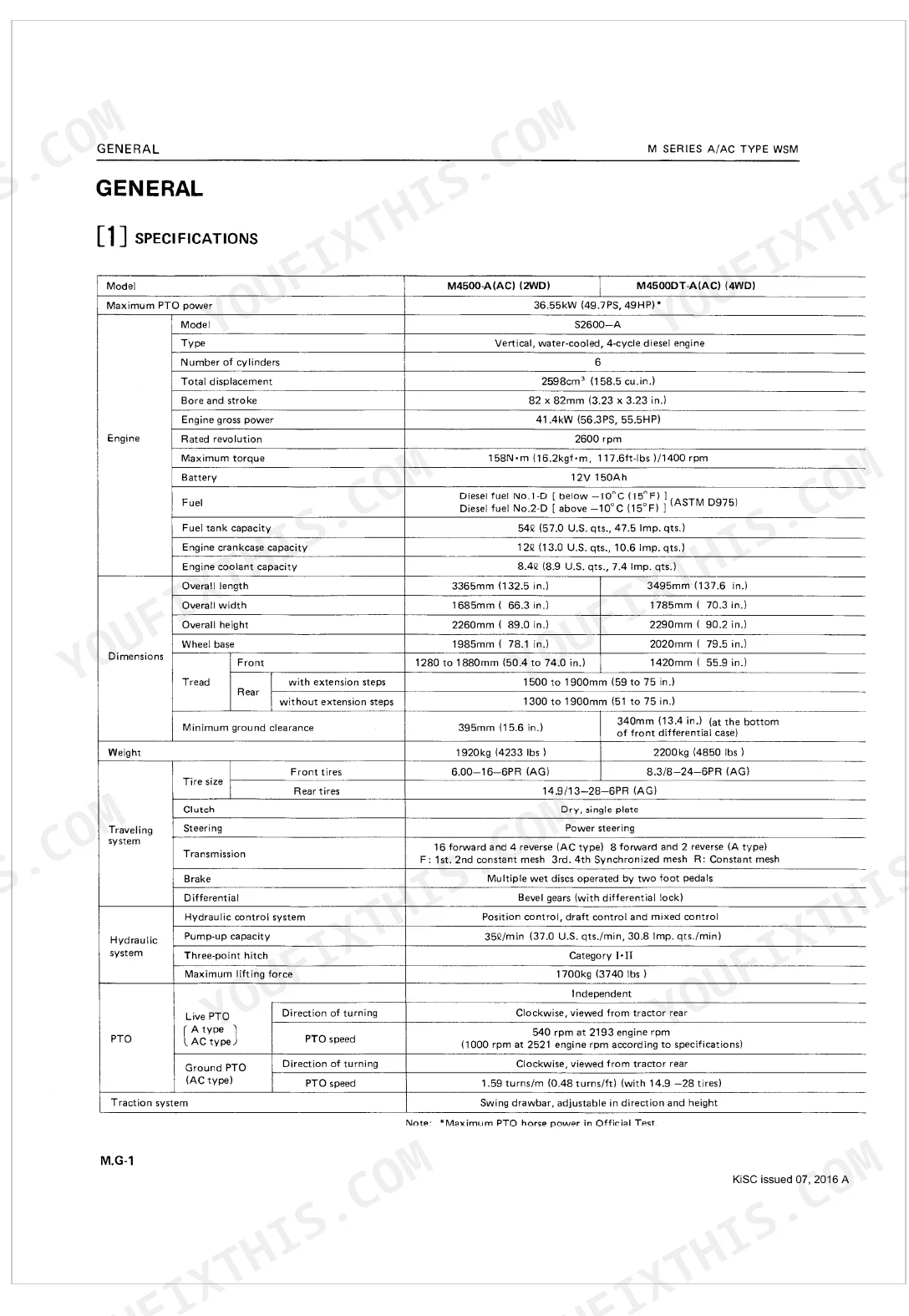
| General | 5-6 | Specifications (M4500-A, M4500Dt-A), M5500-A, M5500Dt-A, M7500-A, M7500Dt-A |
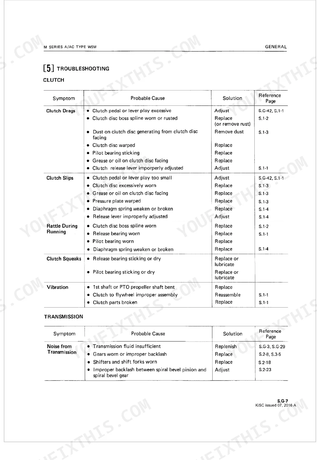
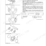
| Clutch | 7-9 | Clutch Overview, Dry Single-Plate Type, Dual Clutch (Traveling Clutch: Engage, Disengage), PTO Clutch Engage, PTO Clutch Disengage |
| Transmission | 10-19 | Main Gear Shift Section, Hi-Lo Gear Shift Section, Creep Gear Shift Section, PTO (Ground/Live) Section, PTO Gear Shift Section, Front Wheel Drive Section |
| Rear Axle | 20-23 | Rear Axle Overview, Differential Gear Assembly (During Straight Running, During Turning, Differential Lock), Planetary Gear System |
| Brakes | 24-26 | Brakes Overview, Features of Wet Type Disc Brakes (Reduced Wear of Disc, Stable Braking, Pedal Stroke Does Not Change Under Influence of Heat, Fading), Traveling Brakes |
| Front Axle | 27-28 | Front Axle System Overview, 2WD Type, 4WD Type |
| Steering | 29-33 | Steering Linkage, Steering Gear Box, Booster Unit |
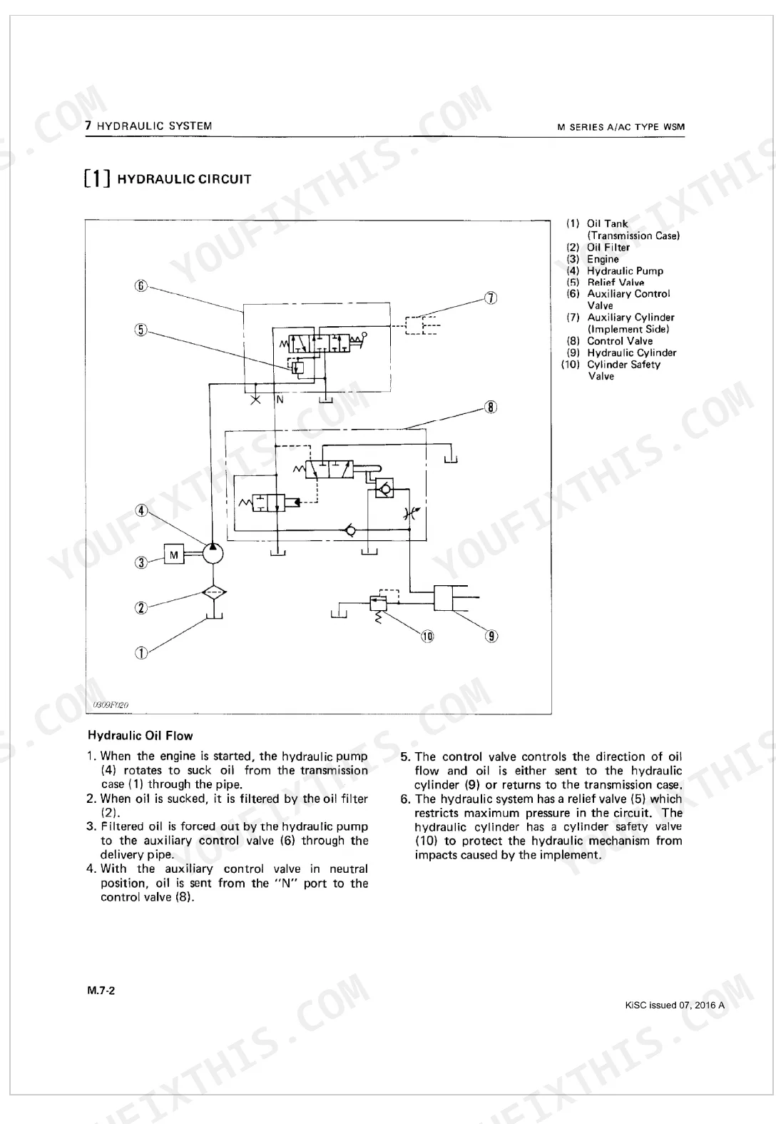
| Hydraulic System | 34-49 | Main Components and Functions, Hydraulic Circuit (Hydraulic Oil Flow), Hydraulic Pump For Lifting/Lowering System, Oil Filter, Control Valve (Neutral, Lift, Down) |
| Electrical System | 50-54 | Electrical Circuit, Wiring Diagram, Starting Circuit, Charging Circuit |
| Tires | 55-63 | Types of Tire, Adjustment of Tread, Weight, Tire Pressure, Tire Liquid Injection |
| Separation | 116-133 | Draining Coolant and Oil, Draining Oil from Front Axle, Separating Front Axle from Engine, Hood, Battery and Air Cleaner, Separating Front Axle, Separation of Front Axle Only |
| Clutch (Servicing) | 134-138 | Checking and Adjustment, Mounting on Clutch Disassembly/Reassembly Tool, Clutch Disc Thickness, Free Height of Diaphragm Spring |
| Transmission (Servicing) | 139-164 | Clutch Housing Disassembly and Assembly, Speed Change Cover, Shift Lever, Counter Shaft Cover and Clutch Release Bracket, Ball Bearing, Hi-Lo Fork Shaft, Reverse Shaft |
| Rear Axle (Servicing) | 165-174 | Differential Disassembly and Assembly, Differential Pinions and Differential Side Gears, Spiral Bevel Gear and Differential Case Cover, Set Collars, Differential Servicing |
| Brakes (Servicing) | 175-180 | Brakes Overview, Features of Wet Type Disc Brakes (Reduced Wear of Disc, Stable Braking, Pedal Stroke Does Not Change Under Influence of Heat, Fading), Traveling Brakes |
| Front Axle (Servicing) | 181-202 | 2WD Type Disassembly and Assembly, Front Wheel Hubs, Center Pin, 2WD Type Servicing, Clearance between Knuckle Shaft and Bushings, Toe-in, 4WD Type Disassembly and Assembly |
| Steering (Servicing) | 203-214 | Steering Assembly (Checking and Adjustment, Disassembly and Assembly), Booster Type Power Steering (Disassembly and Assembly, Servicing) |
| Hydraulic System (Servicing) | 215-235 | Control Linkage (Checking and Adjustment), Hydraulic Pump (Disassembly and Assembly, Servicing), Control Valve (Disassembly and Assembly) |
| Electrical System (Servicing) | 236-250 | Battery (Checking), Starting System (Checking, Disassembly and Assembly, Servicing), Charging Sytem (Checking and Adjustment |
| Back Cover | 251 | Editor Information (Address, Phone, Fax, E-mail), Publication Details |
Quick Reference Specifications
| Specification | Value | Page |
|---|---|---|
| M4500(A/AC) | ||
| Engine crankcase capacity | 12ℓ (13.0 U.S. qts., 10.6 Imp. qts.) | p. 5 |
| M5500(A/AC) | ||
| Engine crankcase capacity | 9.8ℓ (10.4 U.S. qts., 8.6 Imp. qts.) | p. 6 |
Kubota M4500(A/AC), M5500(A/AC), M7500(A/AC) Common Problems This Manual Covers
Kubota M4500 hydraulic implement does not rise, pump running but no noise at cylinder
Confirm the transmission fluid level first; the hydraulic system shares the sump, which holds 50.0ℓ (52.8 U.S. qts.) per page 67. Review the hydraulic schematic on page 35 to trace flow from pump through control valve. Check that the control lever fully engages the valve spool, and inspect the oil filter for clogging before pulling the pump.
Manual Section: Hydraulic System TroubleshootingClutch drags or won't fully disengage, difficult to shift gears without grinding
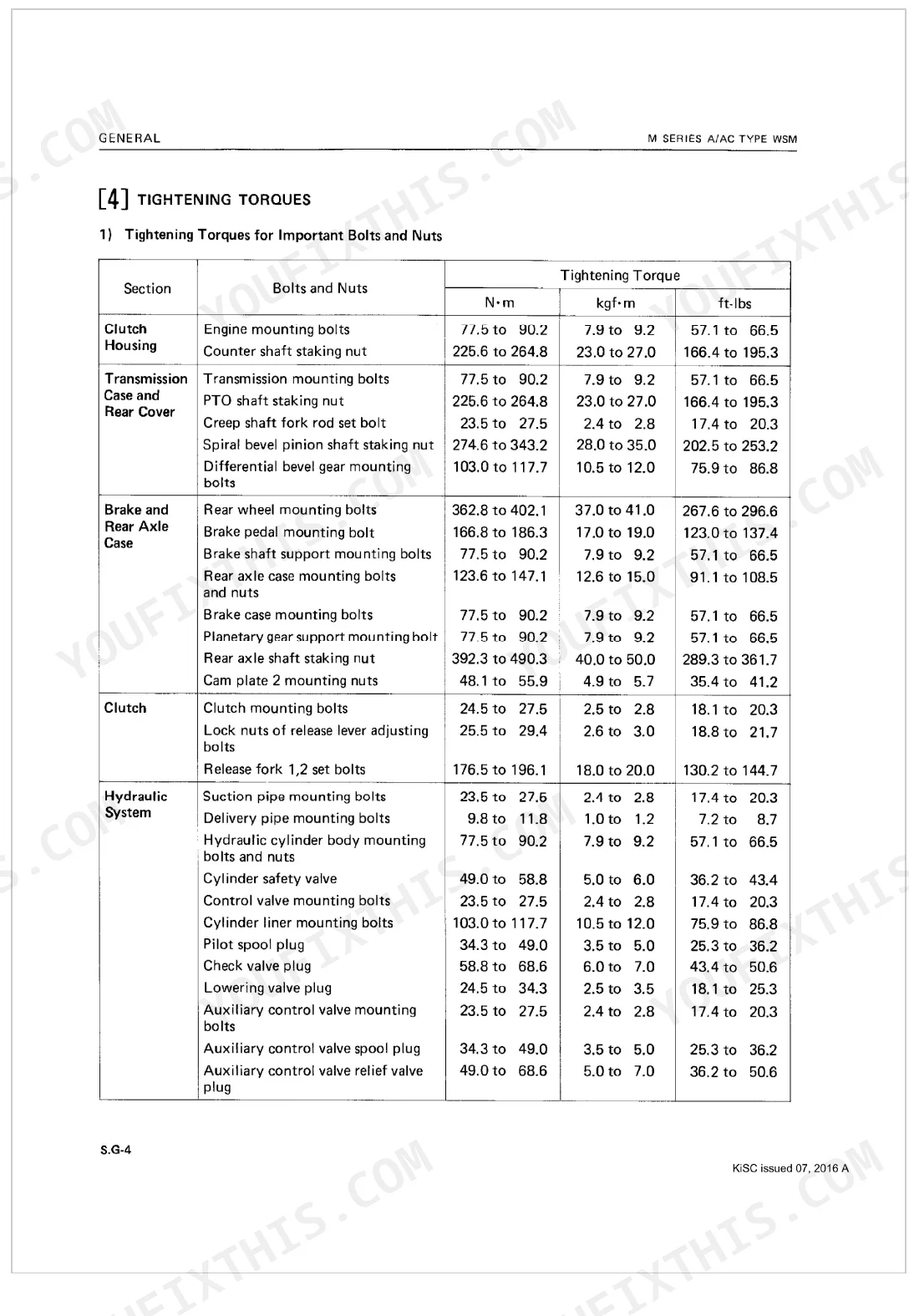
Measure clutch pedal free play and confirm disc thickness is within spec per the clutch servicing procedures on page 134. Torque the release fork set bolts to 176.5 to 196.1 N·m (18.0 to 20.0 kgf·m) per page 68. Inspect the diaphragm spring free height and replace the disc if it sits below the service limit.
Manual Section: Clutch TroubleshootingHard steering or excessive wheel effort at all speeds, no improvement after warmup
Top up the power steering fluid to its 2.0ℓ (2.1 U.S. qts.) capacity if low per page 67, and check the steering gear box is filled to 0.5ℓ (0.5 U.S. qts.). Inspect the booster unit for leaks or internal wear per the steering servicing section on page 203. With fluid level correct, trace the booster hydraulic circuit using the steering overview on page 29.
Manual Section: Steering TroubleshootingBraking force uneven side to side, tractor pulls hard left or right when stopping
Inspect both wet disc brake assemblies per the brakes servicing section on page 175. Adjust each pedal independently for equal travel before connecting the interlock. Torque the brake case mounting bolts to 77.5 to 90.2 N·m (7.9 to 9.2 kgf·m) per page 68. Disassemble the pulling side and check for scored discs or oil contamination if adjustment alone does not equalize force.
Manual Section: Brakes TroubleshootingFront wheels shimmy or vibrate at field speed on 4WD models, steering wheel shakes
Adjust toe-in per the front axle servicing section on page 181. Inspect the king pin staking nuts on 4WD models and torque to 245.2 to 294.2 N·m (25.0 to 30.0 kgf·m) per page 69. Confirm the front wheel mounting nuts sit at 259.9 to 304.0 N·m (26.5 to 31.0 kgf·m), and check the tie rod ends for excessive play.
Manual Section: Front Axle TroubleshootingGear slips out of mesh under load, transmission won't stay in selected gear
Cycle the shift lever through all ranges to test detent function; the transmission system diagram on page 12 identifies fork shaft locations. Check transmission fluid level against the 50.0ℓ (52.8 U.S. qts.) capacity on page 67. Inspect the hi-lo fork shaft and gear engagement teeth per the transmission servicing section on page 139; worn teeth are the most likely cause.
Manual Section: Transmission TroubleshootingFrequently Asked Questions
What are the recommended service intervals?
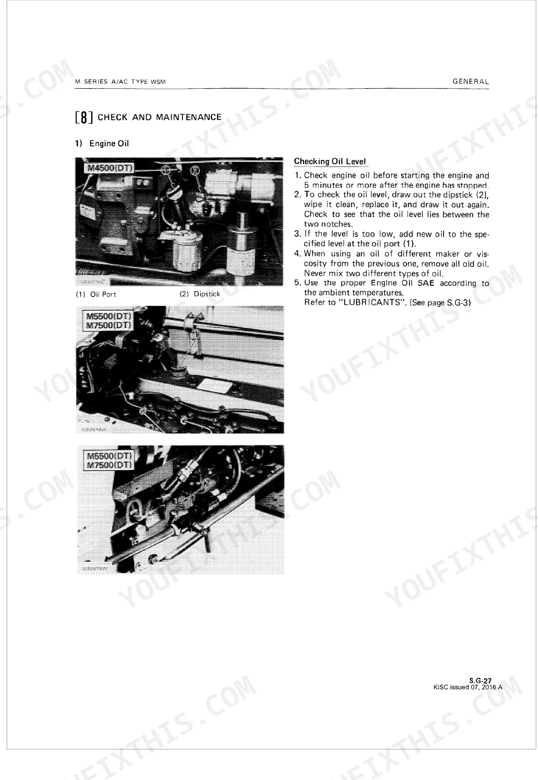
Intervals scale with hours. At 50 hours, grease the 3-point linkage group (3 spots) and the king pin (2 spots) [2WD], then check the clutch pedal free play. At 150 hours, change the engine oil and replace the oil filter cartridge, both [M4500(DT)].
What fluids and capacities does this machine require?
Each system has its own fill. The M4500(DT) crankcase takes 12.0 liters (12.7 U.S. qts.) of API Service CC or CD oil, the transmission holds 50.0 liters (52.8 U.S. qts.) of multi-grade fluid, and engine coolant comes to 8.4 liters (8.9 U.S. qts.).
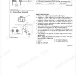
How to troubleshoot engine won't start?
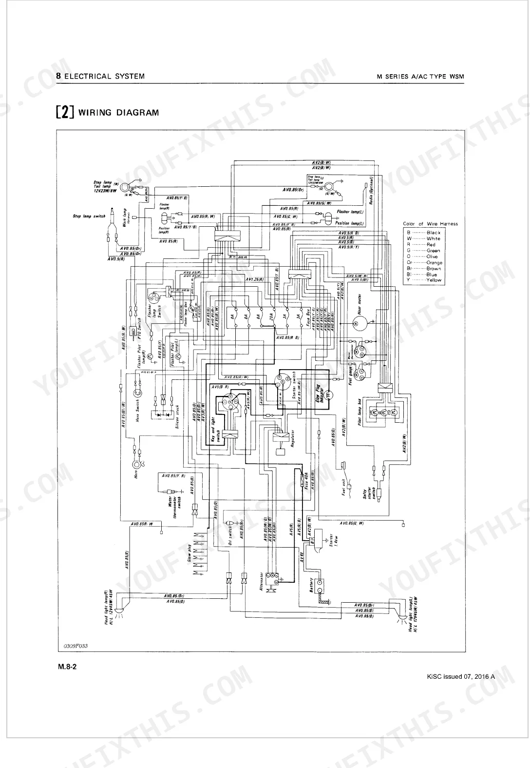
When the starter won't run, suspect a defective or discharged battery, or a blown fuse. Recharge or replace the battery, swap the fuse (M.8-2), or reconnect loose wire harnesses (M.8-2). A misadjusted or faulty safety switch, or a bad starter, also fits the symptom and needs adjustment or repair (S.8-3).
What are the hydraulic system specifications?
Pump-up capacity runs 35 liters/minute (37.0 U.S. qts./min), with a maximum lifting force of 1700 kg (3740 lbs). Relief valve pressure is set at 17.66 to 18.63 MPa (180 to 190 kgf/cm², 2560 to 2702 psi), and the M4500(DT) hydraulic cylinder liner I.D. measures 90.036 to 90.071 mm.
Is this Kubota M4500(A/AC), M5500(A/AC), M7500(A/AC) manual a digital download?
A 251-page Workshop Manual in searchable PDF, ready to download the moment checkout completes. Open it on a computer, tablet, or phone with no shipping wait.
Are there any print restrictions on this Kubota M4500(A/AC), M5500(A/AC)?
Absolutely. No DRM or copy protection. Print the whole manual or just the pages you need. Any home or office printer works.
Does this Kubota M4500(A/AC), M5500(A/AC), M7500(A/AC) manual include?
Full hydraulic system diagrams are included, covering circuits, valve locations, and hydraulic component specs for the Kubota M4500(A/AC), M5500(A/AC), M7500(A/AC).
Document Quality
This document is a high-quality scanned PDF with an excellent OCR layer, allowing you to search and copy all text. The text throughout is consistently crisp and clear, ensuring easy readability without any blurriness or fading. Diagrams and illustrations are raster images, but they are sharp enough for all labels and lines to be clearly discernible. The pages are clean, free from scan artifacts, stains, or skewed content, and there are no blank or filler pages present.


Reviews
There are no reviews yet.