


![Case CX210D TIER4 Repair Manual [Excavator]](https://youfixthis.com/wp-content/uploads/2012/02/Manual_Download-300x300.jpg)
Part of the Case Repair Manuals.
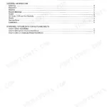
This is the complete Case factory service manual for the 585G, 586G, and 588G forklifts. It is organized into the standard Case service groups, General, Engines, Electrical, Steering, Power Train, Brakes, Hydraulics, and Mounted Equipment, and it includes the hydraulic and electrical schematic foldouts. Each group carries specifications, pressure checks, troubleshooting, and step-by-step removal, disassembly, inspection, assembly, and installation procedures, including the standard Carraro transmission, the drive axle and planetaries, and the forklift hydraulics, for all three models.
What's Inside This Case 585–588 Manual
| System | Pages | Key Topics |
|---|---|---|
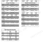
| General | Standard Torque Specifications, Fluids and Lubricants, Loctite Product Chart | |
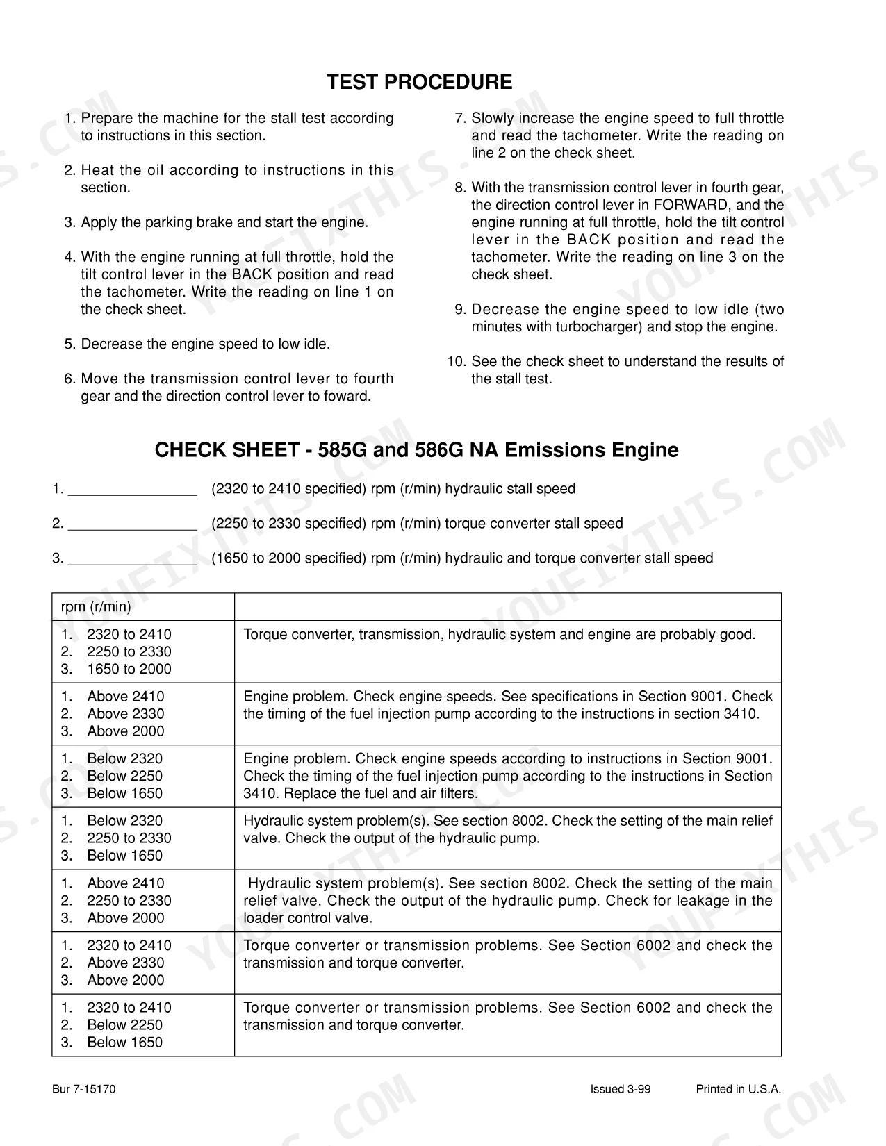
| Engines | Engine Removal and Installation, Stall Test | |
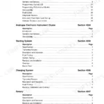
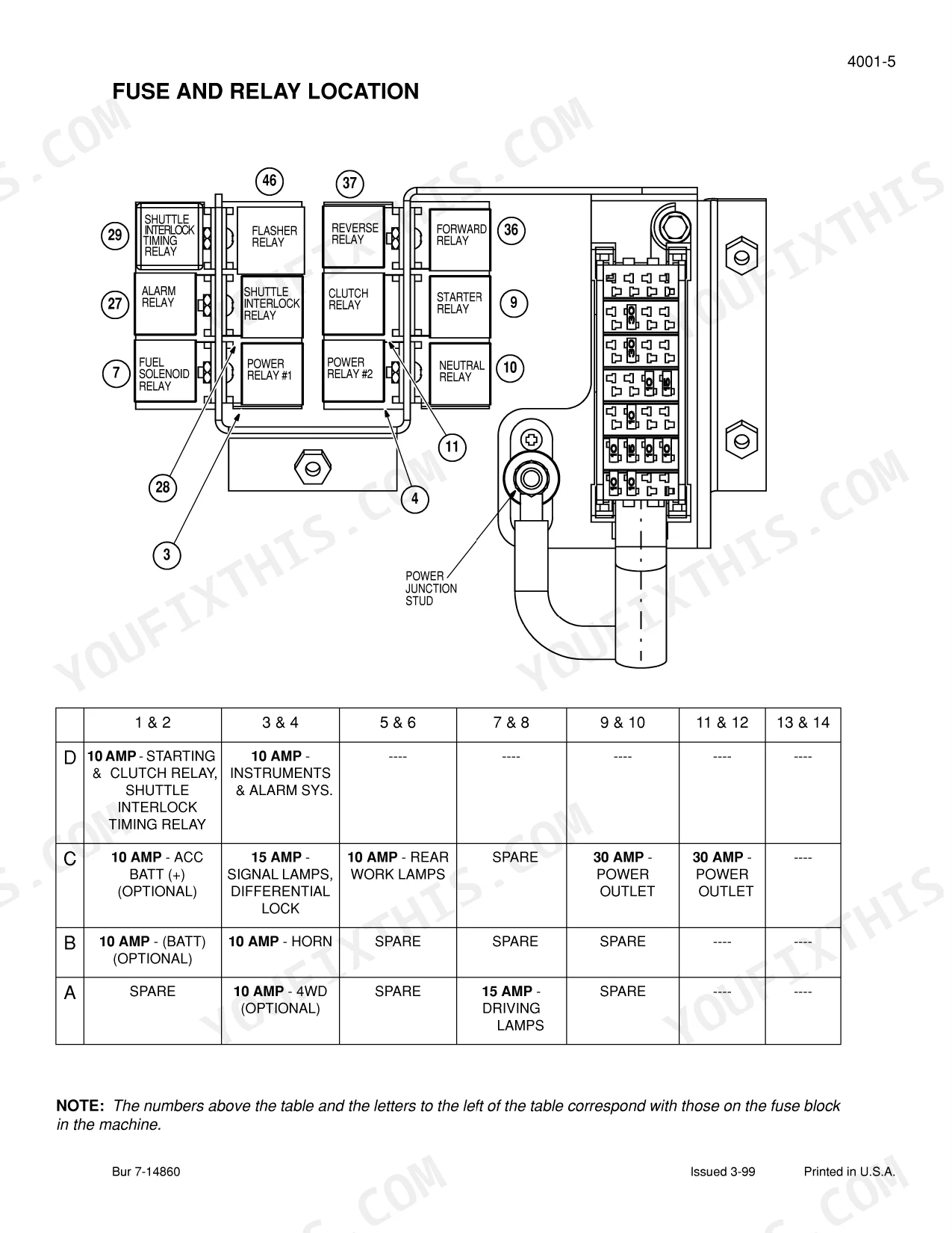
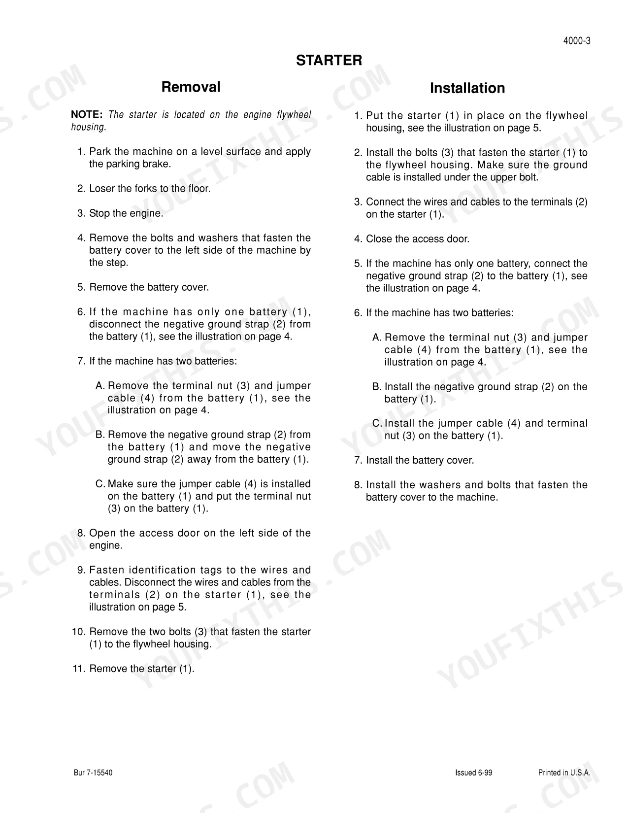
| Electrical | Removal and Installation of Electrical Components, Electrical Specifications and Troubleshooting, Batteries, Starter Motor - Denso, Instrument Cluster | |
| Steering | Removal and Installation of Steering Components, Steering Specifications, Pressure Checks and Troubleshooting, Steering Control Valve, Steering Cylinders | |
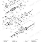
| Power Train | Removal and Installation of Power Train, Transmission Specifications, Pressure Checks and Troubleshooting - Forklift Early Production, Pressure Checks and Troubleshooting - Forklift Late Production, Wheels and Tires, Drive Axle and Planetaries, Standard (Carraro) Transmission | |
| Brakes | Removal and Installation of Brake Components, Master Cylinder | |
| Hydraulics | Removal and Installation of Hydraulic Components, Hydraulic Specifications, Troubleshooting, And Pressure Checks, Cleaning the Hydraulic System | |
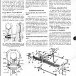
| Mounted Equipment | Pedals and Levers, ROPS Canopy, Seat and Seat Belts, Forklift Mast | |
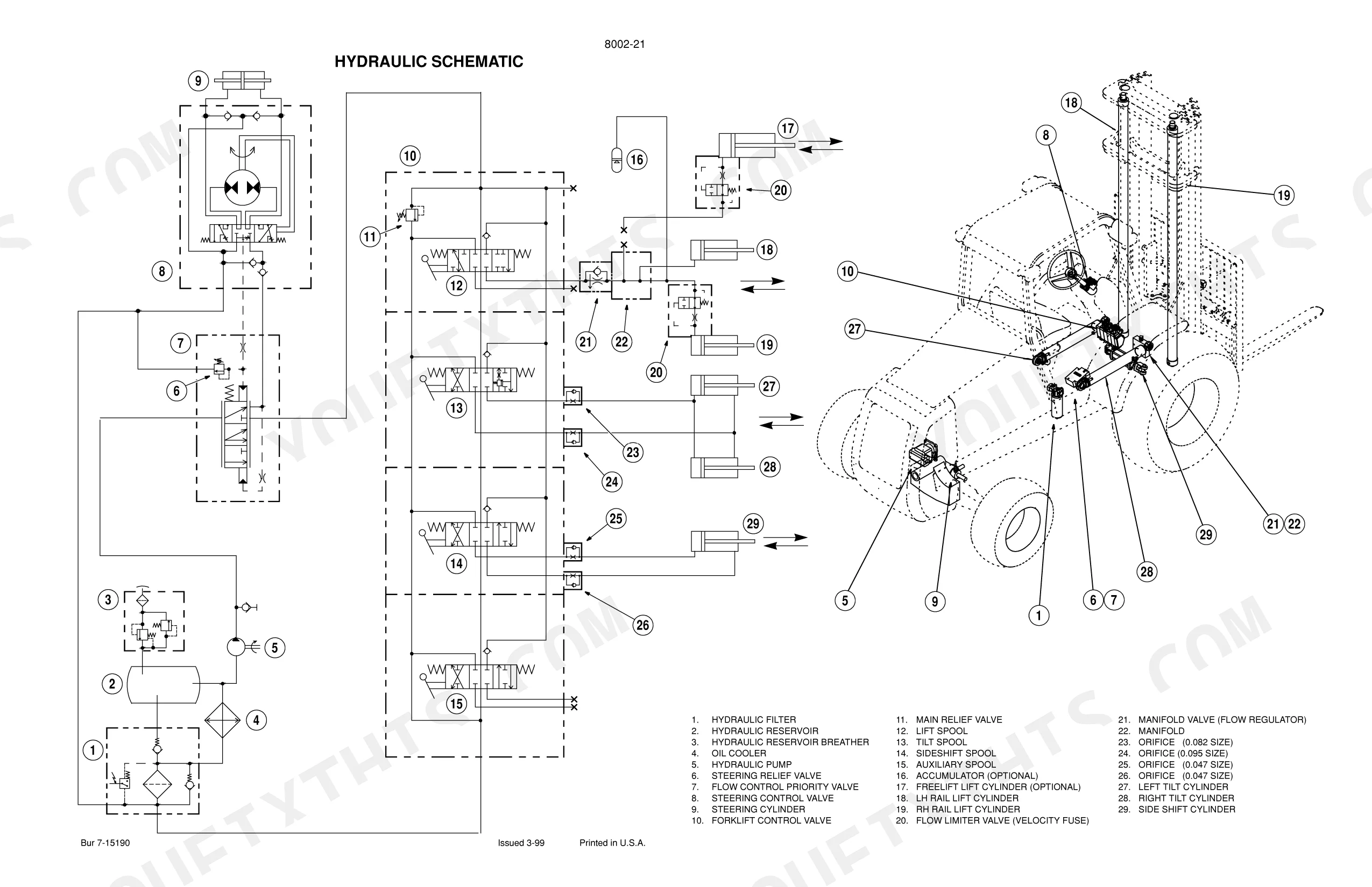
| Schematic Foldouts | Hydraulic Pump, Steering Control Valve, Forklift Control Valve, Battery, Alternator, Fuses |
Quick Reference Specifications
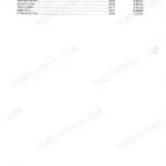
| Specification | Value | Page |
|---|---|---|
| Fitting for oil filter torque | 50 Nm (37 pound-feet) | p. 496 |
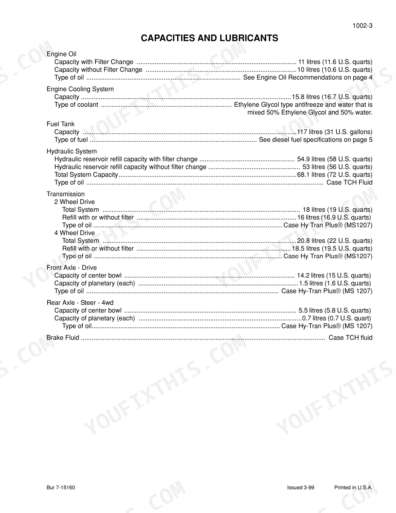
| Engine Oil Capacity (with filter change) | 11 litres | p. 13 |
| Hydraulic System Total Capacity | 68.1 litres | p. 13 |
| Transmission 4 Wheel Drive Total System | 20.8 litres | p. 13 |
| Diesel Fuel API gravity | 34 | p. 15 |
| Alternator Rated Output | 14 volts at 65 amperes | p. 129 |
| Steering Relief Valve Pressure Setting | 144 to 155 bar | p. 170 |
| Rear Wheel Bolts Torque | 156 to 203 Nm | p. 208 |
| Backlash for Ring Gear (Steering Axle - Four Wheel Drive) | 0.20 to 0.25 mm | p. 239 |
| Clutch Disc Clearance (Transmission) | 2.3 to 4.3 mm | p. 496 |
| Forklift Tilt Cylinder Torque | 365 to 460 Nm | p. 736 |
Case 585–588 Common Problems This Manual Covers
Case 585G Forklift constant fluid leakage at the open fitting of the steering cylinder
Inspect the steering cylinder piston packing for damage. Replace the seals and check the steering relief valve pressure setting on page 170 to verify it holds 144 to 155 bar. Reconnect the hose assembly securely and wipe away any residual hydraulic fluid before testing operation.
Manual Section: Steering p. 170E001 error code active with engine failure to lubricate correctly under normal operating conditions
Drain the system and replace the engine oil filter. Torque the fitting for the oil filter to 50 Nm (37 pound-feet) as shown on page 496. Fill the crankcase with exactly 11 litres of approved multi-viscosity engine oil. Check for leaks around the housing.
Manual Section: Standard (Carraro) Transmission p. 496Hydraulic arm drops when not fully engaged due to internal seal failure and erratic movement
Test the hydraulic circuit for pressure loss. Replace the worn seal set on the telescopic arm. Tighten the forklift tilt cylinder torque to 365 to 460 Nm as specified on page 736. Fill the hydraulic system to the 68.1 litres total capacity and bleed trapped air.
Manual Section: Hydraulics p. 736Battery drains quickly during operation and instrument cluster dims when operating heavy loads
Measure the alternator output across the battery terminals with the engine running. Verify the rated output reaches 14 volts at 65 amperes as detailed on page 129. Inspect the power relays and solenoids. Replace the alternator if output falls below specification during load testing.
Manual Section: Electrical p. 129Frequently Asked Questions
Which transmission is in my 585G, 586G, or 588G, and is it covered?
The Power Train group covers the standard Carraro transmission with full specifications, pressure checks, troubleshooting, and disassembly and assembly, along with the drive axle and planetaries. Run the transmission pressure checks first if the truck is slow to move or loses drive, since a pressure or control fault often mimics internal wear.
The forks lift slowly or the mast drifts down. Where do I look?
Go to the Hydraulics group and the schematic foldouts. Check the hydraulic pump, the forklift and steering control valves, and the relief pressures against spec before replacing parts. Mast drift is usually a control-valve or cylinder seal issue, both of which the removal, inspection, and assembly procedures cover.
What steering and axle service does this manual include?
The Steering group covers removal and installation of steering components, steering specifications and pressure checks, and the steering control valve, and the Power Train group covers the drive axle and planetaries with their disassembly and assembly. Confirm steering pressures before condemning the control valve or pump.
Does it cover the engine and electrical systems for all three models?
Yes. The Engines group covers engine removal and installation and the specifications, and the Electrical group covers removal and installation, electrical specifications, and troubleshooting for the 585G, 586G, and 588G. Deep internal engine rebuild is handled in the matching engine service manual that this book references.
Are the hydraulic and electrical schematics included?
Yes. The manual includes the hydraulic and electrical schematic foldouts, covering the hydraulic pump, steering control valve, and forklift control circuits, so you can trace hydraulic flow and wiring end to end instead of guessing.
Is this Case 585G, 586G, 588G, 585G Forklift, 586G Forklift, 588G Forklift?
This is a 786-page searchable PDF (273 MB) ready for immediate download. Works on any device, so pull it up on your phone while you're under the hood. No shipping, no waiting.
Can I print specific sections of this Case 585G, 586G, 588G, 585G Forklift?
Yes. The PDF has no DRM restrictions, so print any page or section you need for your shop. Works with any standard printer.