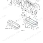
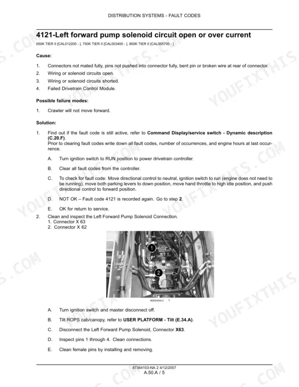


Part of the Case Repair Manuals.
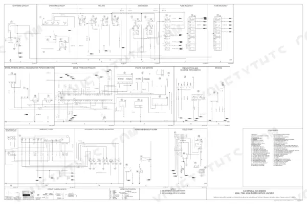
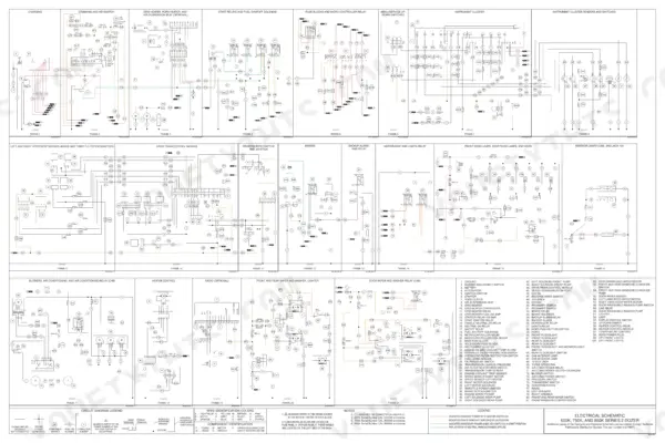
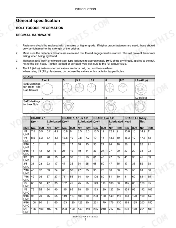
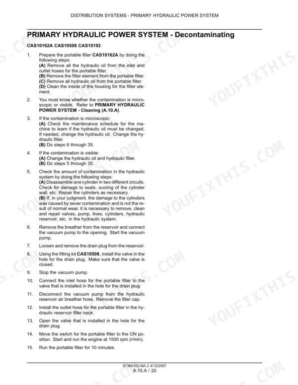
All 1,360 pages of this Case 650K, 750K, and 850K Tier II Repair Manual (OEM #87364103-NA) cover your dozer from primary hydraulics to final drive. Inside: electrical schematics for the battery, alternator, fuse blocks, and drive train controller; full hydrostatic circuit diagrams with complete fluid routing; a fault code library paired with troubleshooting procedures; and connector pinout tables for every control circuit. Dedicated chapters break down the hydrostatic transmission, service and parking brakes, track drive, blade positioning, and cab HVAC. The equipment pump flows 76.8 L/min at 207 bar at 2000 RPM. Torque the PTO shaft retainer to 68 Nm before buttoning up the pump assembly. No more chasing hydrostatic faults with a meter and a hunch. One-click download, jump to any chapter by bookmark, search any spec by keyword, and get back to wrenching.
What's Inside This Repair Manual
| System | Pages | Key Topics |
|---|---|---|
| Introduction | 6-19 | Basic Instructions, Hydraulic Contamination, Conversion Factors |
| Distribution Systems-A | 20-545 | Primary Hydraulic Power System, Secondary Hydraulic Power System, Electrical Power System, Lighting System, Fault Codes |
| Power Production-B | 546-655 | Engine, Fuel and Injection System, Air Intake System, Engine Coolant System, Lubrication System, Starting System |
| Power Train-C | 656-725 | Power Coupling Fixed Coupling, Transmission Hydrostatic |
| Travelling-D | 726-973 | Service Brake Hydraulic, Parking Brake Hydraulic, Wheels and Tracks Tracks, Final Drive |
| Body and Structure-E | 974-1201 | User Controls and Seat, User Platform, Environment Control Heating System, Environment Control Air-Conditioning System, Environment Control Heating |
| Tool Positioning-G | 1202-1315 | Lifting, Tilting, Swinging |
| Working Arm-H | 1316-1325 | Single Arm Tool Attachment Lift |
| Tools and Couplers-J | 1326-1356 | Digging Non-Articulated Digging Tools, Landscaping Dozer Blade |
| 5-6280 Schematics | 1357-1358 | Battery, Alternator, Ignition Switch, Starter, Fuse Blocks, Drive Train Controller |
| 6-78871 Schematics | 1359-1360 | Hydrostatic Pump Assembly, Hydrostatic Filter Assembly, Brake Solenoid Valve, Lift Cylinders, Tilt Cylinder, Oil Cooler Assembly |
Quick Reference Specifications
| Specification | Value | Page |
|---|---|---|
| All Models | ||
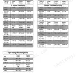
| Alternator pulley nut torque | 60 - 70 Nm (44 - 52 lb ft) | p. 325 |
| Non PTO pump cover bolts torque | 66 - 80 Nm (49 - 59 lb ft) | p. 30 |
| PTO shaft retainer torque | 68 Nm (50 lb ft) | p. 30 |
| Proximity switch clearance | 1 - 3 mm (0.040 - 0.118 in) | p. 755 |
| Control valve brake solenoid coil resistance | 9 to 10 ohms at 25 °C (77 °F) | p. 747 |
| Fuel tank capacity | 189.3 L | p. 565 |
| Engine coolant system capacity (without heater) | 18.9 L | p. 585 |
| ROPS support mount bolts torque | 550 Nm | p. 1014 |
| 650K and 750K | ||
| Lubrication system capacity | 13.6 L | p. 607 |
| 650K TIER II | ||
| Lower roller capacity | 180 ml | p. 775 |
| 750K and 850K | ||
| Idler wheel capacity | 490 ML | p. 780 |