

Part of the Case Operator Manuals.
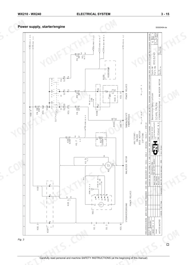
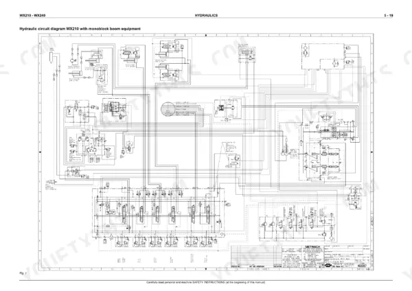
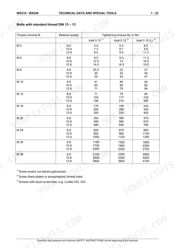
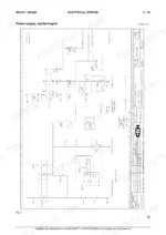
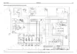
This 674-page Case WX210, WX240 Hydraulic Excavator Service Manual (OEM #9-91270) puts the complete PCS pump control system, CAN bus electronics, and drive unit rebuild procedures in your hands. Open it up and you get full electrical circuit diagrams down to individual connector pin assignments (X33A through X33P), hydraulic schematics covering every cylinder circuit from boom regeneration to slewing and grab rotation, and a fault code section for both the PCS unit and central unit. It's grounded in real numbers too: the coolant temperature sensor torques to 20-30 Nm on a ½-inch x 14 PTF thread, and the B10.1 speed sensor coil should read 450 Ω ± 20 Ω at 20°C. No more chasing an intermittent CAN fault with a test light and hope. Bookmarked by section so you jump straight from wiring to hydraulics to repair instructions, then pull it up on your tablet and get back under the machine.
What's Inside This Case WX210, WX240 Manual
| System | Pages | Key Topics |
|---|---|---|
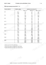
| Safety & Technical Data | 6-99 | Safety Instructions, Warnings and Symbols, Technical Characteristics, Si Units and Conversions, Special Tools, Service Data |
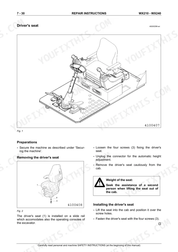
| Machine Construction | 96-148 | Superstructure Components Overview, Engine Assembly Layout, Boom-Adjusting Equipment, Machine Description |
| Electrical System & Circuit Diagrams | 144-231 | Electrical Control, Fuses, Full Electrical Circuit Diagrams, Part Numbers, Wiring |
| Electronic Control (Esx / CAN Bus) | 232-292 | Electronic Control Unit, CAN Bus Digital Technique, Esx Coding, Pcs Power Control System, Load-Limit Regulator, Speed and Coolant Sensors |
| Hydraulic System: Pumps & Control Block | 293-354 | Hydraulic Overview, Drive Unit, Multi-Circuit Variable Pump, Control Block front/rear Views, Pilot-Control System and Units |
| Travel, Brake & Steering Circuits | 355-390 | Travel Circuits 20/25/30 km/h with Schematics, Pressure Compensation, Braking, Steering and Fan Circuit |
| Work-Equipment Cylinder Circuits | 391-444 | Undercarriage and Stabilizer Circuits, Levelling Blade, Boom / Bucket / Stick / Adjusting Cylinder Circuits with Regeneration, Combined Functions |
| Attachment Circuits: Hammer, Shears & Crusher | 445-482 | Hydraulic Hammer Control Spool and Circuit, Hammer with Auxiliary Function, shears/crusher Control Spool and Electrical Circuit, Monoblock and Boom-Adjusting Boom Variants |
| Slewing System & Grab Rotation | 483-510 | Slewing Pump 4 Vg 71, Port Valve Plate, Slewing Gear, Grab Rotation Solenoid Valve and Schematic |
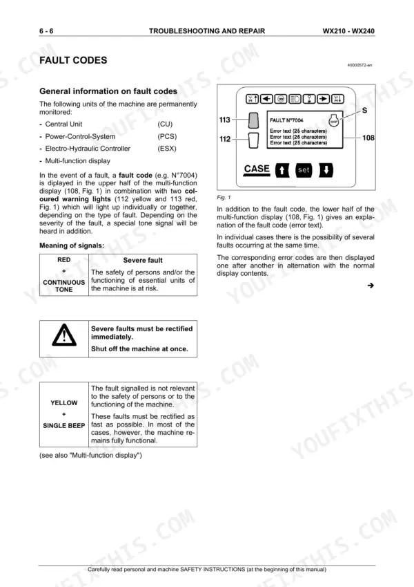
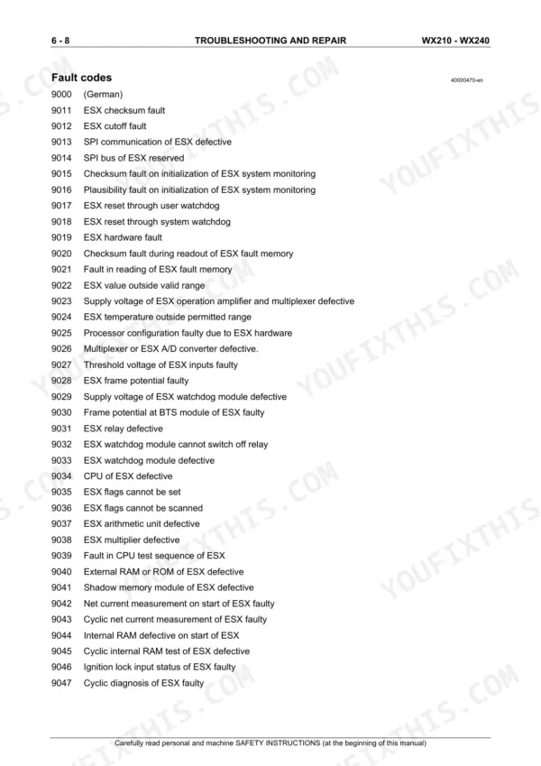
| Fault Codes & Troubleshooting | 506-536 | Fault Code Diagnosis, Pcs Unit and Central Unit Fault Codes, Troubleshooting Procedures |
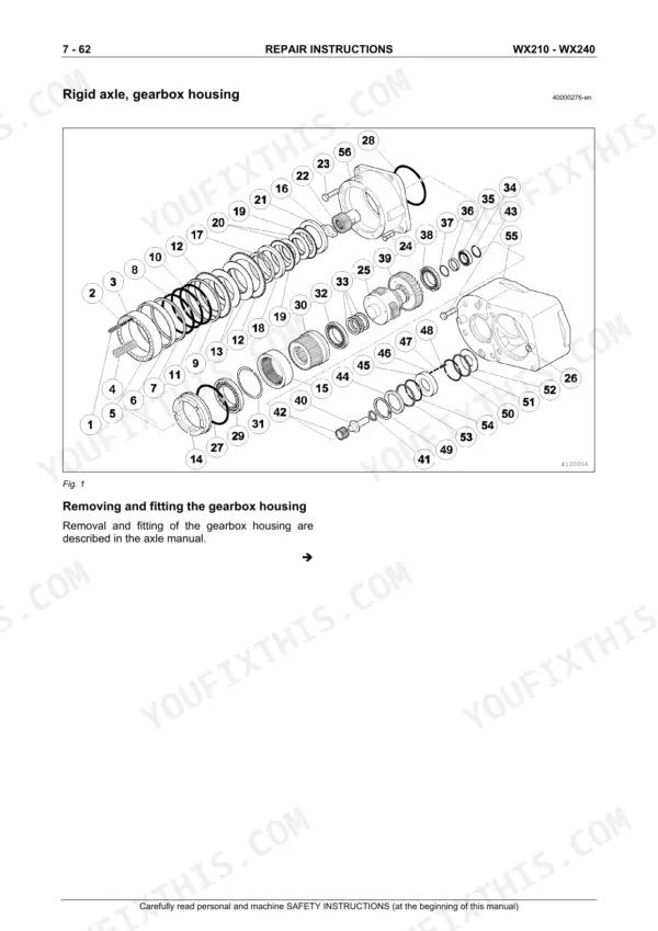
| Repair Instructions: Superstructure, Undercarriage & Cylinders | 537-665 | Welding Operations, Superstructure Component R&R, Slewing Gearbox and Ball-Bearing Slewing Ring, Axles and Gearboxes, Brake Disks, Boom Cylinders for Monoblock and Shift Booms |
| Wear Parts & Engine | 666-674 | Wear Limits, Slip-On Teeth, Trenching Grab, Lamp Bulbs, Diesel Engine, Combined Radiator, Coolant Expansion Tank, Air Filter |
Quick Reference Specifications
| Specification | Value | Page |
|---|---|---|
| Engine coolant temperature sensor tightening torque | 20 to 30 Nm | p. 272 |
| Engine coolant temperature sensor thread | ½“ x 14 PTF | p. 272 |
| Speed sensor B10.1 coil resistance at 20°C | 450 Ω +/- 20 Ω | p. 271 |
| Coolant temperature sensor B13.1 tightening torque | 20 to 30 Nm | p. 272 |
| Hydraulic oil temperature sensor R14 tightening torque | 20 Nm | p. 274 |
| Proportional valve Y10 PWM frequency | 150 Hz | p. 275 |
| Fan control valve Y131 tightening torque | 50 Nm | p. 277 |
| Tyre inflation pressure (10.00–20PR16) | 6.5 bar | p. 615 |
| Cardan shaft tightening torque | 60 Nm | p. 586 |
| Floating-axle cylinder screw plug tightening torque | 180 Nm | p. 612 |
Case WX210, WX240 Common Problems This Manual Covers
Case WX210 boom won't hold position, cylinder drifts down under a loaded bucket
Depressurize the hydraulic system per the procedure before cracking any lines open. Pull the boom cylinder per the Boom Cylinder Circuit section and check the piston seal and control valve spool for scoring. Bench test the spool for internal bypass; replace worn seals and reassemble to the section's fit tolerances before repressurizing.
Manual Section: Boom Cylinder Circuit p. 407Stick cylinder creeps in and won't stay put when the machine sits idle on a slope
Check the stick check valve and regeneration circuit for a leaking poppet before you tear down the cylinder. Depressurize the hydraulic system first, per the procedure covering brake and hydraulic depressurization. Pull the cylinder, inspect the rod seal and check valve seat for wear, and replace both together rather than one at a time.
Manual Section: Stick Cylinder Circuit with Regeneration Function p. 425Total loss of hydraulic drive power together with an engine derate warning on the display
Verify the pump drive coupler first, this is the most common cause of a sudden power loss paired with a derate. Check the Pcs performance regulating circuit for a stuck load-limit regulator, and confirm the speed sensor B10.1 coil resistance reads 450 ohms plus or minus 20 ohms at 20 degrees C on page 271. A reading outside that range points to sensor failure, not the pump itself.
Manual Section: Pcs Components p. 268Random shutdown with dash lights flickering and fault code 9151 on the display
Fault code 9151 flags a CAN bus communication error, don't chase electronics until you've ruled out wiring. Check the connector pin assignments at X33A through X33E for corrosion or a loose pin, then verify continuity across the harness runs to Central Unit A100. Reseat and dielectric-grease every connector you disturb before clearing the code and re-testing.
Manual Section: Fault Codes p. 513Hydraulic oil runs hot and boom response goes sluggish once the machine's been working an hour
Check the hydraulic oil temperature sensor R14 first; it's torqued to 20 Nm on page 274 and a loose or failed unit gives false high readings before the oil actually overheats. If the reading is genuine, pull the cooler core and flush it, debris packed between the fins is the usual culprit on machines running in dusty conditions. Confirm coolant flow afterward before returning the machine to work.
Manual Section: Pcs Components p. 274Multi-function display throws a Pcs unit fault with erratic gauge readings across the panel
Start at the Pcs unit fault code listing and match the exact code shown on the display before swapping parts. Check the Central Unit connector pins and confirm the coolant temperature sensor B13.1 is torqued correctly to 20 to 30 Nm on page 272, a loose sensor is a common trigger for erratic gauge behavior. Clear the fault and cycle the key to confirm it doesn't return.
Manual Section: Fault Codes p. 511Frequently Asked Questions
How to reset the error code on Case WX210/WX240 wheeled excavator?
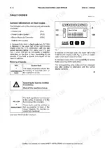
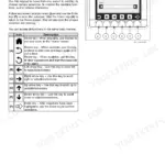
Fault codes can be reset (erased) using the "fault reset (erasing)" function, which is part of the "Service" menu (item 108j) in the Multifunction display. This function is reserved for the Service Department and is not accessible during normal machine operation. p. 134
How to reset the hydraulic system after a fault on Case WX210/WX240?
To reset the hydraulic system after a fault, first depressurize it by standing the working equipment on the ground, shutting off the engine, turning the electrical system key-switch to ON, switching on pilot control (lever 72), and moving control levers/pedals in all directions. After repairs, lubricate all points, check oil levels, and perform a functional test of all repaired components and functions before returning the excavator to service. p. 548
Where is the reset button for diagnostic codes on Case WX210/WX240?
The manual does not describe a physical "reset button" for diagnostic codes. Fault codes can be reset (erased) via the "Service" function (item 108j) in the Multifunction display, which is reserved for the Service Department. The central electronic unit (A100) and multi-function display (C4) can also be programmed/flash-loaded via the diagnosis socket A10X4 using a service tool. p. 134
How to reset engine warning light on Case WX210/WX240?
The manual indicates that engine warning lights (yellow or red) illuminate when a fault occurs. To clear the warning light, the underlying cause of the fault must be rectified. The yellow warning light (item 112) will be displayed after the cause of a red fault (item 113) is removed. p. 138
How is this Case WX210 Service Manual delivered?
Immediate download of the complete 674-page searchable Service Manual. Access it on any device, from a laptop at your desk to a phone in the field.
Can I print this Case WX210 manual?
No restrictions at all. Print individual pages, full chapters, or the entire manual. The PDF is completely unlocked.
Does this Case WX210 manual show the hydraulic circuits?
Full hydraulic system diagrams are included, covering circuits, valve locations, and hydraulic component specs for the Case WX210, WX240.







Reviews
There are no reviews yet.